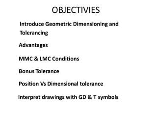
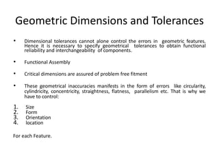
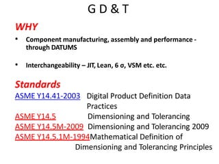
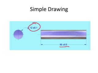
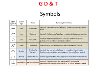
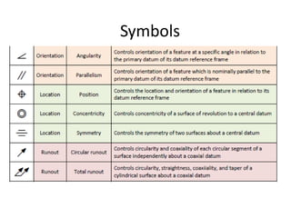
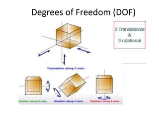
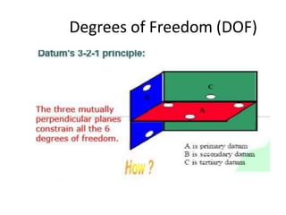
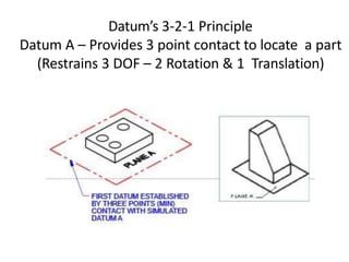
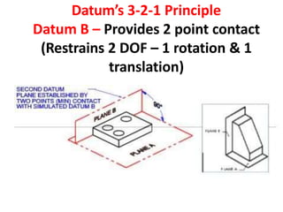
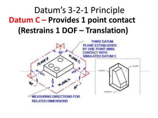
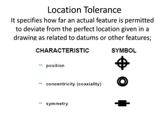
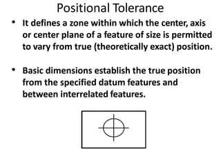
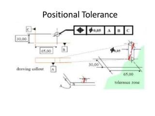
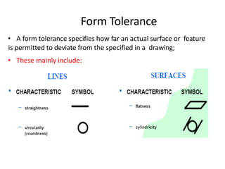
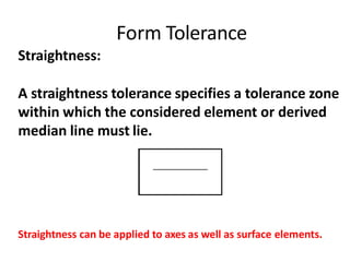
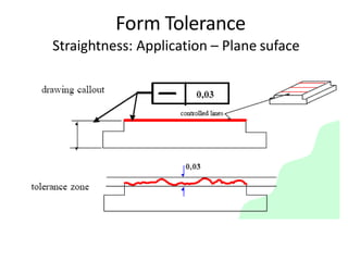
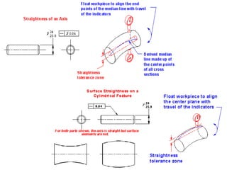
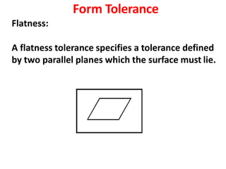
This document provides an overview of geometric dimensioning and tolerancing (GD&T). It defines GD&T, discusses its objectives and advantages over conventional tolerancing methods. It describes the different GD&T concepts like datums, degrees of freedom, positional tolerancing and bonus tolerance. It also explains various geometric tolerances like straightness, flatness, circularity and their applications. Finally, it emphasizes that GD&T is important for designers, manufacturers and inspectors to ensure a common interpretation of drawings and maintain the design intent.
GD&T is an international way of describing a part accurately. It is used widely in all manufacturing sectors for part dimensioning. This ppt contains basic overview of GD&T. The detailed version will be uploaded soon.
Geometric dimensioning and tolerancing is the new way of describing the dimensions and tolerances. It developed by engineers and used by engineers in engineering drawings or drafting. It plays a very important role in engineering design.
This presentation contains all the basic information about GD&T.
A basic 2 day training on understanding of GDnT,Geometrical Dimensioning & Tolerancing to Technical & Egineering Group as a common language in understanding Drawings.
Trainer & Speaker
Timothy Wooi,
20C,Taman Bahagia,06000,Jitra, Kedah. Malaysia
email: timothywooi2@gmail.com
GD&T is a means of dimensioning & tolerancing a drawing which considers the function of the part and how this part functions with related parts.
GD&T has increased in practice in last 15 years because of ISO 9000.
ISO 9000 requires not only that something be required, but how it is to be controlled. For example, how round does a round feature have to be?
GD&T is a system that uses standard symbols to indicate tolerances that are based on the feature’s geometry.
Sometimes called feature based dimensioning & tolerancing or true position dimensioning & tolerancing
GD&T practices are specified in ANSI Y14.5M-1994.
GD&T for Omega Fabrication, Melaka.4-5th March 2017Timothy Wooi
GD&T Course Objective
Provide Participants with Fundamental concepts of GD&T to express, understand and interpret drawing requirements using GD&T to ASME Y14.5 Standards.
To allow Participants to master techniques of GD&T in the ASME standard to;
integrate smoothly into engineering design applications and modern inspection systems at work.
This ppt describes Profile & Runout CONTROLS in GD&T. It also showcase the differences & similarities between the two controls. Kindly suggest your comments as required. Thank you + Regards.
This PPT discuss the 14 geometric symbols used in GD&T classified under five controls. Only important points are mentioned. Kindly mention, if any other important points are missed out. The sources of the content (including pics) are from various sites which details GD&T. The PPT with modifiers and additional symbols (in detail) will be updated soon.
GD&T stands for Geometric Dimensioning and Tolerancing, as defined by ASME Y14.5.Geometric tolerancing, is an exact language that enables designers to “say what they mean” on a drawing, thus improving product designs.
Production uses the language to interpret the design intent, and Inspection looks to the language to determine set up.
GD&T is a method for stating and interpreting mechanical engineering design requirements. GD&T is a very useful & efficient tool to make engineering drawings a better means of communication from design through manufacturing and inspection.
GD&T: An International Language & and an Exact Language that provides Uniformity.
Student information management system project report ii.pdfKamal Acharya
Our project explains about the student management. This project mainly explains the various actions related to student details. This project shows some ease in adding, editing and deleting the student details. It also provides a less time consuming process for viewing, adding, editing and deleting the marks of the students.
Water scarcity is the lack of fresh water resources to meet the standard water demand. There are two type of water scarcity. One is physical. The other is economic water scarcity.
Hierarchical Digital Twin of a Naval Power SystemKerry Sado
A hierarchical digital twin of a Naval DC power system has been developed and experimentally verified. Similar to other state-of-the-art digital twins, this technology creates a digital replica of the physical system executed in real-time or faster, which can modify hardware controls. However, its advantage stems from distributing computational efforts by utilizing a hierarchical structure composed of lower-level digital twin blocks and a higher-level system digital twin. Each digital twin block is associated with a physical subsystem of the hardware and communicates with a singular system digital twin, which creates a system-level response. By extracting information from each level of the hierarchy, power system controls of the hardware were reconfigured autonomously. This hierarchical digital twin development offers several advantages over other digital twins, particularly in the field of naval power systems. The hierarchical structure allows for greater computational efficiency and scalability while the ability to autonomously reconfigure hardware controls offers increased flexibility and responsiveness. The hierarchical decomposition and models utilized were well aligned with the physical twin, as indicated by the maximum deviations between the developed digital twin hierarchy and the hardware.
Cosmetic shop management system project report.pdfKamal Acharya
Buying new cosmetic products is difficult. It can even be scary for those who have sensitive skin and are prone to skin trouble. The information needed to alleviate this problem is on the back of each product, but it's thought to interpret those ingredient lists unless you have a background in chemistry.
Instead of buying and hoping for the best, we can use data science to help us predict which products may be good fits for us. It includes various function programs to do the above mentioned tasks.
Data file handling has been effectively used in the program.
The automated cosmetic shop management system should deal with the automation of general workflow and administration process of the shop. The main processes of the system focus on customer's request where the system is able to search the most appropriate products and deliver it to the customers. It should help the employees to quickly identify the list of cosmetic product that have reached the minimum quantity and also keep a track of expired date for each cosmetic product. It should help the employees to find the rack number in which the product is placed.It is also Faster and more efficient way.
Overview of the fundamental roles in Hydropower generation and the components involved in wider Electrical Engineering.
This paper presents the design and construction of hydroelectric dams from the hydrologist’s survey of the valley before construction, all aspects and involved disciplines, fluid dynamics, structural engineering, generation and mains frequency regulation to the very transmission of power through the network in the United Kingdom.
Author: Robbie Edward Sayers
Collaborators and co editors: Charlie Sims and Connor Healey.
(C) 2024 Robbie E. Sayers
CFD Simulation of By-pass Flow in a HRSG module by R&R Consult.pptxR&R Consult
CFD analysis is incredibly effective at solving mysteries and improving the performance of complex systems!
Here's a great example: At a large natural gas-fired power plant, where they use waste heat to generate steam and energy, they were puzzled that their boiler wasn't producing as much steam as expected.
R&R and Tetra Engineering Group Inc. were asked to solve the issue with reduced steam production.
An inspection had shown that a significant amount of hot flue gas was bypassing the boiler tubes, where the heat was supposed to be transferred.
R&R Consult conducted a CFD analysis, which revealed that 6.3% of the flue gas was bypassing the boiler tubes without transferring heat. The analysis also showed that the flue gas was instead being directed along the sides of the boiler and between the modules that were supposed to capture the heat. This was the cause of the reduced performance.
Based on our results, Tetra Engineering installed covering plates to reduce the bypass flow. This improved the boiler's performance and increased electricity production.
It is always satisfying when we can help solve complex challenges like this. Do your systems also need a check-up or optimization? Give us a call!
Work done in cooperation with James Malloy and David Moelling from Tetra Engineering.
More examples of our work https://www.r-r-consult.dk/en/cases-en/
8. Geometric Dimensioning & Tolerancing
DEFINITION
GD & T is a means of dimensioning and Tolerancing a
drawing by considering the function of the part and
how this part functions with related parts.
9. OBJECTIVIES
Introduce Geometric Dimensioning and
Tolerancing
MMC & LMC Conditions
Bonus Tolerance
Position Vs Dimensional tolerance
Advantages
Interpret drawings with GD & T symbols
10. Geometric Dimensions and Tolerances
• Dimensional tolerances cannot alone control the errors in geometric features.
Hence it is necessary to specify geometrical tolerances to obtain functional
reliability and interchangeability of components.
• Functional Assembly
• Critical dimensions are assured of problem free fitment
• These geometrical inaccuracies manifests in the form of errors like circularity,
cylindricity, concentricity, straightness, flatness, parallelism etc. That is why we
have to control:
1. Size
2. Form
3. Orientation
4. location
For each Feature.
11. Who need GD&T
It is a industrial requirement which is equally
important for :
• Designer
• Manufacturers
• Inspectors
Common interpretation of drawings among these
people is critical to preserve design intent.
12. Advantages
Engineers, Designers, Quality Inspector and manufacturer should have
knowledge on GD&T. It is really important in drawing interpretation
based on application knowledge. GD&T knowledge will reduce product
design time & production cost. Some of the advantages of GD&T are
listed below.
1. Standardization of parts.
2. Product can be made in any country.
3. Only one interpretation of drawing.
4. International language for drawings
5. Manufacturing and metrology is distinctly specified.
6. More tolerance with more control then conventional method of
tolerance.
7. Neat drawings with less notes and revisions.
13. G D & T
WHY
• Component manufacturing, assembly and performance -
through DATUMS
• Interchangeability – JIT, Lean, 6 σ, VSM etc. etc.
Standards
ASME Y14.41-2003
ASME Y14.5
Digital Product Definition Data
Practices
Dimensioning and Tolerancing
ASME Y14.5M-2009 Dimensioning and Tolerancing 2009
ASME Y14.5.1M-1994Mathematical Definition of
Dimensioning and Tolerancing Principles
16. Mil-std 1949
Established Rule #1
Unless otherwise specified, the limits of size of
an individual feature of size control the form of
the feature as well as the size.
Then Asme standards started in 1966 with
revision time to time like in 1982, 1994 and
2009. Asme Y14.5 2009 is current standard
which will be upgraded in 2017 .
21. How to read GD & T ?
- Location, Form, Profile, Run out or an
Orientation Tolerance
- Value of tolerance
- Bonus tolerance
- Size of feature – MMC to LMC
- Datum s
22. GD & T Groups
Tolerances grouped to
• Form : Controls the shape of the given feature
• Orientation : Controls both Orientation and Form
• Location : Controls position, orientation & Form
• Run Out : Control position, Orientation & Form
23. Hierarchy of GD & T
Location
Orientation
Form
• Location is the most general form of control. It controls
both orientation and form
• Orientation is a refinement of location. It is used when
position controls is insufficient
• Form is a refinement of orientation. It is used when
orientation control is insufficient
• Form Tol < Orientation tol < Location tol
24. Form Deviation
Form deviation is the deviation of a feature from its
nominal (Defined) form (Shape). The feature being
controlled may be a line on a surface, a surface or a
geometric element, e.g., an axis. Form deviations are
specified without reference to any other features.
25. Orientation Deviation
• An orientation deviation is a deviation from
nominal form AND orientation.
• An orientation deviation must be related to one or more
features, which are referred to as datums.
• The datums must be defined first before an orientation
tolerance can be specified.
26. Position Deviation
• Position deviation is controlled relative to a datum.
• A nominal position (distance & direction) is given relative to a
datum.
• The position tolerance defines the max permissible deviation
from this nominal position.
• The deviation is shown in green.
27. MMC
The condition in which a feature of size contains the max
amount of material with in the stated limits of size
For Holes : Min hole diameter
For Shafts : Max shaft diameter
MMC is the condition where the most part material is present at the surface,or
where the part weighs the most.
29. LMC
The condition in which a feature of size contains the least
amount of material or the min amount of material with in
the stated limits of size.
For Holes : Max hole diameter
For Shafts : Min shaft diameter
LMC is the condition where the least part material is present at the surface, or
where the part weighs the least.
31. RFS – Regardless of Feature
• RFS applies, with respect to the individual
tolerance, datum reference, or both, where no
modifying symbol is specified.
• MMC or LMC must be specified on the drawing
where it is required (i.e)
– RFS is the default, if no modifier is given
– The tolerance zone is not affected by the actual size of the
feature
32. Datum / Datum feature
Datum : A theoretical exact point, axis or plane
used as the origin from which the location or
geometric characteristics of a feature of a part
are established.
Datum features : An actual feature of a part
used to establish a datum.
36. Bonus Tolerance
• It is an additional tolerance, added to the given
geometrical tolerance, based on the actual size of the
given feature.
• As the feature size departs from MMC, an increase in
the geometrical tolerance is permitted equal to the
departure. This departure is called as “BONUS”
tolerance.
• Bonus tolerance is applicable only when MMC or LMC
is indicated in the feature control frame.
44. Location Tolerance
It specifies how far an actual feature is permitted
to deviate from the perfect location given in a
drawing as related to datums or other features;
45. Positional Tolerance
• It defines a zone within which the center, axis
or center plane of a feature of size is permitted
to vary from true (theoretically exact) position.
• Basic dimensions establish the true position
from the specified datum features and
between interrelated features.
50. Form Tolerance
• A form tolerance specifies how far an actual surface or feature
is permitted to deviate from the specified in a drawing;
• These mainly include:
51. Form Tolerance
Straightness:
A straightness tolerance specifies a tolerance zone
within which the considered element or derived
median line must lie.
Straightness can be applied to axes as well as surface elements.