Downloaded 808 times
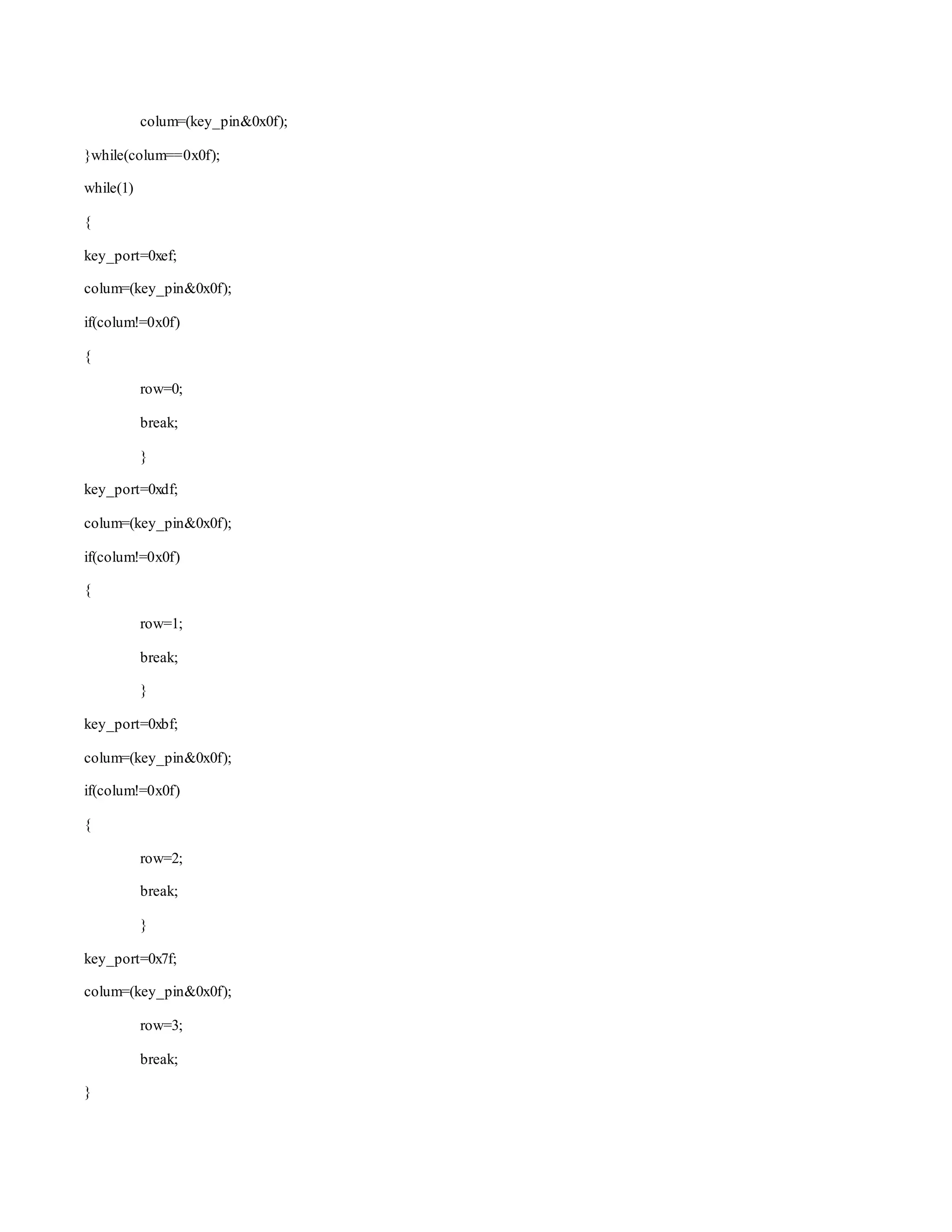
![Function to identify a key pressed
//connect colum with lower nibble and rows with upper nibble
#define key_port PORTA
#define key_ddr DDRA
#define key_pin PINA
unsigned char keypad[4][4]={'7','8','9','/',
'4','5','6','*',
'1','2','3','-',
'c','0','=','+'};
char takekey()
{
unsigned char row,colum;
char key;
key_ddr=0xf0;
key_port=0xff;
do
{
key_port&=0x0f;
colum=(key_pin&0x0f);
}while(colum!=0x0f);
do
{
do
{
_delay_ms(1);
key_port&=0x0f;
colum=(key_pin&0x0f);
}while(colum==0x0f);
_delay_ms(1);
key_port&=0x0f;](https://image.slidesharecdn.com/passwordbaseddoorlocksystem-141209062658-conversion-gate01/75/Password-based-door-locksystem-5-2048.jpg)
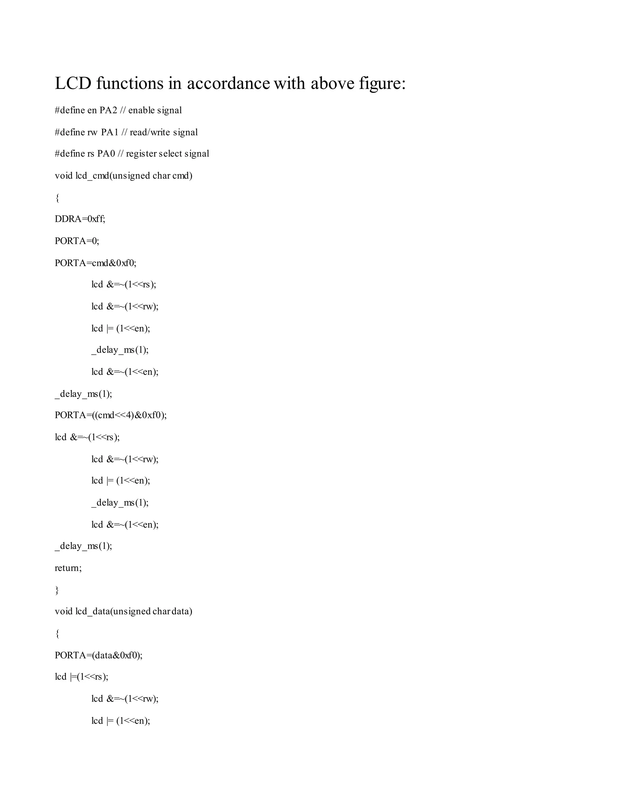
![if(colum==0x0e)
key=keypad[row][0];
else if(colum==0x0d)
key=keypad[row][1];
else if(colum==0x0b)
key=keypad[row][2];
else
key=keypad[row][3];
return(key);
}
Interfacing 2x16 LCD with microcontroller (in 4 bit mode)
LCD interfacing with atmega 16](https://image.slidesharecdn.com/passwordbaseddoorlocksystem-141209062658-conversion-gate01/75/Password-based-door-locksystem-7-2048.jpg)
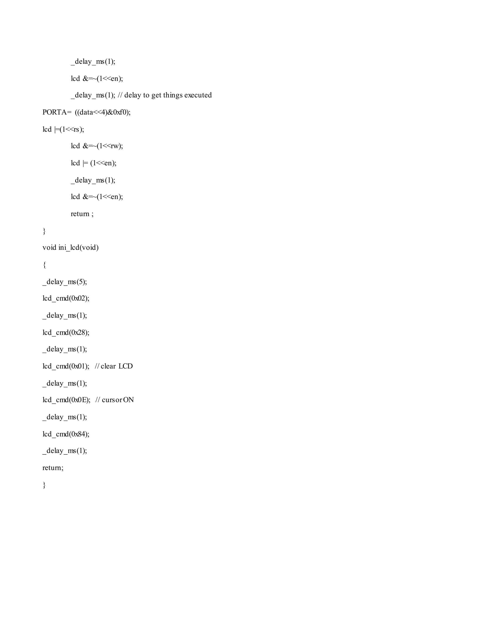
![Description:
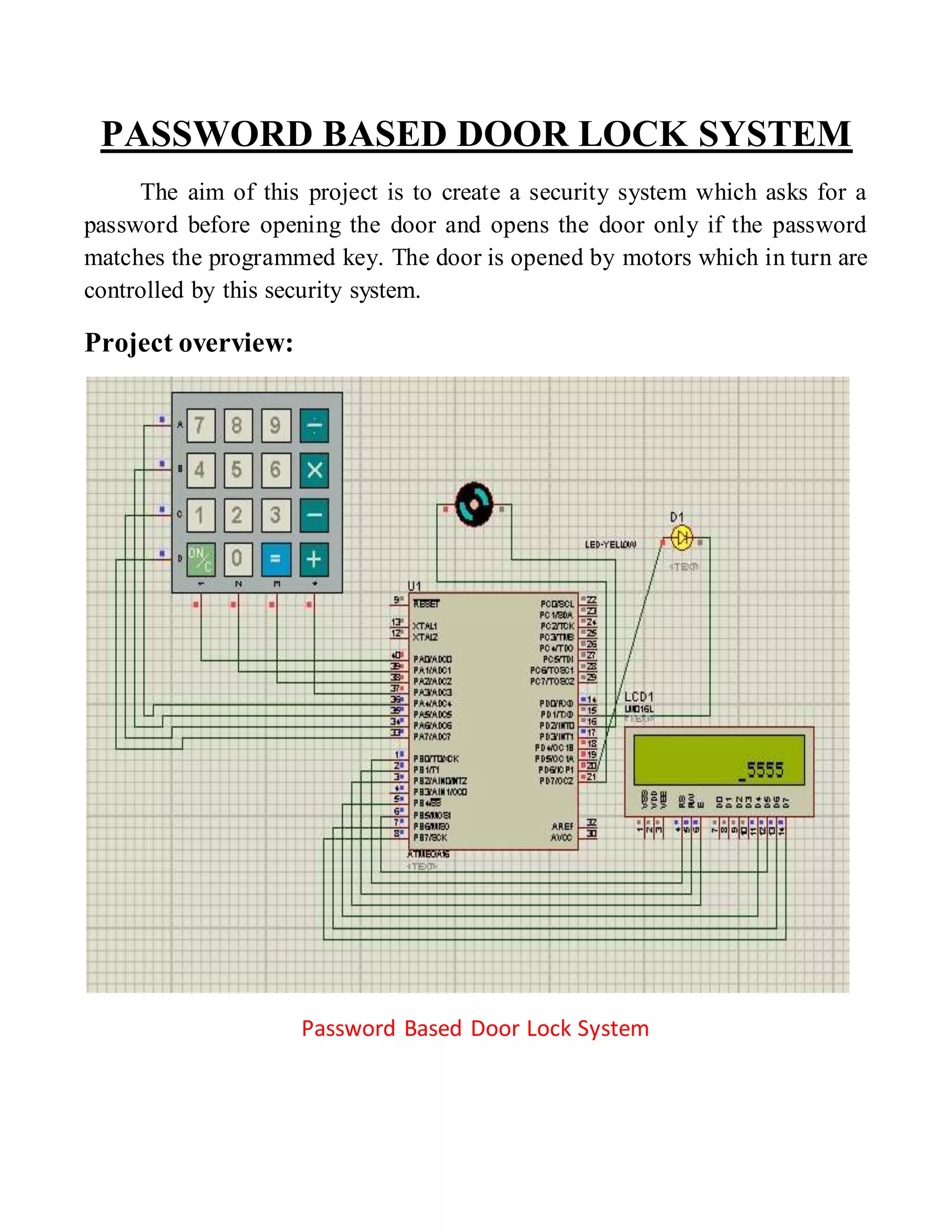
This system works as follows to open the door:-
i. Asks for the visitor to enter the Password.
ii. If entered password matches the programmed one then it glows the
indicator and run the motors to open the door otherwise takes the
programmed action.
Main Program:
#include<avr/io.h>
#include<util/delay.h>
#include"keypad.h"
#include"4bitlcd.h"
void main()
{
unsigned int pass=5555,key,key1,ch1;
unsigned char ch=0,i,w[]="wrong password",E[]="ENTER PASSWORD";
DDRD=0XFF;
DDRB=0XFF;
_delay_ms(500);
ini_lcd();
while (1)
{
key=0;](https://image.slidesharecdn.com/passwordbaseddoorlocksystem-141209062658-conversion-gate01/75/Password-based-door-locksystem-10-2048.jpg)
![ch=0;
lcd_cmd(0X80);
for(i=0;i<15; i++)
lcd_data(E[i]);
lcd_cmd(0xC0);
while(ch!='=') //get password from visitor
{
ch=takekey();
ch1=ch;
if(ch!='=')
{
lcd_data(ch);
key=((key*10)+(ch1-0x30));
}
else
break;
}
lcd_cmd(0x01);
lcd_cmd(0xce);
key1=key;
while(key)
{
lcd_data((key%10)+0x30);
lcd_cmd(0x10);](https://image.slidesharecdn.com/passwordbaseddoorlocksystem-141209062658-conversion-gate01/75/Password-based-door-locksystem-11-2048.jpg)
![lcd_cmd(0x10);
key=key/10;
}
ch=takekey();
if(key1!=5555) //compare the entered password
{
lcd_cmd(0x01);
lcd_cmd(0xc1);
for(i=0;i<15; i++)
lcd_data(w[i]);
PORTD=0X0f;
ch=takekey();
}
else
{
PORTD=0XF0;
ch=takekey();
PORTD=0;
}
lcd_cmd(0x01);
}
}](https://image.slidesharecdn.com/passwordbaseddoorlocksystem-141209062658-conversion-gate01/75/Password-based-door-locksystem-12-2048.jpg)

This system creates a password protected door lock using a microcontroller. It takes a password input from the user via a keypad, compares it to the programmed password, and only opens the door motor if they match by setting a port. Otherwise, it displays a "wrong password" message on an LCD screen.