8051
•Download as DOCX, PDF•
0 likes•176 views

This document describes a project to detect which key is pressed on a 16-key keypad connected to an Atmel 89C51 microcontroller and display the corresponding key number on an output port. The keypad uses a 4x4 matrix with each row connected to input pins on one port and each column connected to the same port via pull-up resistors. The microcontroller scans the rows to detect which key is pressed based on the column output. Assembly code is written, simulated, loaded onto the microcontroller and tested to read the keypad and display results.

Recommended
More Related Content
What's hot
Similar to 8051
Similar to 8051 (20)
8051
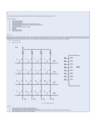
- 1. Aim To detect which key is pressed on a 16-key keypad (interfaced with Port1) and display the corresponding key number on Port0. Components/Software 1. Atmel 89C51 microcontroller 2. 8051 simulator- Win8051 3. Universal SP3 Programmer 4. Compiler and Software to load the code into Universal SP3 Programmer 5. Computer System with Windows 98 or later operating system and RS-232 Cable 6. +5V D.C Power Supply 7. 16-key keypad with keys arranged in 4x4 array 8. Resistors 9. Capacitors 10. 10 MHz crystal oscillator 11. Signal Generator and CRO Description Keypad is an array of 4x4 keys with each key being a switch. The four rows are connected to pins 0-3 of Port1 and the four columns to pins 4-7 of Port1 as shown in the figure below. Each column is also connected to supply voltage through a pull up resistor (around 1k Ohms). To read a particular key, the corresponding row is driven to '0'. In a key is pressed and the corresponding row is driven '0' then current flows through the corresponding pull up resistor and the corresponding column reads '0'. Otherwise the corresponding column reads '1' (open circuit). For example if Key 5 is pressed - R1 = 0, C1:C4 = 1111 R2 = 0, C1:C4 = 1011 Fig 42.1 Keypad schematic Procedure 1. Write the assembly code in Win8051. Compile and simulate it. 2. Once the code is error free, run it and check output with the Simulator 3. After checking the code in the simulator, the code (file with .HEX extension) is loaded into Atmel 89C51 microcontroller using Universal SP3 Programmer. 4. Now connections are made as shown in the circuit diagram.
- 2. 5. Switch on the supply and push Reset button 6. Observe the results 7. Switch off the supply Assembly Code