Downloaded 382 times


![The software for this project
#include <Keypad.h> void loop()
#include <EEPROM.h> {
char* secretCode = "1234"; char key = keypad.getKey();
int position = 0; if (key == '*' && ! Locked)
boolean locked = true; {
const byte rows = 4; // unlocked and * pressed so change code
const byte cols = 3; position = 0;
char keys[rows][cols] = getNewCode();
{{'1','2','3'},{'4','5','6'},{'7','8','9'},{'*','0','#'}}; updateOutputs();
byte rowPins[rows] = {2, 7, 6, 4}; }
byte colPins[cols] = {3, 1, 5}; if (key == '#‘){
Keypad keypad = Keypad(makeKeymap(keys), rowPins, locked = true;
colPins, rows, cols); position = 0;
int redPin = 9; updateOutputs(); }
int greenPin = 8; if (key == secretCode[position]){position ++;}
int solenoidPin = 10; if (position == 4)
void setup() { {
pinMode(redPin, OUTPUT); locked = false;
pinMode(greenPin, OUTPUT); updateOutputs();
loadCode(); }
flash(); delay(100);
updateOutputs(); } }](https://image.slidesharecdn.com/magneticdoorlockusingarduino-130217002653-phpapp01/75/Magnetic-door-lock-using-arduino-25-2048.jpg)
![void updateOutputs() void loadCode()
{ {
if (locked){ if (EEPROM.read(0) == 1){
digitalWrite(redPin, HIGH); secretCode[0] = EEPROM.read(1);
digitalWrite(greenPin, LOW); secretCode[1] = EEPROM.read(2);
digitalWrite(solenoidPin, HIGH);} secretCode[2] = EEPROM.read(3);
else{ secretCode[3] = EEPROM.read(4);}
digitalWrite(redPin, LOW); }
digitalWrite(greenPin, HIGH); void saveCode()
digitalWrite(solenoidPin, LOW);} {
} EEPROM.write(1, secretCode[0]);
EEPROM.write(2, secretCode[1]);
void getNewCode(){ EEPROM.write(3, secretCode[2]);
flash(); EEPROM.write(4, secretCode[3]);
for (int i = 0; i < 4; i++ ) EEPROM.write(0, 1);
{ }
char key; void flash()
key = keypad.getKey(); {
while (key == 0){key = keypad.getKey();} digitalWrite(redPin, HIGH);
flash(); digitalWrite(greenPin, HIGH);
secretCode[i] = key; delay(500);
} digitalWrite(redPin, LOW);
saveCode();flash();flash(); digitalWrite(greenPin, LOW);
} }](https://image.slidesharecdn.com/magneticdoorlockusingarduino-130217002653-phpapp01/75/Magnetic-door-lock-using-arduino-26-2048.jpg)
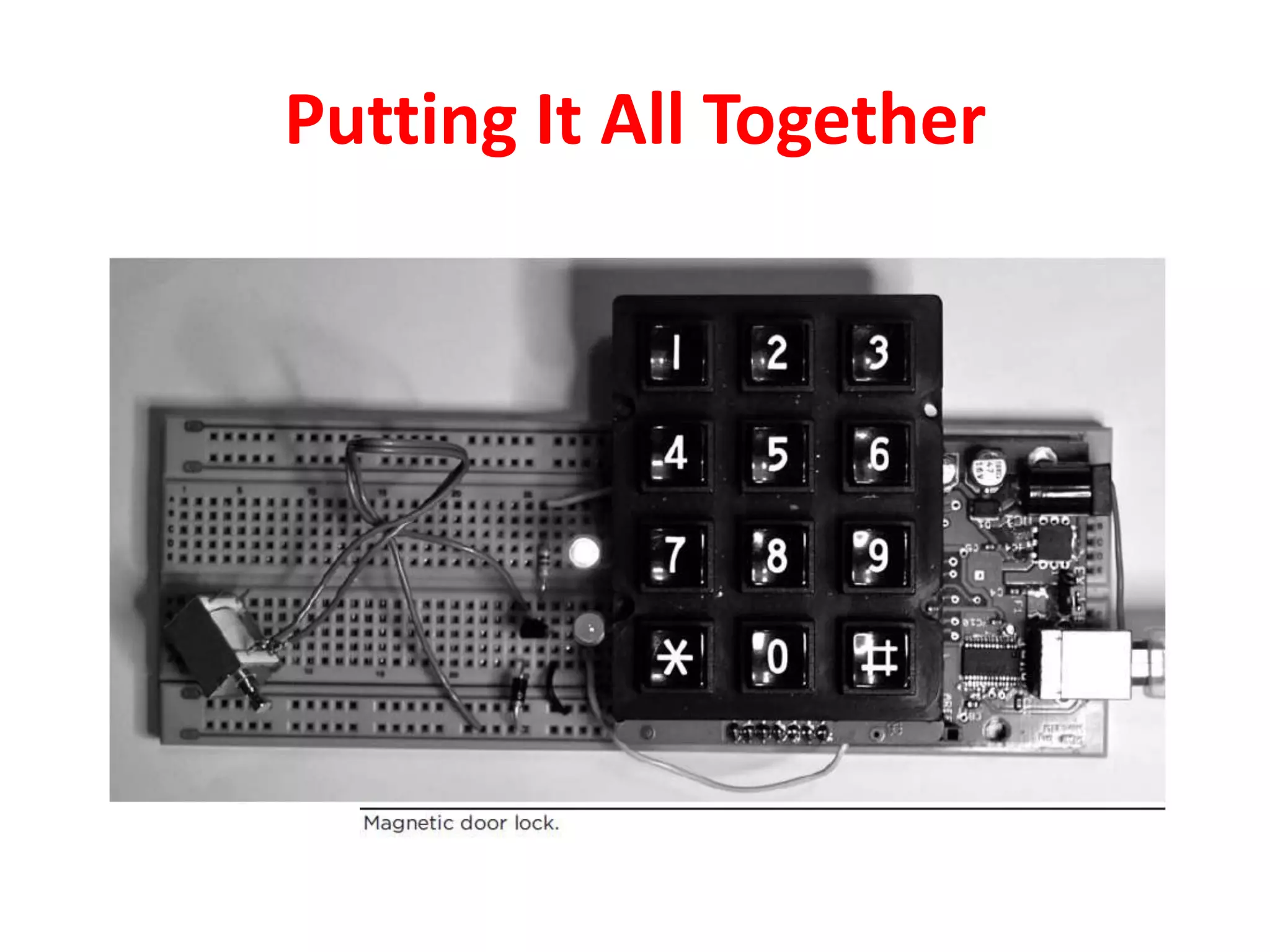


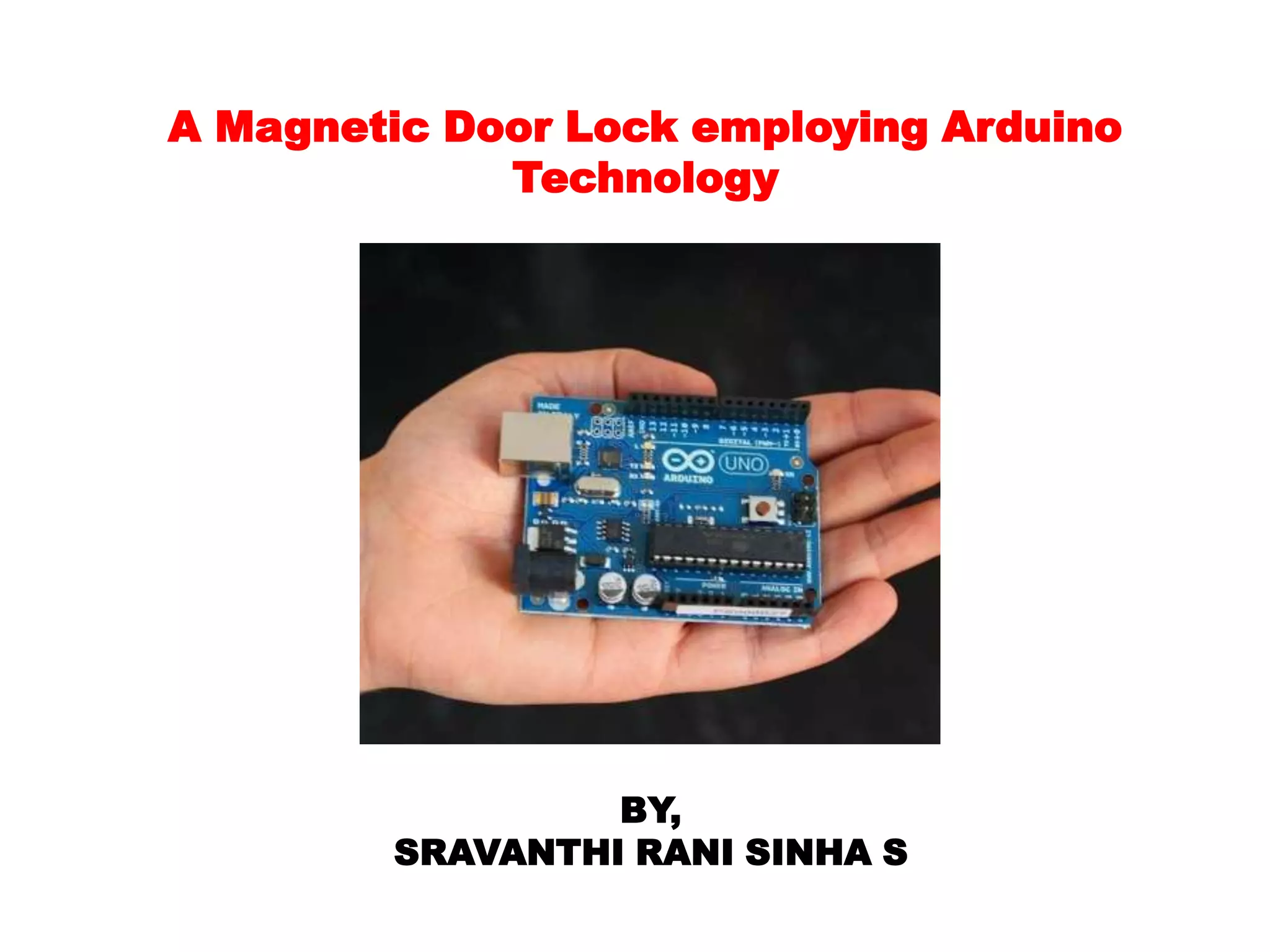
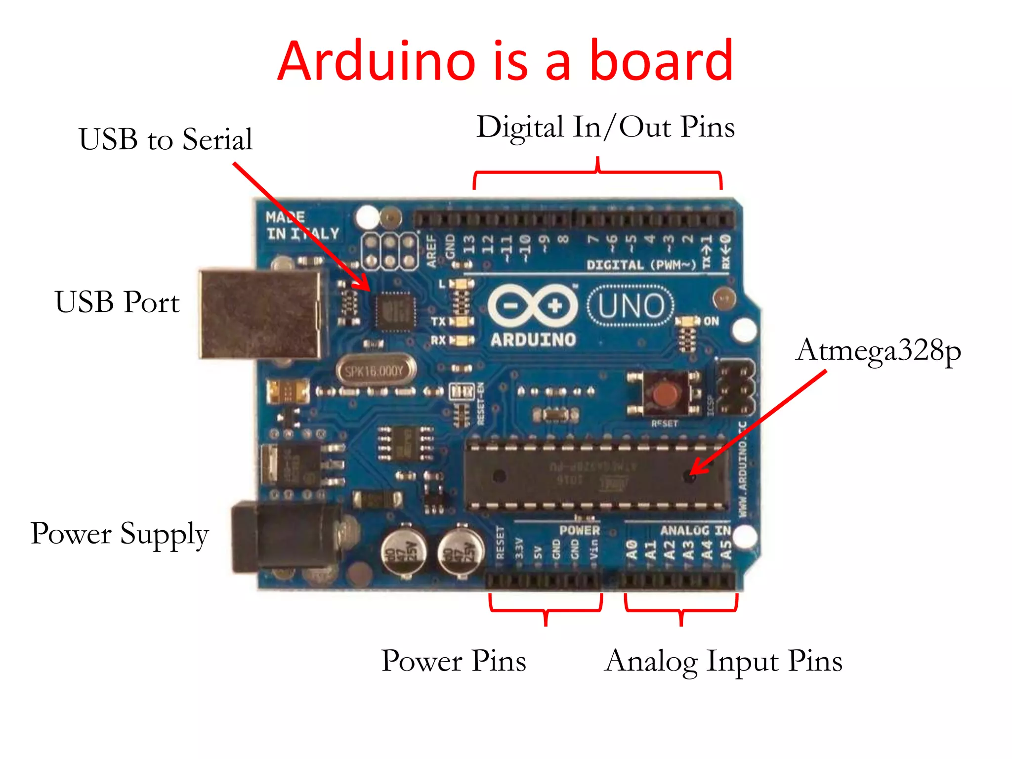
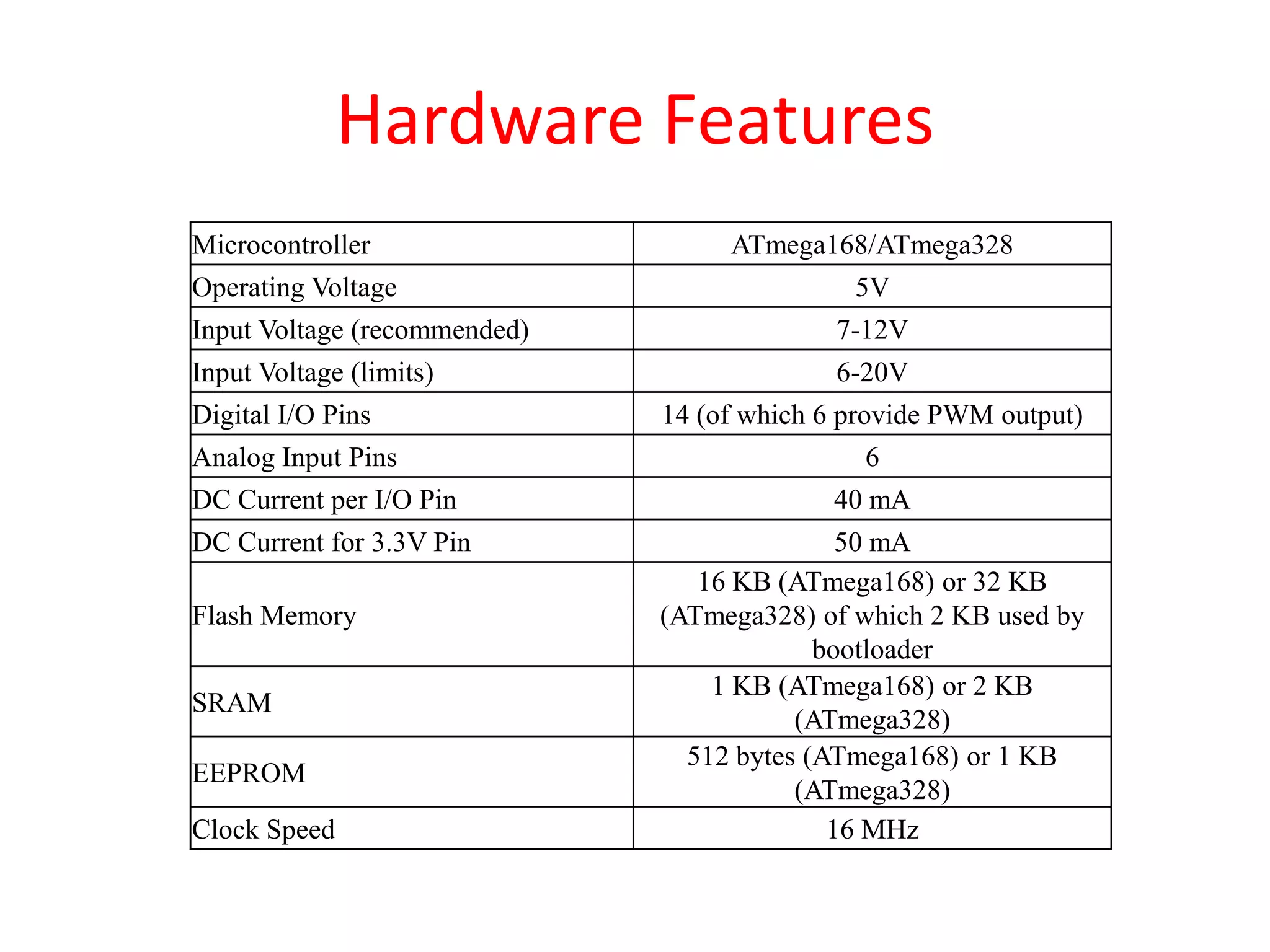
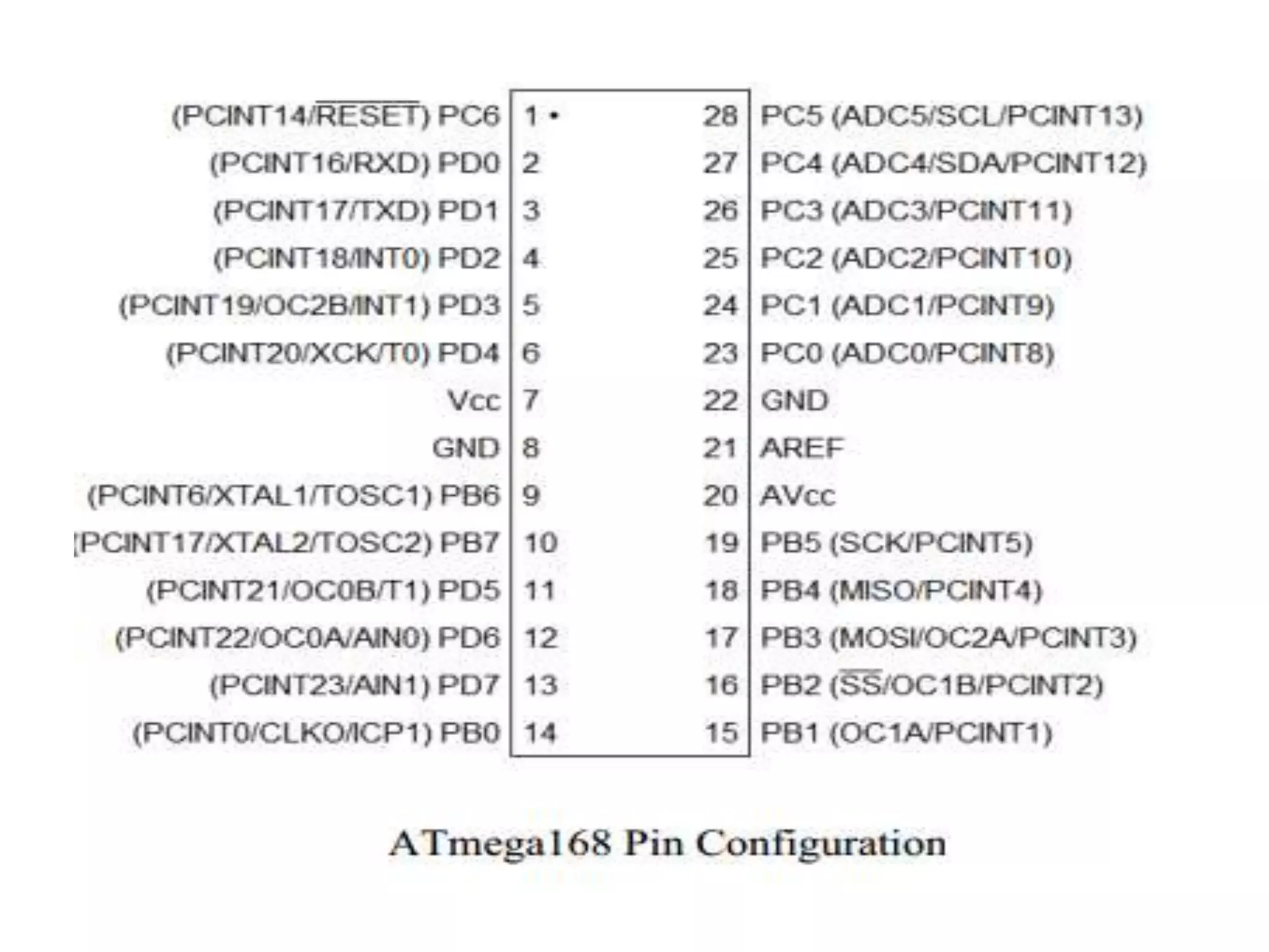
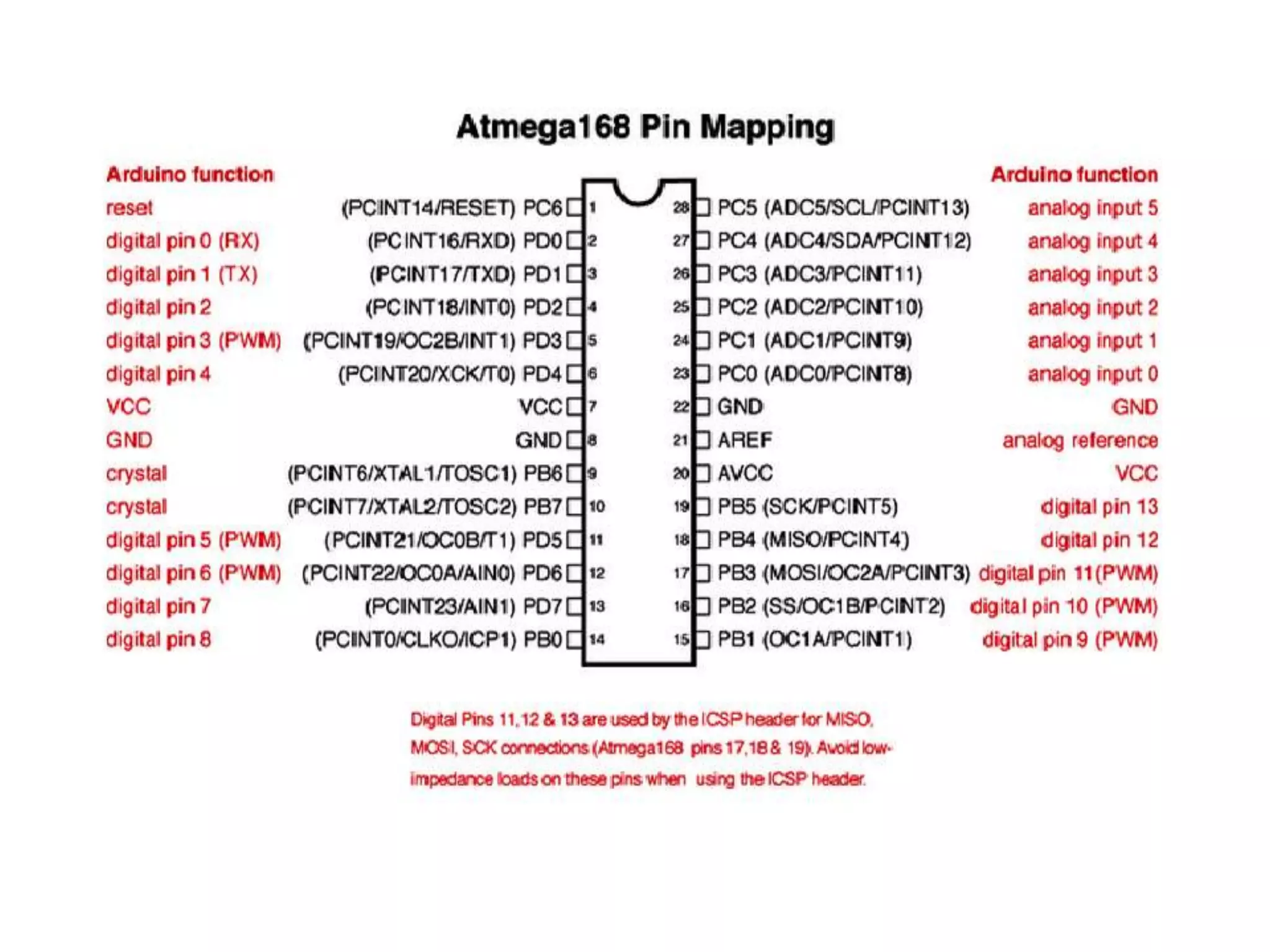
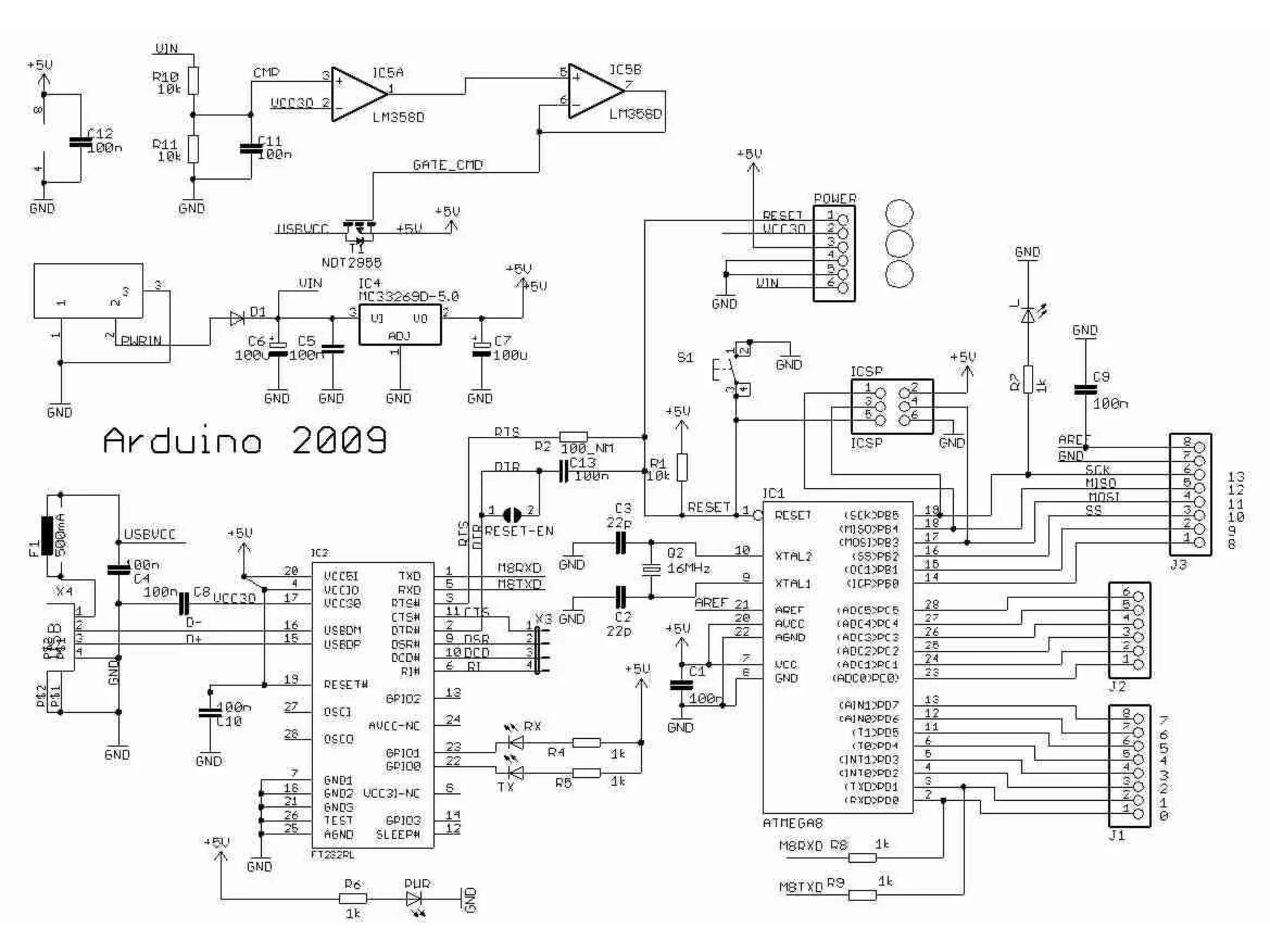
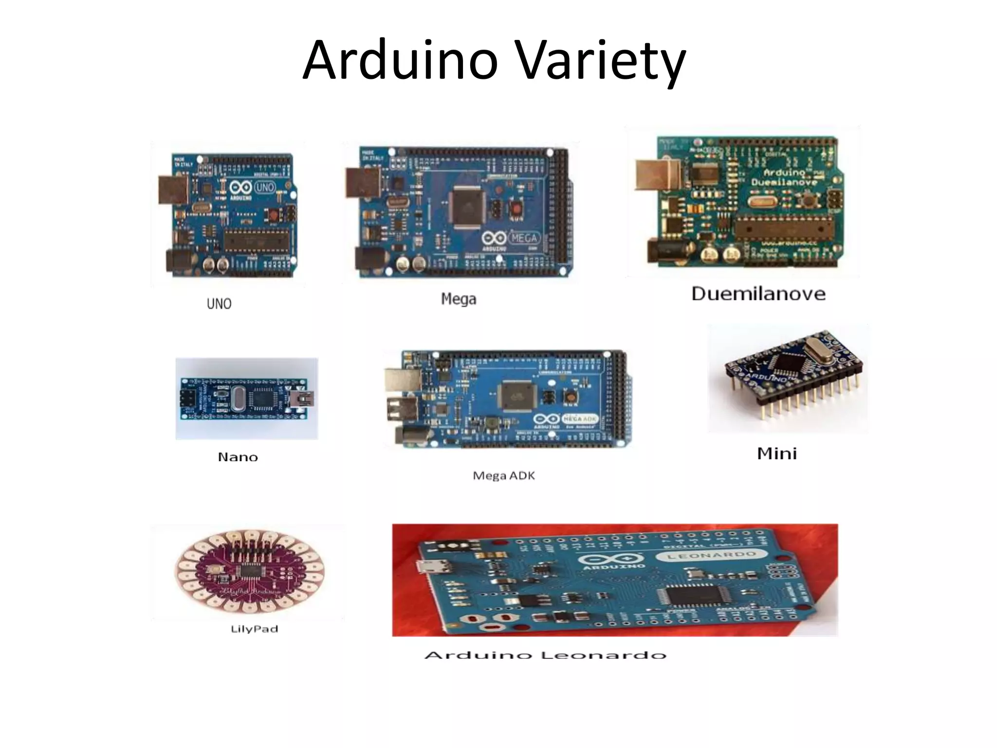
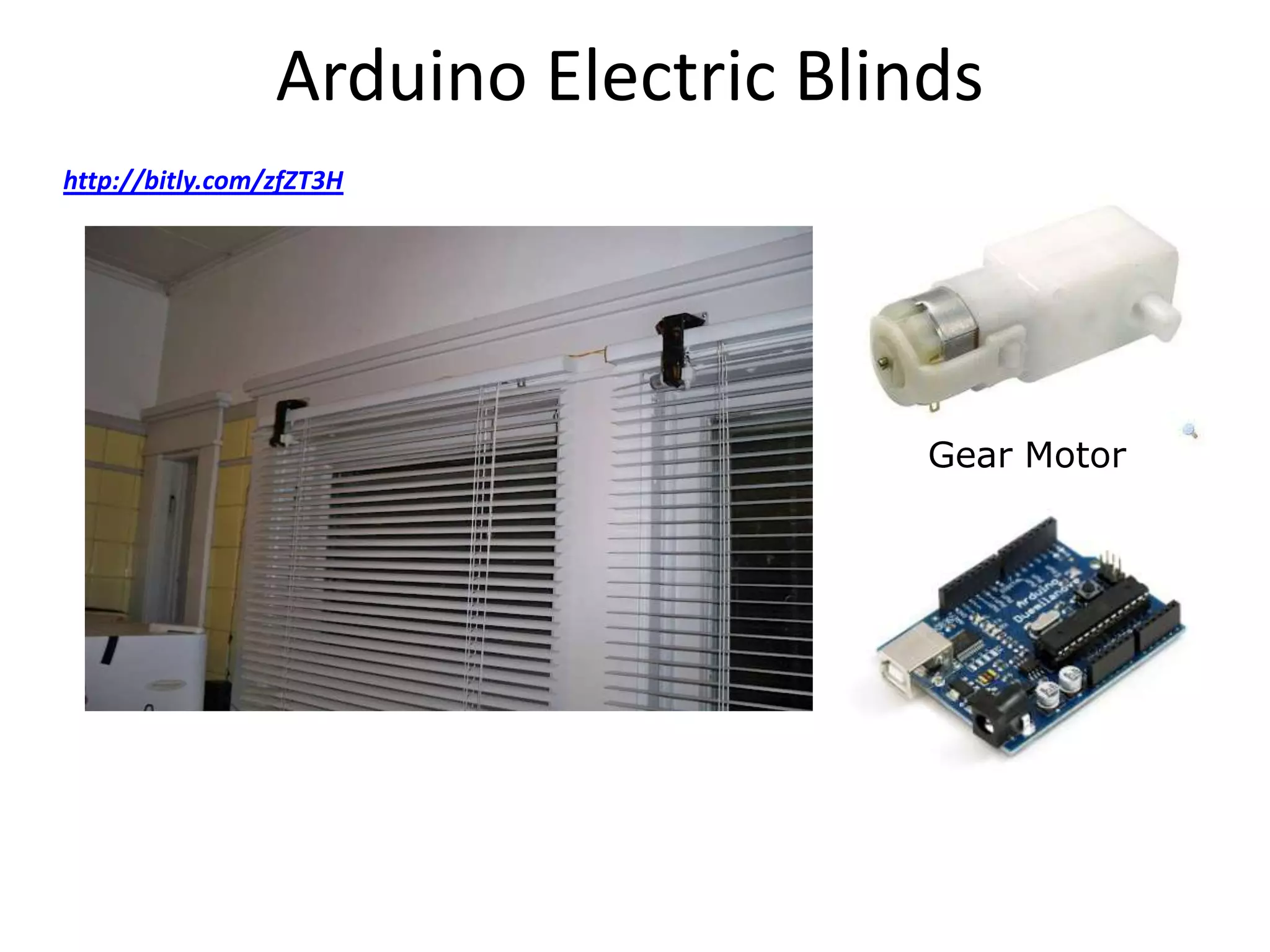
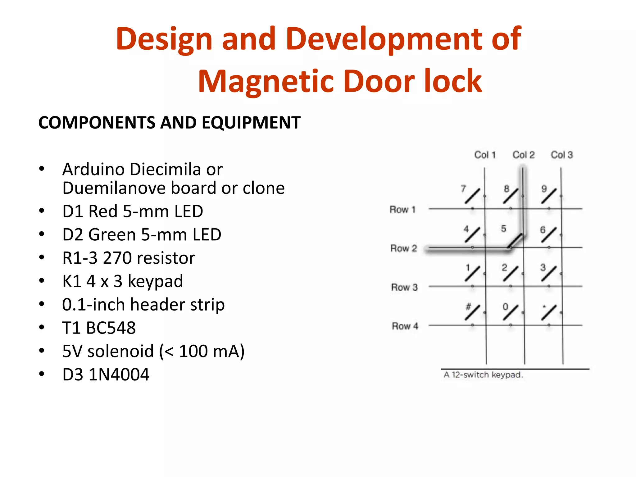
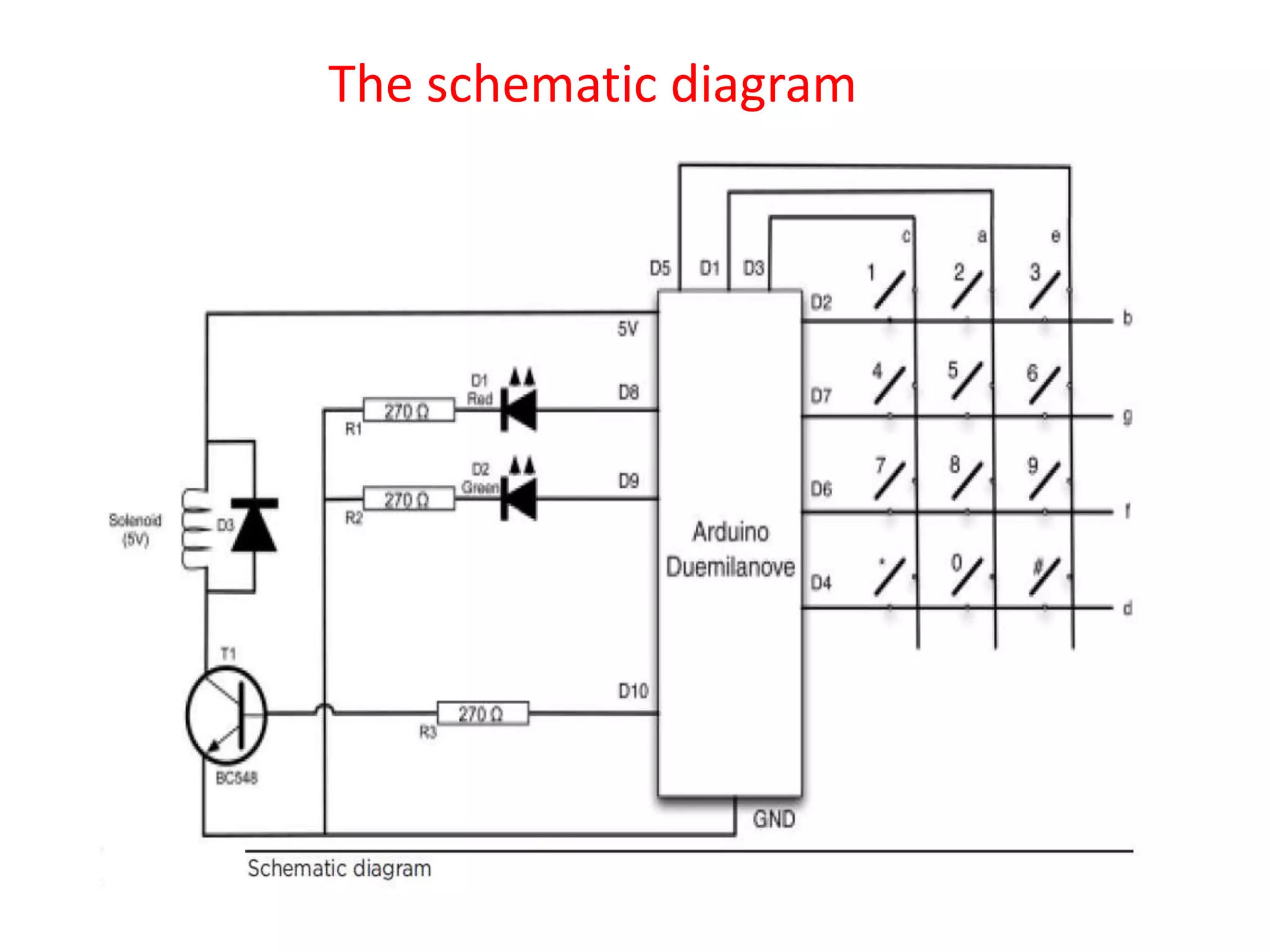
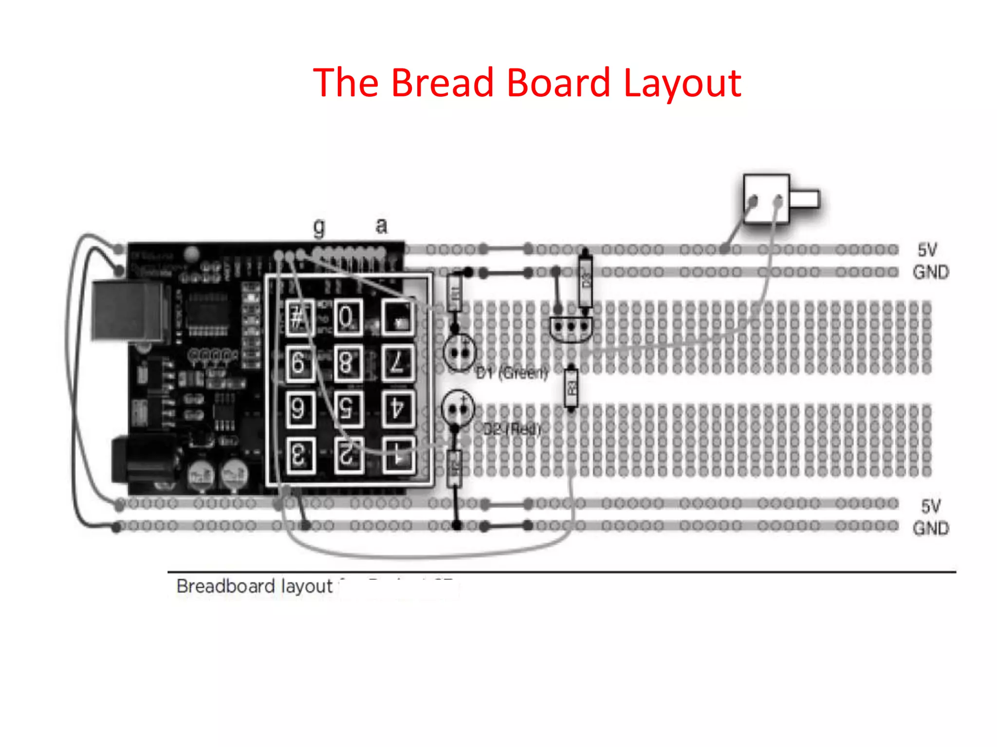
This document describes the design and implementation of a magnetic door lock system using an Arduino board. The system uses a keypad to enter a secret code, and unlocks a solenoid on the door when the correct code is entered. It provides status using LED lights. The system stores the code in EEPROM and can be programmed to a new code via the keypad. The document outlines the hardware components, circuit diagram, software code, and concludes with potential applications and extensions of the system.