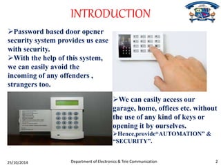
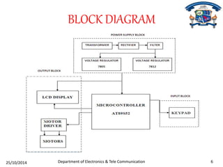
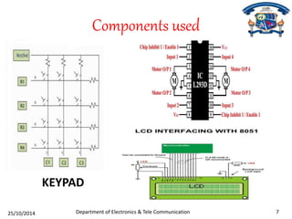
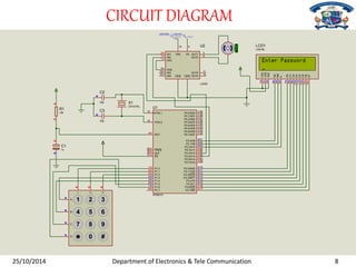
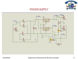
VIGNAN INSTITUTE OF TECHNOLOGY AND MANAGEMENT 
“MICRONTROLLER BASED ON PASSWORD PROTECTED DOOR 
Submitted by: 
OPENING SYSTEM” 
KISHAN KUMAR DAKUA Regd N o- 122130104 
AKANKHYA MOHANTY Regd No- 1101301065 
HEMANTA SAHU Regd No- 1221301025 
Under the Esteemed Guidance of: 
Prof. V.Srikanth 
DEPARTMENT OF ELECTRONICS & TELECOMMUNICATION ENGINEERING
CONTENTS 
1. Introduction 
2. Need of project 
3. Objective 
4. Components 
5. Block diagram 
6. Circuit diagram 
7. Applications 
8. Advantages 
9. Conclusion 
10.References 
Department of Electronics & Tele Communication 25/10/2014 1
INTRODUCTION 
Password based door opener 
security system provides us ease 
with security. 
With the help of this system, 
we can easily avoid the 
incoming of any offenders , 
strangers too. 
We can easily access our 
garage, home, offices etc. without 
the use of any kind of keys or 
opening it by ourselves. 
Hence,provide“AUTOMATION” & 
“SECURITY”. 
Department of Electronics & Tele Communication 25/10/2014 2
NEED OF PROJECT 
There are great varieties of 
digital code locks. Generally 
speaking, they can be 
classified into scores of type, 
such as electronic lock, 
fingerprint lock, card lock 
biological lock, etc. 
This kind of lock can 
avoiding the problems 
caused by the copying of 
keys. 
It is because the keys people 
carry have become burden most 
of the time, but by contrast 
people need only to remember a 
set of codes for electronics 
locks and don’t have to carry 
any key, thus freeing themselves 
from worries. 
Among them the most 
practical and the most 
popularized one come to 
digital code lock. 
On the premise that it’s safety is 
high, it’s another feature without 
key is getting more and more 
favour of people. 
25/10/2014 Department of Electronics & Tele Communication 3
OBJECTIVE 
To help users and 
give them favour 
to go anywhere. 
The 
objectives of 
our project 
are listed as 
above: 
To avoid any 
crimes especially 
stealing activities. 
To design a 
keyless door 
entry by using 
electronic digital 
lock code. 
Department of Electronics & Tele Communication 25/10/2014 4
COMPONENTS 
Hardware part : 
• 8051/8052 Microcontroller 
• LCD 
• Motor driver 
• Motor 
• Power Supply 
Software part : 
• Keil IDE software 
• Proteus 
25/10/2014 Department of Electronics & Tele Communication 5
BLOCK DIAGRAM 
Department of Electronics & Tele Communication 25/10/2014 6
Components used 
KEYPAD 
Department of Electronics & Tele Communication 25/10/2014 7
CIRCUIT DIAGRAM 
U1 
U2(VSS) U2(VS) 
2 
7 
1 
9 
10 
15 
XTAL1 
XTAL2 
19 
18 
RST 
PSEN 
ALE 
9 
29 
30 
EA 
31 
OUT1 
OUT2 
OUT3 
OUT4 
8 
VS 
GND GND 
P0.0/AD0 
U2 
L293D 
39 
P0.1/AD1 
38 
P0.2/AD2 
37 
P0.3/AD3 
36 
P0.4/AD4 
35 
P0.5/AD5 
34 
P0.6/AD6 
33 
P0.7/AD7 
32 
P1.0 
1 
P1.1 
2 
P1.2 
3 
P1.3 
4 
P1.4 
5 
P1.5 
6 
P1.6 
7 
P1.7 
8 
P2.0/A8 
P2.1/A9 
P2.2/A10 
P2.3/A11 
P2.4/A12 
P2.5/A13 
P2.6/A14 
P2.7/A15 
P3.0/RXD 
21 
22 
23 
24 
25 
26 
27 
28 
10 
P3.1/TXD 
11 
P3.2/INT0 
12 
P3.3/INT1 
13 
P3.4/T0 
14 
P3.5/T1 
P3.6/WR 
P3.7/RD 
15 
16 
17 
AT89C51 
D7 
D6 
14 
D5 
13 
D4 
12 
D3 
11 
D2 
10 
D1 
9 
D0 
8 
7 
E 
RW 
6 
RS 
5 
4 
LCD1 
LM016L 
VSS 
1 
VDD 
2 
VEE 
3 
R1 
10k 
C1 
1u 
C2 
33p 
C3 
33p 
X1 
CRYSTAL 
1 
2 
3 
1 2 3 
4 5 6 
7 8 9 
0 # 
A 
B 
C 
D 
0.00 
IN1 
3 
6 
11 
14 
IN2 
EN1 
EN2 
IN3 
IN4 
16 
VSS 
25/10/2014 Department of Electronics & Tele Communication 8
POWER SUPPLY 
25/10/2014 Department of Electronics & Tele Communication 9
Flowchart 
start 
Initialization of ports 
Assign ports for Keypad 
9 
Assign ports for LCD 
and Motor driver 
Assign variable “pswd” 
to store password 
Save the password in a variable 
“pswd” 
25/10/2014 Department of Electronics & Tele Communication 10
Enter the password using 
keypad(k) 
IF 
pswd 
=k 
IF 
C=4 
Door open 
C=C+1 
WAIT FOR 2min 
Y 
Y 
N 
N 
STOP 
Display on LCD 
“password matched” 
Y 
Display on LCD 
“password Wrong” 
25/10/2014 Department of Electronics & Tele Communication 11
CAMERA VIEW 
25/10/2014 Department of Electronics & Tele Communication 12
APPLICATION 
• Home access security. 
• Office access security. 
• Garage automation access. 
• Home automation access. 
25/10/2014 Department of Electronics & Tele Communication 13
ADVANTAGES 
• Simple installation. 
• Provide ease and automation. 
• Keyless system, hence no more worry of 
losing of keys. 
• Since, it is the system having password 
facility, provide security as well. 
25/10/2014 Department of Electronics & Tele Communication 14
CONCLUSION 
When we completed this 
project, we had learned 
and understand the 
process of constructing 
the Digital Code Lock which contained 
hardware and software 
development. We also 
know and understand 
the microcontroller PIC 
and how to implement it 
on my project. 
Our digital code lock 
performed as expected. 
We were able to 
implement all the 
functions specified in our 
proposal. 
This digital code lock is 
therefore particularly 
useful in applications 
such as hotel room door 
locks, residential 
housing and even office 
buildings. 
The biggest hurdle we had 
to overcome with this 
project was interfacing 
the microcontroller with 
the hardware 
components. 
25/10/2014 Department of Electronics & Tele Communication 15
references 
TEXT BOOKS: 
[1] The “8051 Microcontroller and Embedded Systems” by Muhammad Ali Mazidi 
and Janice Gillispe Mazidi, Pearson Education. 
[2] ATMEL 89S52 Data sheets 
REFERENCES: 
[1] http://www.sparkfun.com/datasheets/Components/DS1307.pdf 
[2] http://www.engineersgarage.com 
[3] http://www.zntu.edu.ua/base/lection/rpf/lib/zh03/8051_tutorial.pdf 
[4] http://electricly.com/at89s52-microcontroller 
[5] http://www.seeedstudio.com/wiki/Grove_-_RTC#Application_Ideas 
14/10/2014 Department of Electronics & Tele Communication 16
THANK YOU 
25/10/2014 Department of Electronics & Tele Communication 17

PASSWORD PROTECTED DOOR OPENING SYSTEM BY HEMANTA

  • 1.
    VIGNAN INSTITUTE OFTECHNOLOGY AND MANAGEMENT “MICRONTROLLER BASED ON PASSWORD PROTECTED DOOR Submitted by: OPENING SYSTEM” KISHAN KUMAR DAKUA Regd N o- 122130104 AKANKHYA MOHANTY Regd No- 1101301065 HEMANTA SAHU Regd No- 1221301025 Under the Esteemed Guidance of: Prof. V.Srikanth DEPARTMENT OF ELECTRONICS & TELECOMMUNICATION ENGINEERING
  • 2.
    CONTENTS 1. Introduction 2. Need of project 3. Objective 4. Components 5. Block diagram 6. Circuit diagram 7. Applications 8. Advantages 9. Conclusion 10.References Department of Electronics & Tele Communication 25/10/2014 1
  • 3.
    INTRODUCTION Password baseddoor opener security system provides us ease with security. With the help of this system, we can easily avoid the incoming of any offenders , strangers too. We can easily access our garage, home, offices etc. without the use of any kind of keys or opening it by ourselves. Hence,provide“AUTOMATION” & “SECURITY”. Department of Electronics & Tele Communication 25/10/2014 2
  • 4.
    NEED OF PROJECT There are great varieties of digital code locks. Generally speaking, they can be classified into scores of type, such as electronic lock, fingerprint lock, card lock biological lock, etc. This kind of lock can avoiding the problems caused by the copying of keys. It is because the keys people carry have become burden most of the time, but by contrast people need only to remember a set of codes for electronics locks and don’t have to carry any key, thus freeing themselves from worries. Among them the most practical and the most popularized one come to digital code lock. On the premise that it’s safety is high, it’s another feature without key is getting more and more favour of people. 25/10/2014 Department of Electronics & Tele Communication 3
  • 5.
    OBJECTIVE To helpusers and give them favour to go anywhere. The objectives of our project are listed as above: To avoid any crimes especially stealing activities. To design a keyless door entry by using electronic digital lock code. Department of Electronics & Tele Communication 25/10/2014 4
  • 6.
    COMPONENTS Hardware part: • 8051/8052 Microcontroller • LCD • Motor driver • Motor • Power Supply Software part : • Keil IDE software • Proteus 25/10/2014 Department of Electronics & Tele Communication 5
  • 7.
    BLOCK DIAGRAM Departmentof Electronics & Tele Communication 25/10/2014 6
  • 8.
    Components used KEYPAD Department of Electronics & Tele Communication 25/10/2014 7
  • 9.
    CIRCUIT DIAGRAM U1 U2(VSS) U2(VS) 2 7 1 9 10 15 XTAL1 XTAL2 19 18 RST PSEN ALE 9 29 30 EA 31 OUT1 OUT2 OUT3 OUT4 8 VS GND GND P0.0/AD0 U2 L293D 39 P0.1/AD1 38 P0.2/AD2 37 P0.3/AD3 36 P0.4/AD4 35 P0.5/AD5 34 P0.6/AD6 33 P0.7/AD7 32 P1.0 1 P1.1 2 P1.2 3 P1.3 4 P1.4 5 P1.5 6 P1.6 7 P1.7 8 P2.0/A8 P2.1/A9 P2.2/A10 P2.3/A11 P2.4/A12 P2.5/A13 P2.6/A14 P2.7/A15 P3.0/RXD 21 22 23 24 25 26 27 28 10 P3.1/TXD 11 P3.2/INT0 12 P3.3/INT1 13 P3.4/T0 14 P3.5/T1 P3.6/WR P3.7/RD 15 16 17 AT89C51 D7 D6 14 D5 13 D4 12 D3 11 D2 10 D1 9 D0 8 7 E RW 6 RS 5 4 LCD1 LM016L VSS 1 VDD 2 VEE 3 R1 10k C1 1u C2 33p C3 33p X1 CRYSTAL 1 2 3 1 2 3 4 5 6 7 8 9 0 # A B C D 0.00 IN1 3 6 11 14 IN2 EN1 EN2 IN3 IN4 16 VSS 25/10/2014 Department of Electronics & Tele Communication 8
  • 10.
    POWER SUPPLY 25/10/2014Department of Electronics & Tele Communication 9
  • 11.
    Flowchart start Initializationof ports Assign ports for Keypad 9 Assign ports for LCD and Motor driver Assign variable “pswd” to store password Save the password in a variable “pswd” 25/10/2014 Department of Electronics & Tele Communication 10
  • 12.
    Enter the passwordusing keypad(k) IF pswd =k IF C=4 Door open C=C+1 WAIT FOR 2min Y Y N N STOP Display on LCD “password matched” Y Display on LCD “password Wrong” 25/10/2014 Department of Electronics & Tele Communication 11
  • 13.
    CAMERA VIEW 25/10/2014Department of Electronics & Tele Communication 12
  • 14.
    APPLICATION • Homeaccess security. • Office access security. • Garage automation access. • Home automation access. 25/10/2014 Department of Electronics & Tele Communication 13
  • 15.
    ADVANTAGES • Simpleinstallation. • Provide ease and automation. • Keyless system, hence no more worry of losing of keys. • Since, it is the system having password facility, provide security as well. 25/10/2014 Department of Electronics & Tele Communication 14
  • 16.
    CONCLUSION When wecompleted this project, we had learned and understand the process of constructing the Digital Code Lock which contained hardware and software development. We also know and understand the microcontroller PIC and how to implement it on my project. Our digital code lock performed as expected. We were able to implement all the functions specified in our proposal. This digital code lock is therefore particularly useful in applications such as hotel room door locks, residential housing and even office buildings. The biggest hurdle we had to overcome with this project was interfacing the microcontroller with the hardware components. 25/10/2014 Department of Electronics & Tele Communication 15
  • 17.
    references TEXT BOOKS: [1] The “8051 Microcontroller and Embedded Systems” by Muhammad Ali Mazidi and Janice Gillispe Mazidi, Pearson Education. [2] ATMEL 89S52 Data sheets REFERENCES: [1] http://www.sparkfun.com/datasheets/Components/DS1307.pdf [2] http://www.engineersgarage.com [3] http://www.zntu.edu.ua/base/lection/rpf/lib/zh03/8051_tutorial.pdf [4] http://electricly.com/at89s52-microcontroller [5] http://www.seeedstudio.com/wiki/Grove_-_RTC#Application_Ideas 14/10/2014 Department of Electronics & Tele Communication 16
  • 18.
    THANK YOU 25/10/2014Department of Electronics & Tele Communication 17