Downloaded 387 times

![Function to identify a key pressed
//connect colum with lower nibble and rows with upper nibble
#define key_port PORTA
#define key_ddr DDRA
#define key_pin PINA
unsigned char keypad[4][4]={'7','8','9','/',
'4','5','6','*',
'1','2','3','-',
'c','0','=','+'};
char takekey()
{
unsigned char row,colum;
char key;
key_ddr=0xf0;
key_port=0xff;
do
{
key_port&=0x0f;
colum=(key_pin&0x0f);
}while(colum!=0x0f);
do
{
do
{
_delay_ms(1);
key_port&=0x0f;
colum=(key_pin&0x0f);
}while(colum==0x0f);
_delay_ms(1);
key_port&=0x0f;](https://image.slidesharecdn.com/basicstandardcalculator-141209062820-conversion-gate02/75/Basic-standard-calculator-5-2048.jpg)

![if(colum==0x0e)
key=keypad[row][0];
else if(colum==0x0d)
key=keypad[row][1];
else if(colum==0x0b)
key=keypad[row][2];
else
key=keypad[row][3];
return(key);
}
Interfacing 2x16 LCD with microcontroller (in 4 bit mode)
LCD interfacing with atmega 16](https://image.slidesharecdn.com/basicstandardcalculator-141209062820-conversion-gate02/75/Basic-standard-calculator-7-2048.jpg)


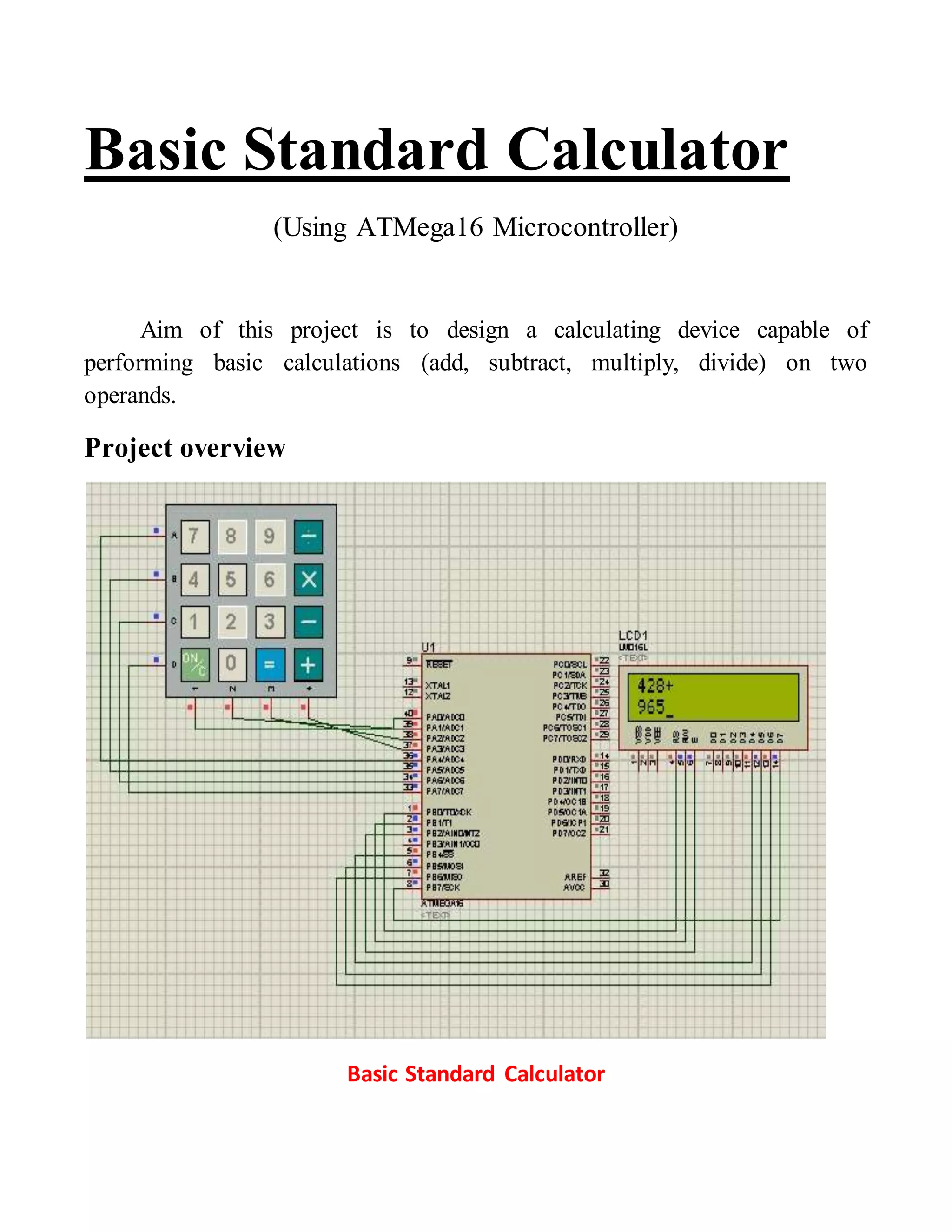
This document describes the design of a basic standard calculator using an ATMega16 microcontroller. The calculator can perform basic arithmetic operations of addition, subtraction, multiplication and division on two operands using a 4x4 keypad for input and a 2x16 LCD for output display. The microcontroller is programmed to read keypad input, perform calculations and display results on the LCD. It provides code examples for interfacing the keypad and LCD with the microcontroller and implementing the calculator functionality.