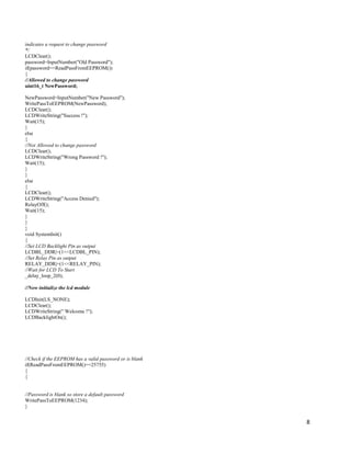
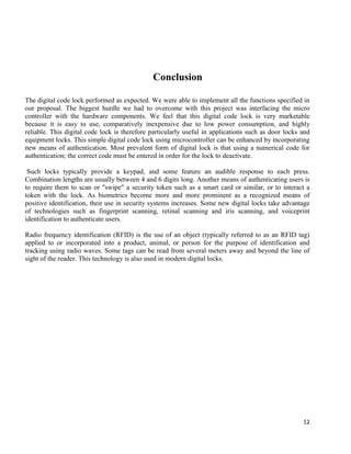
The document describes the hardware and software components of a password-based access control system using a microcontroller, including a keypad for entering passwords, an LCD display, and codes for comparing entered passwords to a stored password and controlling an output to trigger a relay if the passwords match. The system continuously monitors the keypad, compares entered passwords to the stored password, and allows access by turning on an LED or unlocking a device if the passwords match or displays an error message if they do not match.
![14
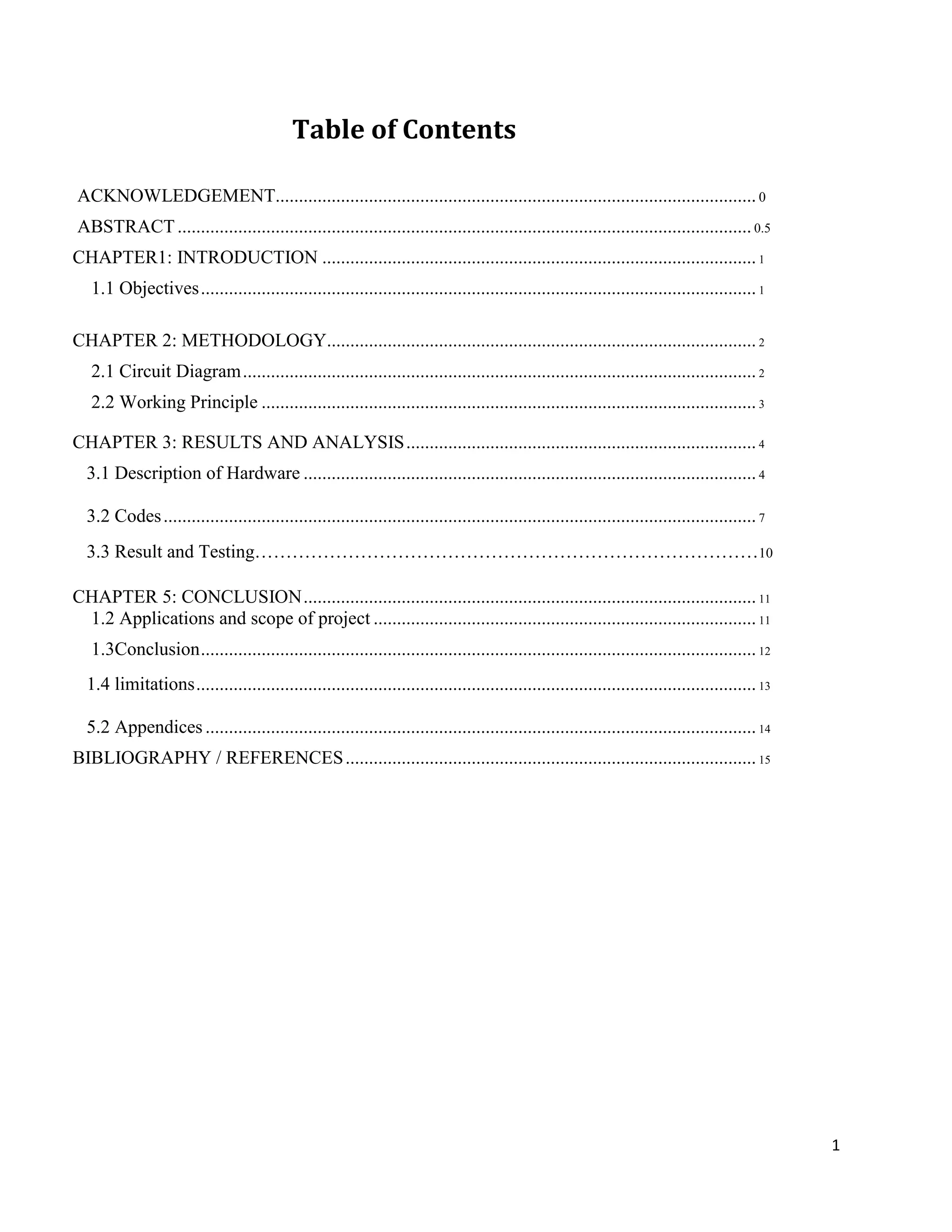
LCD KEYPAD
BIBLIOGRAPHY / REFERENCES
Theraja B.L., Theraja A.K., A textbook of electrical technology, 21st
Ed., S. Chand and
Company, New Delhi, India, 1999.
Automated Technologies, 2006, 9, p. 55-62 [online]. Available at:
http://www.lejpt.academicdirect.org/A09/055_062.pdf
ATmega8 tutorials [online]. Available at: http://www.electroniclab.com, 20012.
Microcontroller tutorials [online]. Available at: http://www.google.com, 2015.
Smart code locks using AVR, 2008, [online]. Available at:
http://extremeelectronics.co.in/avrprojects/avrproject/atmega8basedsmartcodelock/
ATmega 328P datasheet http://www.atmel.com/Images/doc8161.pdf.
Jeremy Blum ,” Exploring Arduino: Tools and Techniques for Engineering Wizardry”,
Wiley publishers,4th edition(2004).
LCD 16*2 datasheet http://www.engineersgarage.com/electronic-components/16x2-lcd-
module-datasheet.
http://www.instructables.com/id/Password-Lock-with-Arduino/](https://image.slidesharecdn.com/report-200311104205/85/Password-Based-Access-Control-System-using-Microcontroller-14-320.jpg)


![Embedded System[586]](https://cdn.slidesharecdn.com/ss_thumbnails/viisemesterindustrialtrainingreportpawan586-171104035355-thumbnail.jpg?width=640&height=640&fit=bounds)


![[Deck] What's New in Spark-Iceberg Integration via DSV2.pptx](https://cdn.slidesharecdn.com/ss_thumbnails/deckwhatsnewinspark-icebergintegrationviadsv2-260210005337-25955b12-thumbnail.jpg?width=640&height=640&fit=bounds)


