Downloaded 178 times
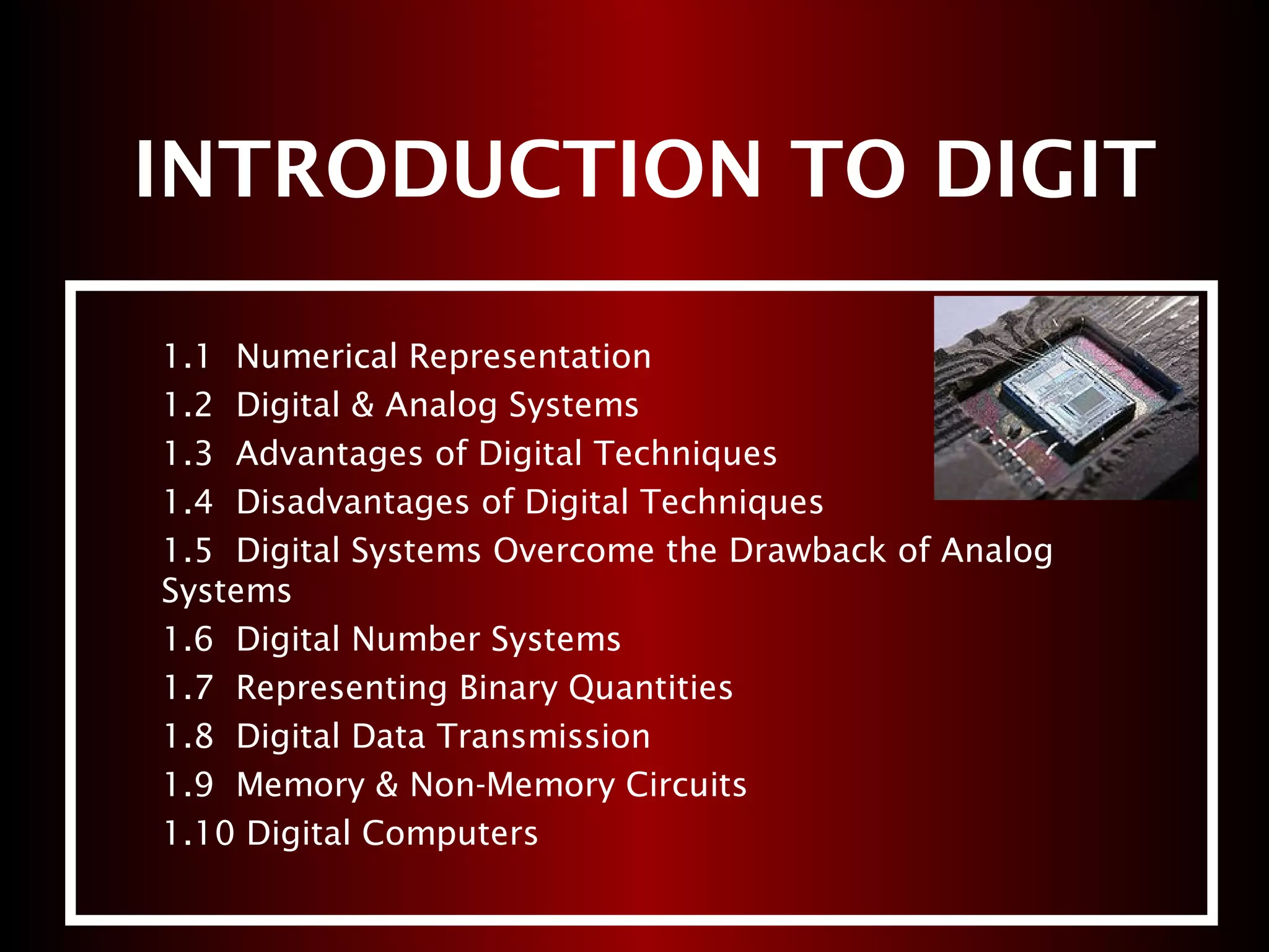
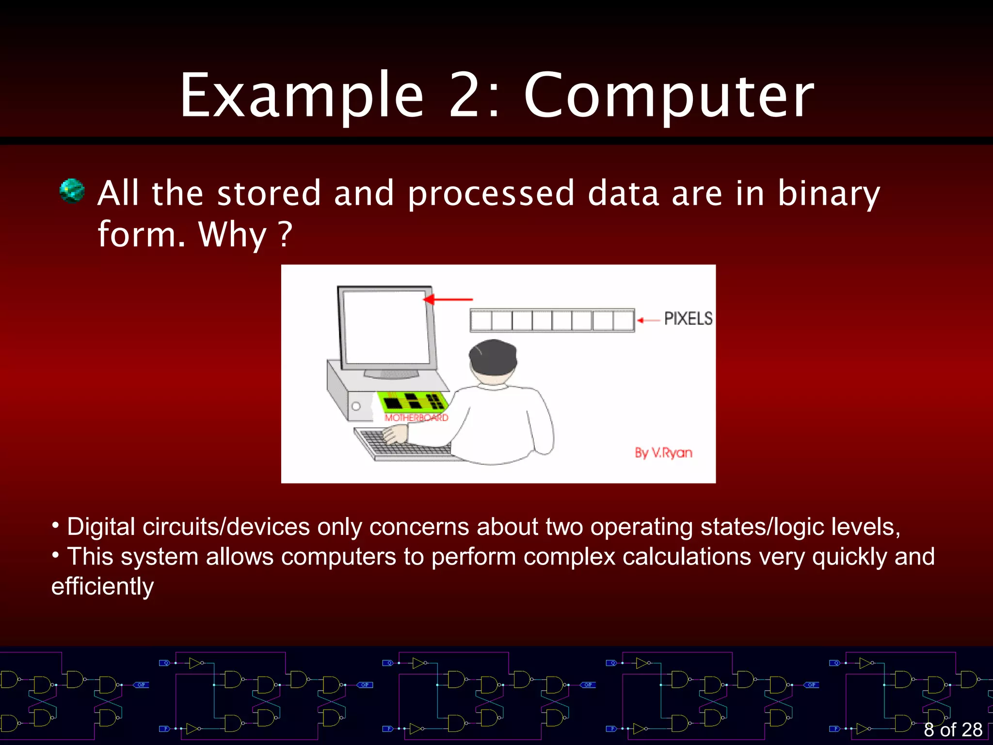
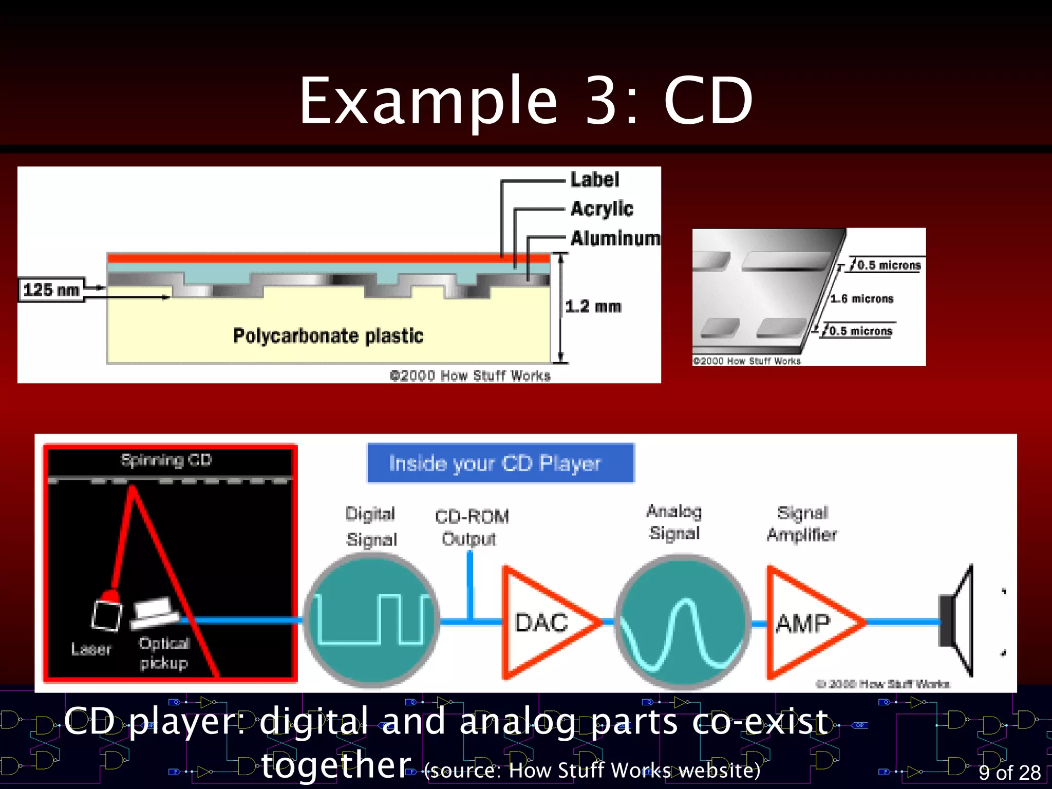
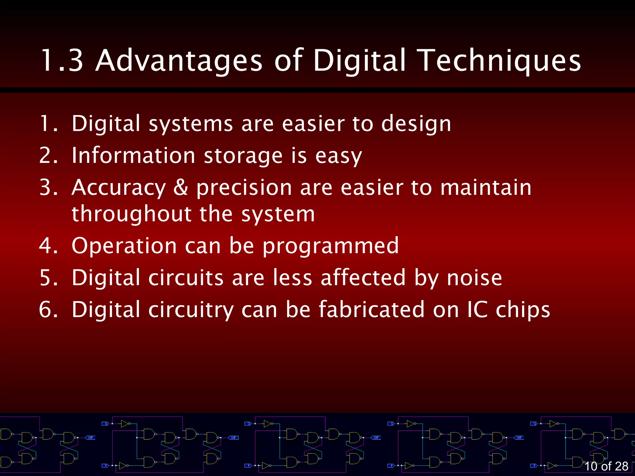
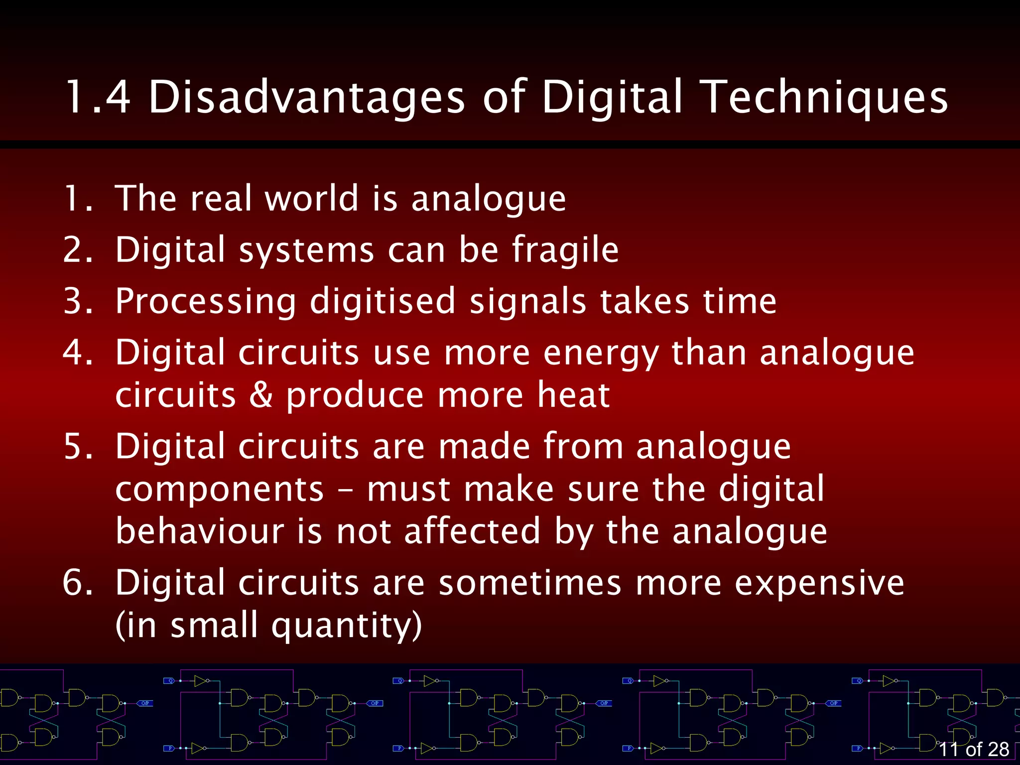
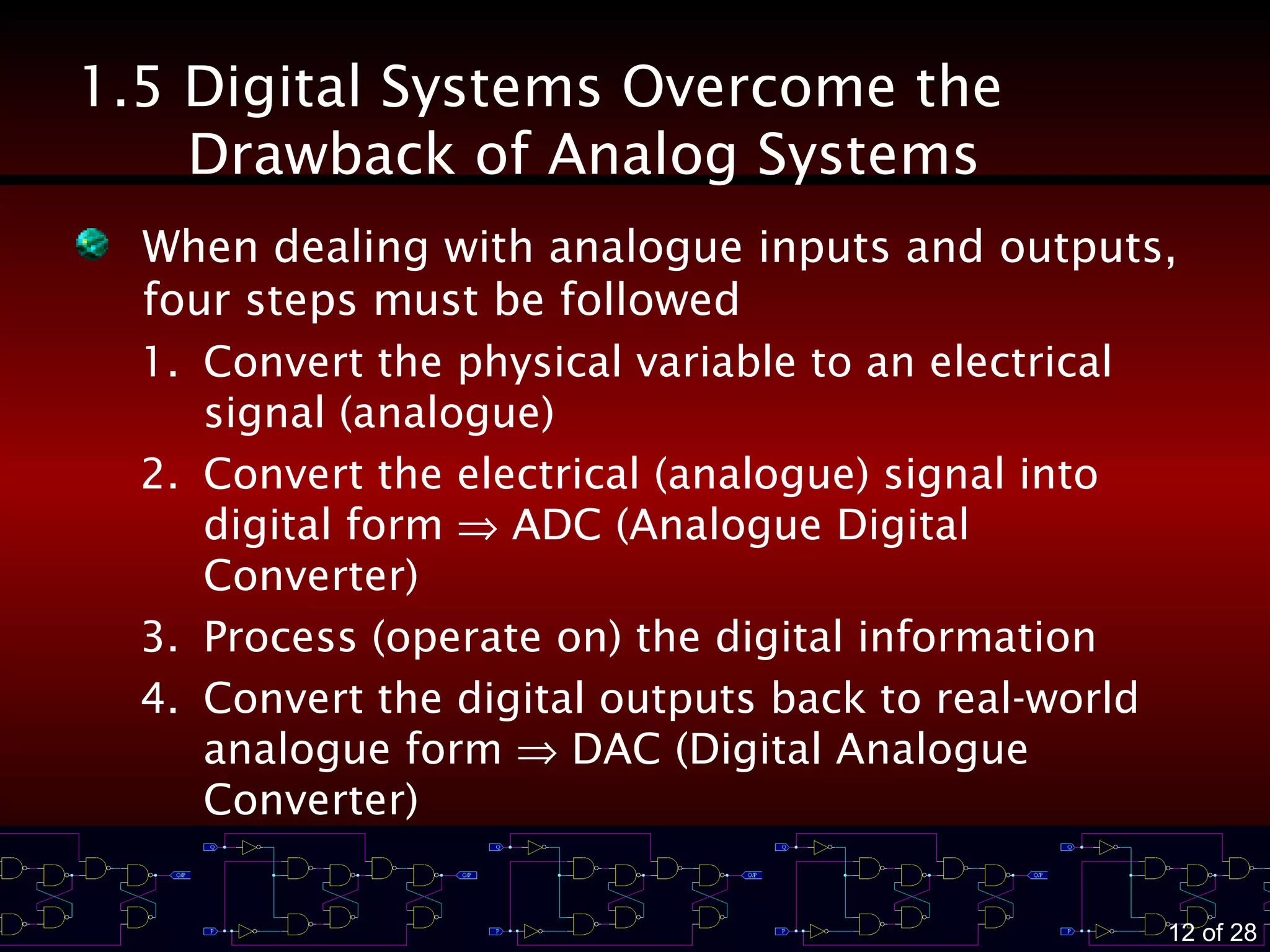
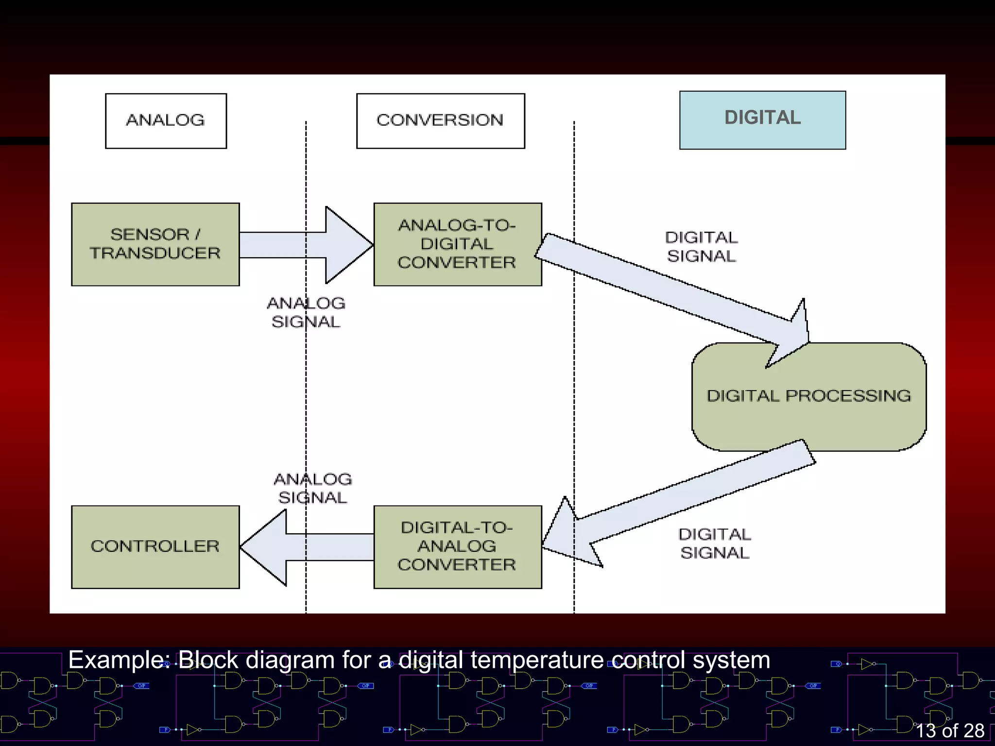
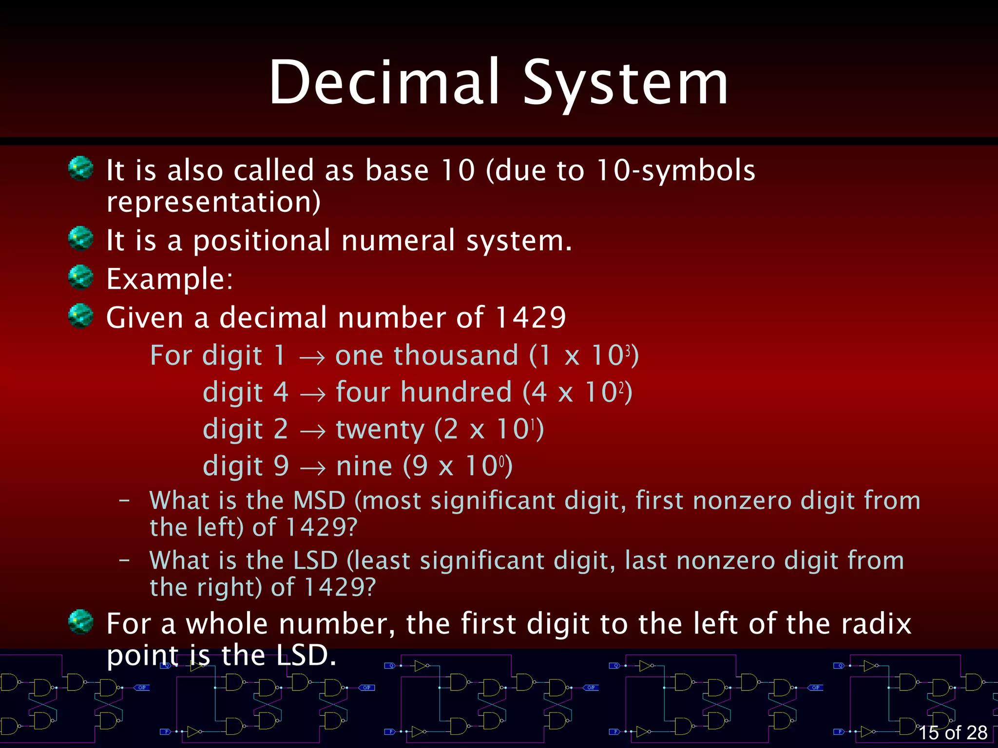
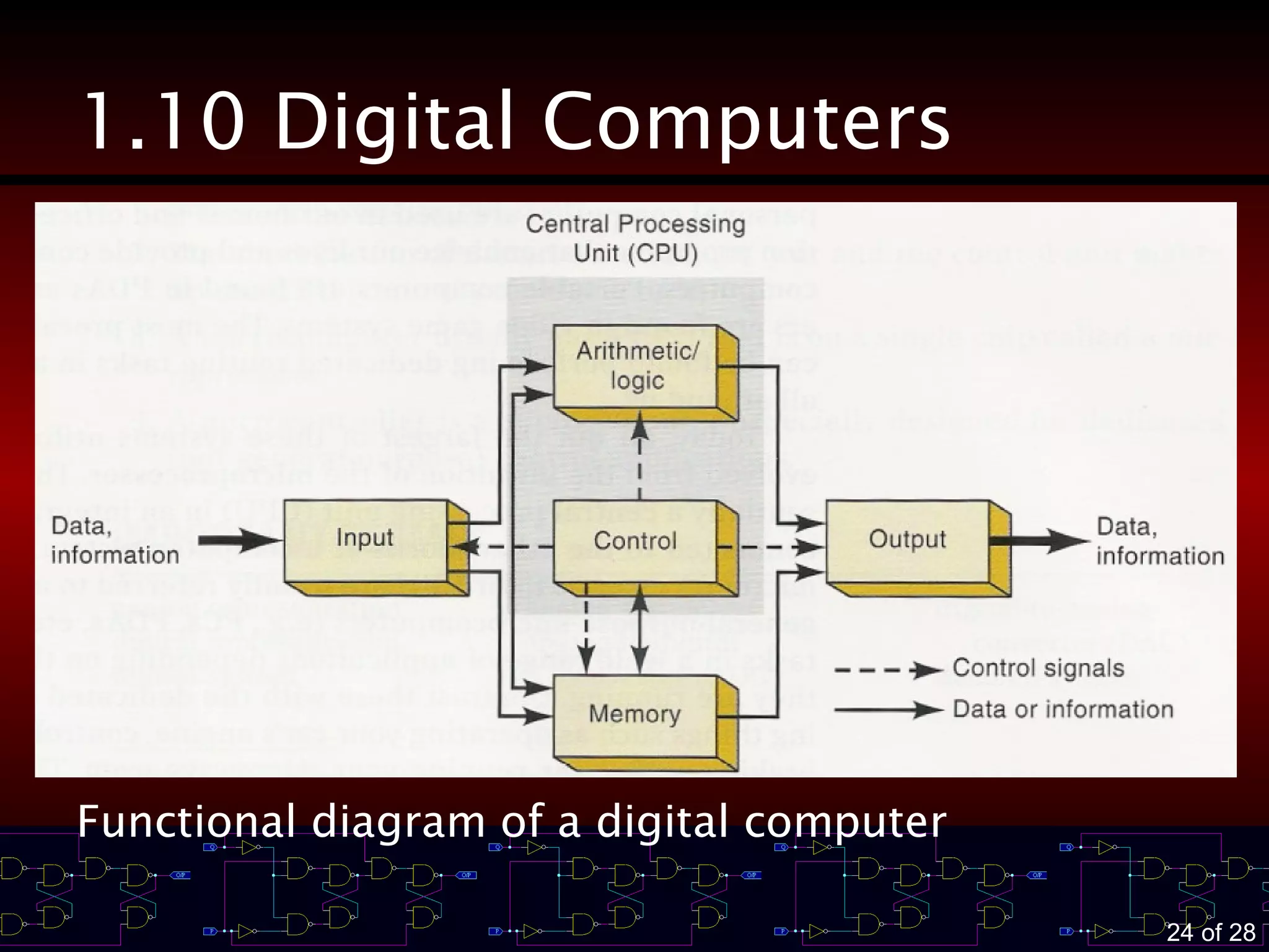
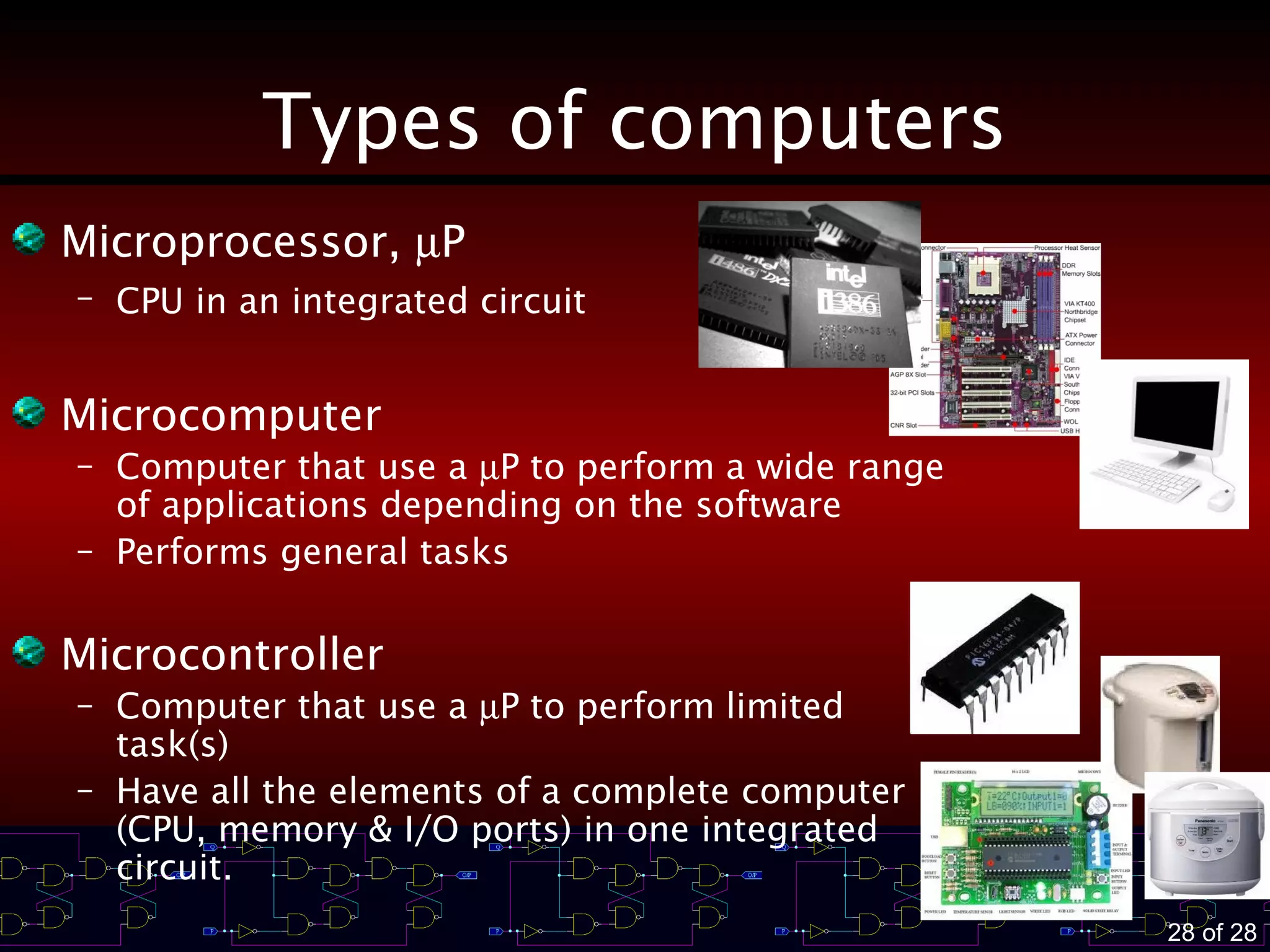

This document provides an introduction to digital systems and concepts. It defines analog and digital representations, and discusses the advantages and disadvantages of digital techniques compared to analog. It also describes digital number systems like binary and decimal, how binary quantities are represented, and methods for digital data transmission and storage in memory. Finally, it outlines the major components of a digital computer including the arithmetic logic unit, memory, input/output, and control unit.


![DE and LD [Autosave gyideffgfd] (1).pptx](https://cdn.slidesharecdn.com/ss_thumbnails/deandldautosaved1-241217121920-14134e9a-thumbnail.jpg?width=640&height=640&fit=bounds)