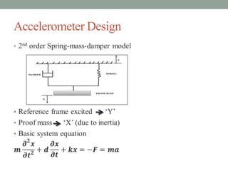
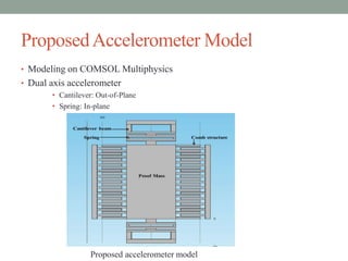
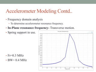
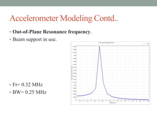
A Novel Approach to Design Dual
Axis MEMS Capacitive
Accelerometer
Authors:
Prashant Singh, Pooja Srivastava
Student, Dept. of Microelectronics
Indian Institute of Information Technology-Allahabad
Presented by:
Prashant Singh
Outline
• Definition
• MEMS
• Accelerometer
• Accelerometer classification
• Capacitive Accelerometer
• Accelerometer design
• Proposed Accelerometer Model
• Simulation Results
• Proof Mass Support Modeling
• Accelerometer Modeling

• Results and Conclusion
• References
Definition
• MEMS
• Micro-Electro-mechanical-system
• Integration of mechanical unit, electrical unit, sensor and
actuator on a single substrate.
• Accelerometer
• Inertial sensor
• Newton’s 1st law (Mass of inertia)

• Used to measure: (i) Acceleration,

(ii) Displacement,
(iii) Force
(iv) Inclination angle
Accelerometer Classification
• Fabrication Technique:
• Surface Micromachining- additive process
• Bulk Micromachining- subtractive process

• Sensing Technique
• Read out principle

• Displacement based: Capacitive
Tunneling
Optical
Hall effect
Thermal
Magnetic

• Stress based: Piezoelectric
Piezoresistive
Capacitive Accelerometer
• Based on Change in capacitance between Comb fingers.
• {Capacitance change} α {Force applied on Proof Mass}
• Comb structure

Large capacitance value

• Advantages
• High resolution
• Good DC response
• Linear output
• low power dissipation
• Easy incorporation with CMOS
Accelerometer Design
•
Proposed Accelerometer Model
• Modeling on COMSOL Multiphysics
• Dual axis accelerometer
• Cantilever: Out-of-Plane
• Spring: In-plane

Proposed accelerometer model
Simulation Results (proof mass support modeling)
•
Parameters

Beam (um)

Spring (um)

Length

20

100

Width

10

5

Height

10

10
Resonance Frequency for Spring support
• Resonance frequency depends only on Spring parameters.
• Beam has no effect on resonance frequency.

• Resonance frequency=1.75 MHz
• Bandwidth= 1 MHz
Spring support Modeling
•

Effect of Spring flexure height on free
point displacement

•

Effect of Spring flexure height on
Resonance frequency
Resonance Frequency for Beam support
• Resonance frequency depends on beam as well as

Spring parameters.

• Resonance frequency=1.1 MHz
• Bandwidth= 1 MHz
Spring support Modeling
•

Effect of Beam flexure height on
free point displacement

•

Effect of Beam flexure height on
Resonance frequency
Accelerometer Modeling
• Accelerometer Parameters
Parameters

Comb

Proof mass

Length(µm)

-

200

Width(µm)

-

100

Finger length(µm)

50

-

Finger width(µm)

5

-

Finger overlap(µm) 2.5

-

Finger gap(µm)

40

-

Capacitor pair

52

-

Height

10

10
Accelerometer Modeling Contd..
•
Accelerometer Modeling Contd..
• Frequency domain analysis
• To determine accelerometer resonance frequency.
• In-Plane resonance frequency- Transverse motion.
• Spring support in use.

• Fr=0.3 MHz
• BW= 0.4 MHz
Accelerometer Modeling Contd..
• Out-of-Plane Resonance frequency.
• Beam support in use.

• Fr= 0.32 MHz
• BW= 0.25 MHz
Results and Conclusion
• Dual Axis accelerometer is designed.
• In-Plane operation
• Spring support in use.
• Fr= 0.3 MHz
• BW= 0.4 Mhz
• Out-of-Plane operation
• Cantilever beam support in use
• Fr= 0.32 MHz
• BW= 0.25 MHz
• Application
• Moderate frequency operation
• Military
References
• G.M. Rebeiz, J.B. Muldavin, "RF MEMS switches and switch
•
•
•
•
•

circuits“, Microwave Magazine, IEEE , vol.2, no.4, pp.59-71, 2001.
S. Pacheco, et al., Microwave and Optoelectronics Conference, pp.
770-777, 2007.
http://www.memsnet.org/mems/what-is.html.
B.V. Amini, F. Ayazi, “A 2.5-V 14-bit CMOS SOI capacitive
accelerometer”, IEEE Solid-State Circuits 39(12):2467–2476, 2004.
G. Kovacs, Micromachined Transducers Sourcebook; New York:
McGraw Hill, 1998.
Chi Yuan Lee, Guan Wei Wu, Wei Jung Hsieh, “Fabrication of micro
sensors on a flexible substrate”, Sensors and Actuators,(2008).
Thank You

Dual axis accelerometer paper 157

  • 1.
    A Novel Approachto Design Dual Axis MEMS Capacitive Accelerometer Authors: Prashant Singh, Pooja Srivastava Student, Dept. of Microelectronics Indian Institute of Information Technology-Allahabad Presented by: Prashant Singh
  • 2.
    Outline • Definition • MEMS •Accelerometer • Accelerometer classification • Capacitive Accelerometer • Accelerometer design • Proposed Accelerometer Model • Simulation Results • Proof Mass Support Modeling • Accelerometer Modeling • Results and Conclusion • References
  • 3.
    Definition • MEMS • Micro-Electro-mechanical-system •Integration of mechanical unit, electrical unit, sensor and actuator on a single substrate. • Accelerometer • Inertial sensor • Newton’s 1st law (Mass of inertia) • Used to measure: (i) Acceleration, (ii) Displacement, (iii) Force (iv) Inclination angle
  • 4.
    Accelerometer Classification • FabricationTechnique: • Surface Micromachining- additive process • Bulk Micromachining- subtractive process • Sensing Technique • Read out principle • Displacement based: Capacitive Tunneling Optical Hall effect Thermal Magnetic • Stress based: Piezoelectric Piezoresistive
  • 5.
    Capacitive Accelerometer • Basedon Change in capacitance between Comb fingers. • {Capacitance change} α {Force applied on Proof Mass} • Comb structure Large capacitance value • Advantages • High resolution • Good DC response • Linear output • low power dissipation • Easy incorporation with CMOS
  • 6.
  • 7.
    Proposed Accelerometer Model •Modeling on COMSOL Multiphysics • Dual axis accelerometer • Cantilever: Out-of-Plane • Spring: In-plane Proposed accelerometer model
  • 8.
    Simulation Results (proofmass support modeling) • Parameters Beam (um) Spring (um) Length 20 100 Width 10 5 Height 10 10
  • 9.
    Resonance Frequency forSpring support • Resonance frequency depends only on Spring parameters. • Beam has no effect on resonance frequency. • Resonance frequency=1.75 MHz • Bandwidth= 1 MHz
  • 10.
    Spring support Modeling • Effectof Spring flexure height on free point displacement • Effect of Spring flexure height on Resonance frequency
  • 11.
    Resonance Frequency forBeam support • Resonance frequency depends on beam as well as Spring parameters. • Resonance frequency=1.1 MHz • Bandwidth= 1 MHz
  • 12.
    Spring support Modeling • Effectof Beam flexure height on free point displacement • Effect of Beam flexure height on Resonance frequency
  • 13.
    Accelerometer Modeling • AccelerometerParameters Parameters Comb Proof mass Length(µm) - 200 Width(µm) - 100 Finger length(µm) 50 - Finger width(µm) 5 - Finger overlap(µm) 2.5 - Finger gap(µm) 40 - Capacitor pair 52 - Height 10 10
  • 14.
  • 15.
    Accelerometer Modeling Contd.. •Frequency domain analysis • To determine accelerometer resonance frequency. • In-Plane resonance frequency- Transverse motion. • Spring support in use. • Fr=0.3 MHz • BW= 0.4 MHz
  • 16.
    Accelerometer Modeling Contd.. •Out-of-Plane Resonance frequency. • Beam support in use. • Fr= 0.32 MHz • BW= 0.25 MHz
  • 17.
    Results and Conclusion •Dual Axis accelerometer is designed. • In-Plane operation • Spring support in use. • Fr= 0.3 MHz • BW= 0.4 Mhz • Out-of-Plane operation • Cantilever beam support in use • Fr= 0.32 MHz • BW= 0.25 MHz • Application • Moderate frequency operation • Military
  • 18.
    References • G.M. Rebeiz,J.B. Muldavin, "RF MEMS switches and switch • • • • • circuits“, Microwave Magazine, IEEE , vol.2, no.4, pp.59-71, 2001. S. Pacheco, et al., Microwave and Optoelectronics Conference, pp. 770-777, 2007. http://www.memsnet.org/mems/what-is.html. B.V. Amini, F. Ayazi, “A 2.5-V 14-bit CMOS SOI capacitive accelerometer”, IEEE Solid-State Circuits 39(12):2467–2476, 2004. G. Kovacs, Micromachined Transducers Sourcebook; New York: McGraw Hill, 1998. Chi Yuan Lee, Guan Wei Wu, Wei Jung Hsieh, “Fabrication of micro sensors on a flexible substrate”, Sensors and Actuators,(2008).
  • 19.