Digital signal processing realization of FIR filters
1.
19E602 – DIGITALSIGNAL PROCESSING
PRESENTED BY
AKALYA – 22E104
GANASRI – 22E117
MADHUMITHA – 22E131
MEHALAN – 22E132
VYSHALI – 22E162
REALIZATION OF FIR FILTERS
2.
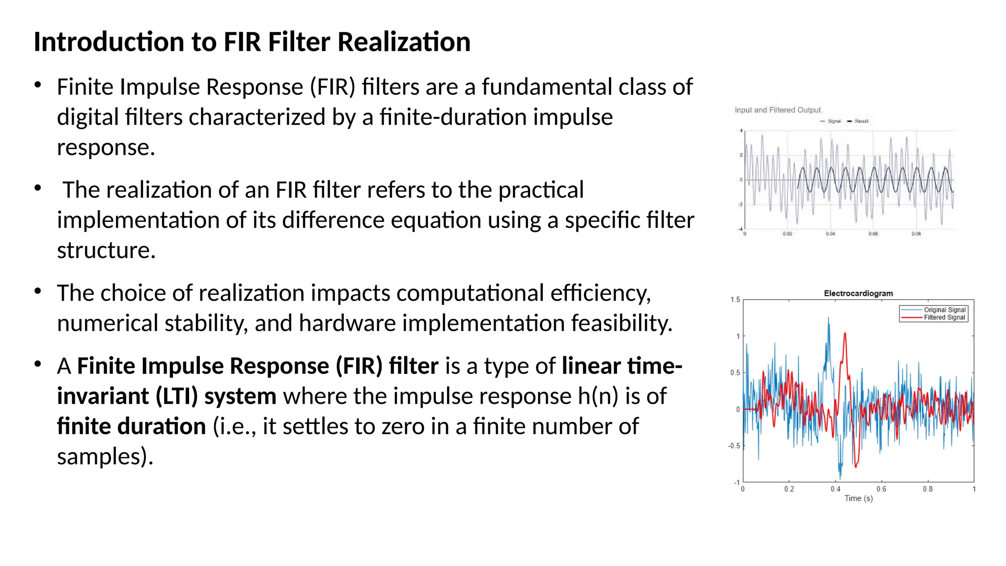
Introduction to FIRFilter Realization
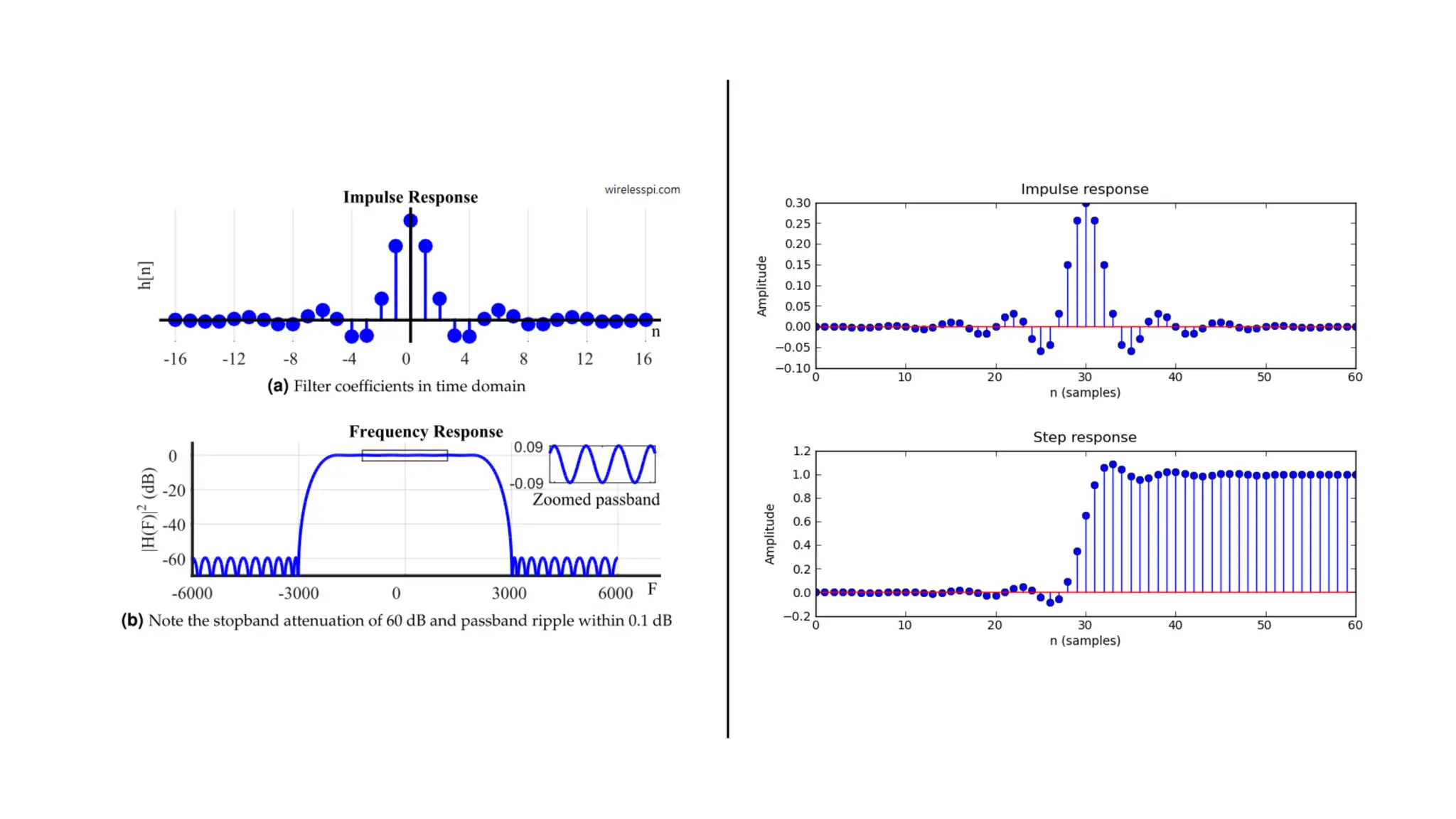
• Finite Impulse Response (FIR) filters are a fundamental class of
digital filters characterized by a finite-duration impulse
response.
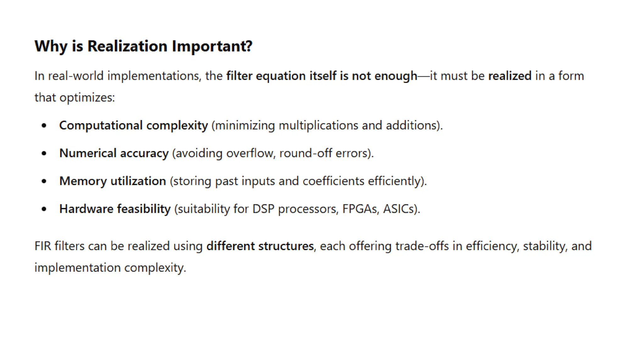
• The realization of an FIR filter refers to the practical
implementation of its difference equation using a specific filter
structure.
• The choice of realization impacts computational efficiency,
numerical stability, and hardware implementation feasibility.
• A Finite Impulse Response (FIR) filter is a type of linear time-
invariant (LTI) system where the impulse response h(n) is of
finite duration (i.e., it settles to zero in a finite number of
samples).
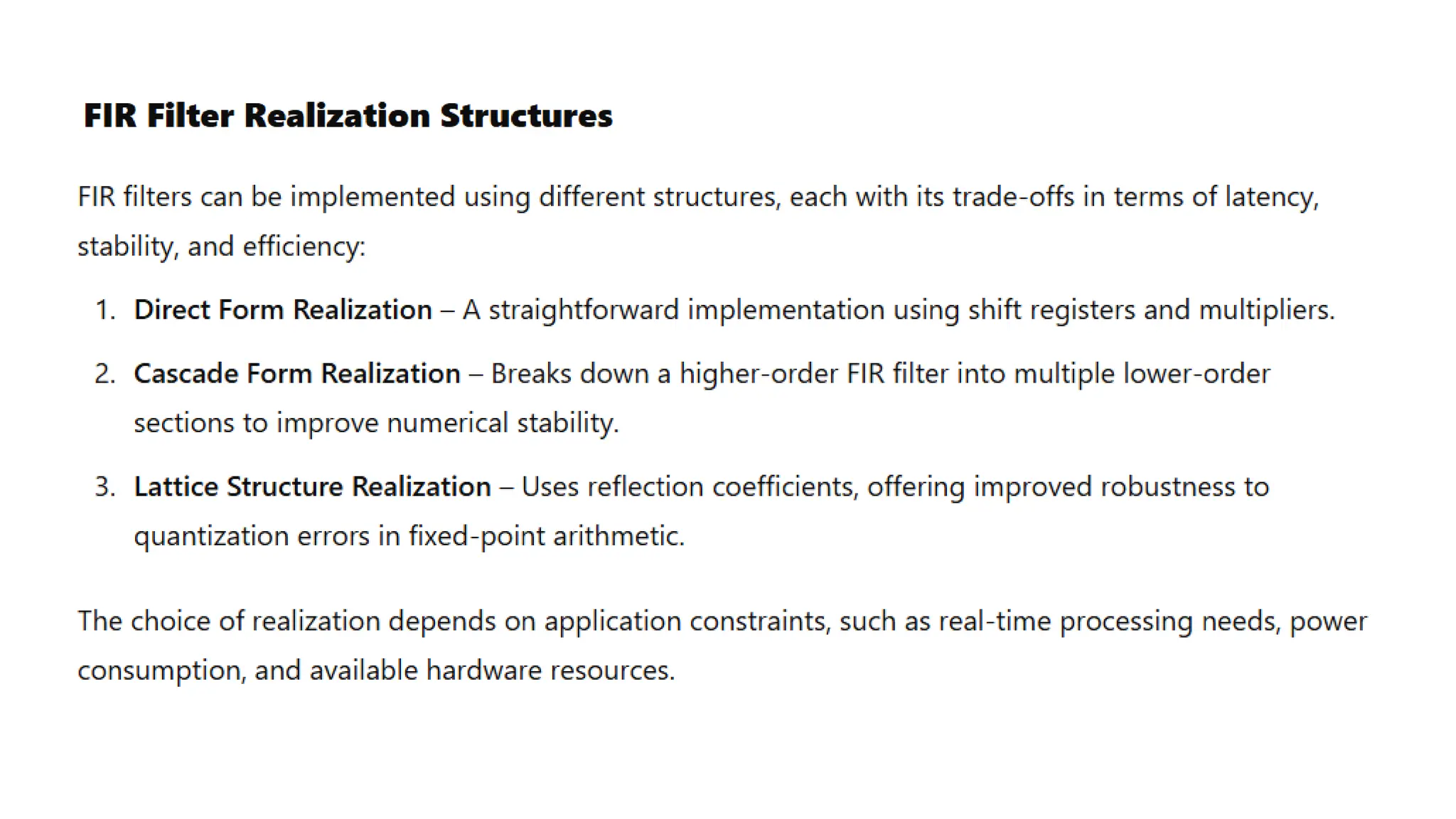
DIRECT FORM
• Thedirect form of a Finite Impulse Response (FIR) filter refers to its
straightforward implementation based on the difference equation.
• This is called “direct form” because it is a direct implementation of
the convolution operation.
• The number of delays is equal to the order of the filter, hence this
structure is canonic.
• The direct-form structure is directly obtained from the
difference equation.
11.
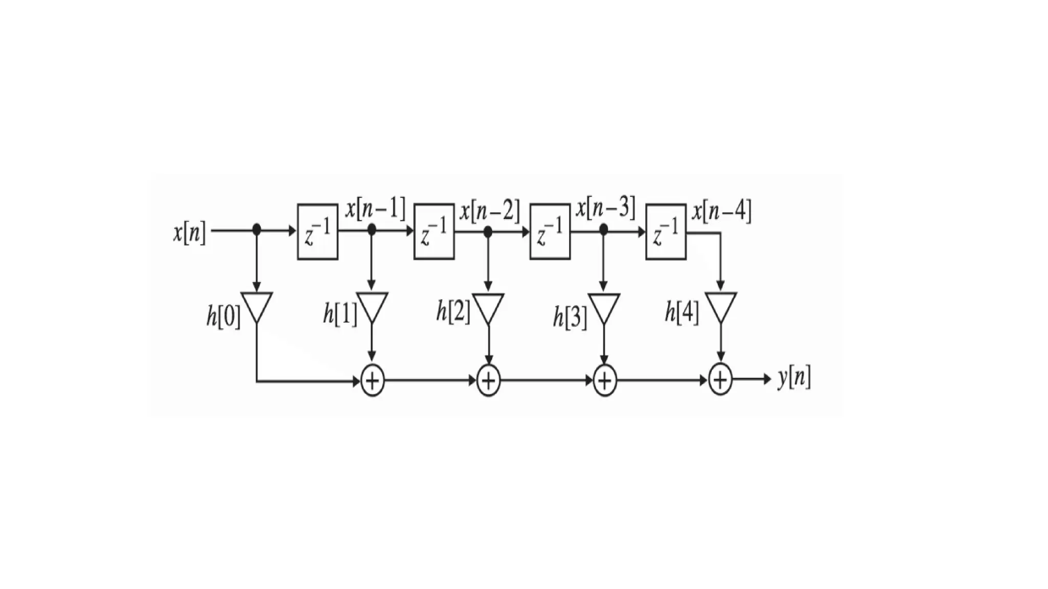
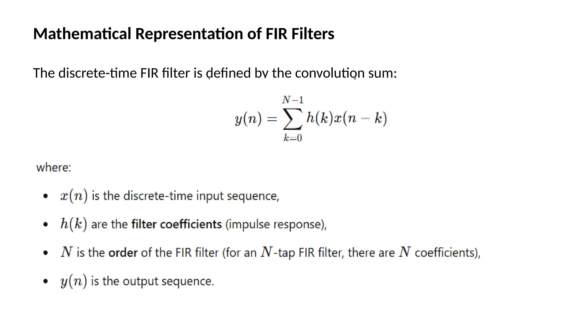
• For anFIR filter of order N, the output y[n] is computed as a
weighted sum of the current and past input samples:
y[n] =
• where:
x[n] is the input signal,
y[n] is the output signal,
h[k] represents the FIR filter coefficients (impulse response),
N is the order of the filter.
13.
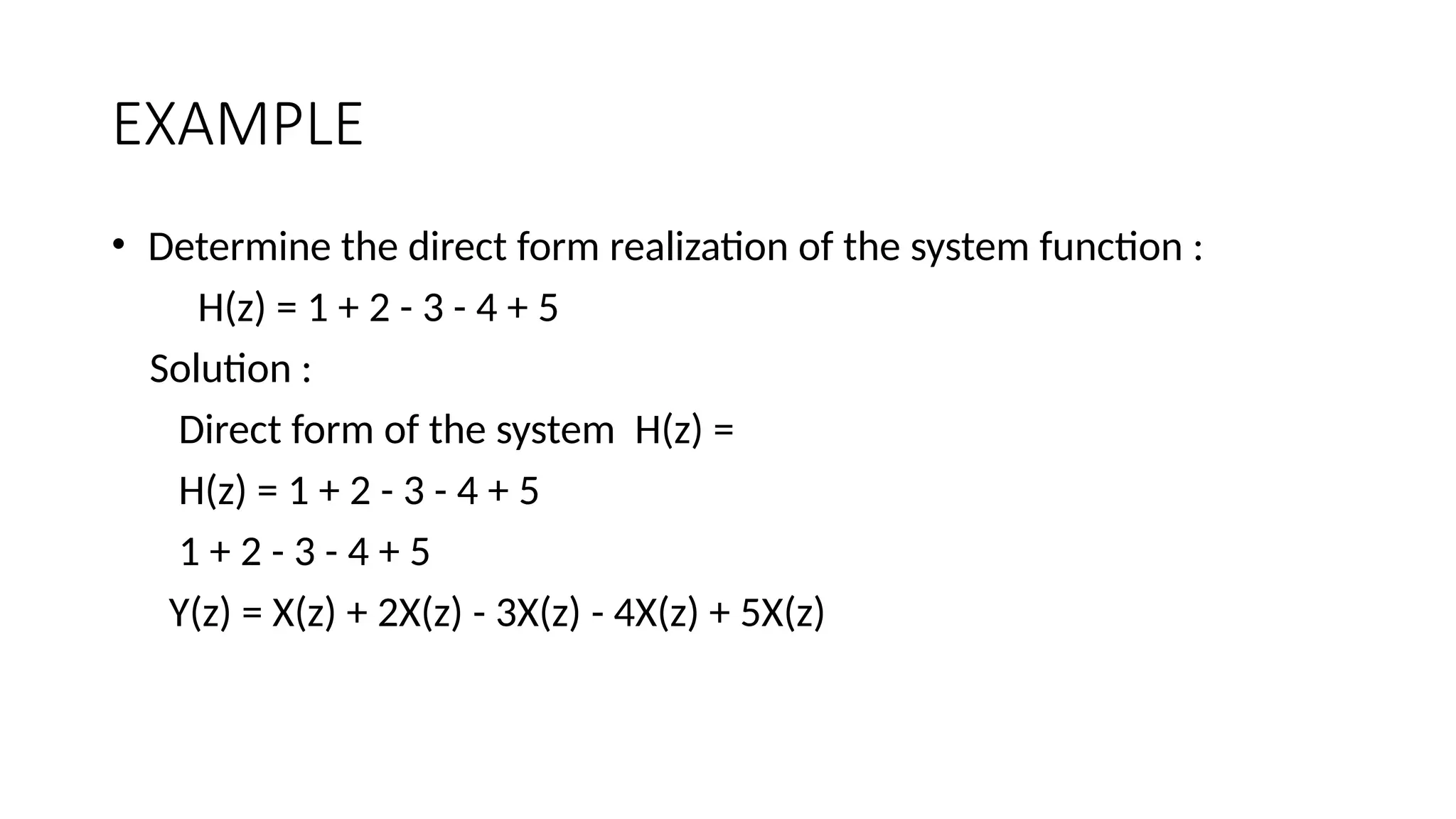
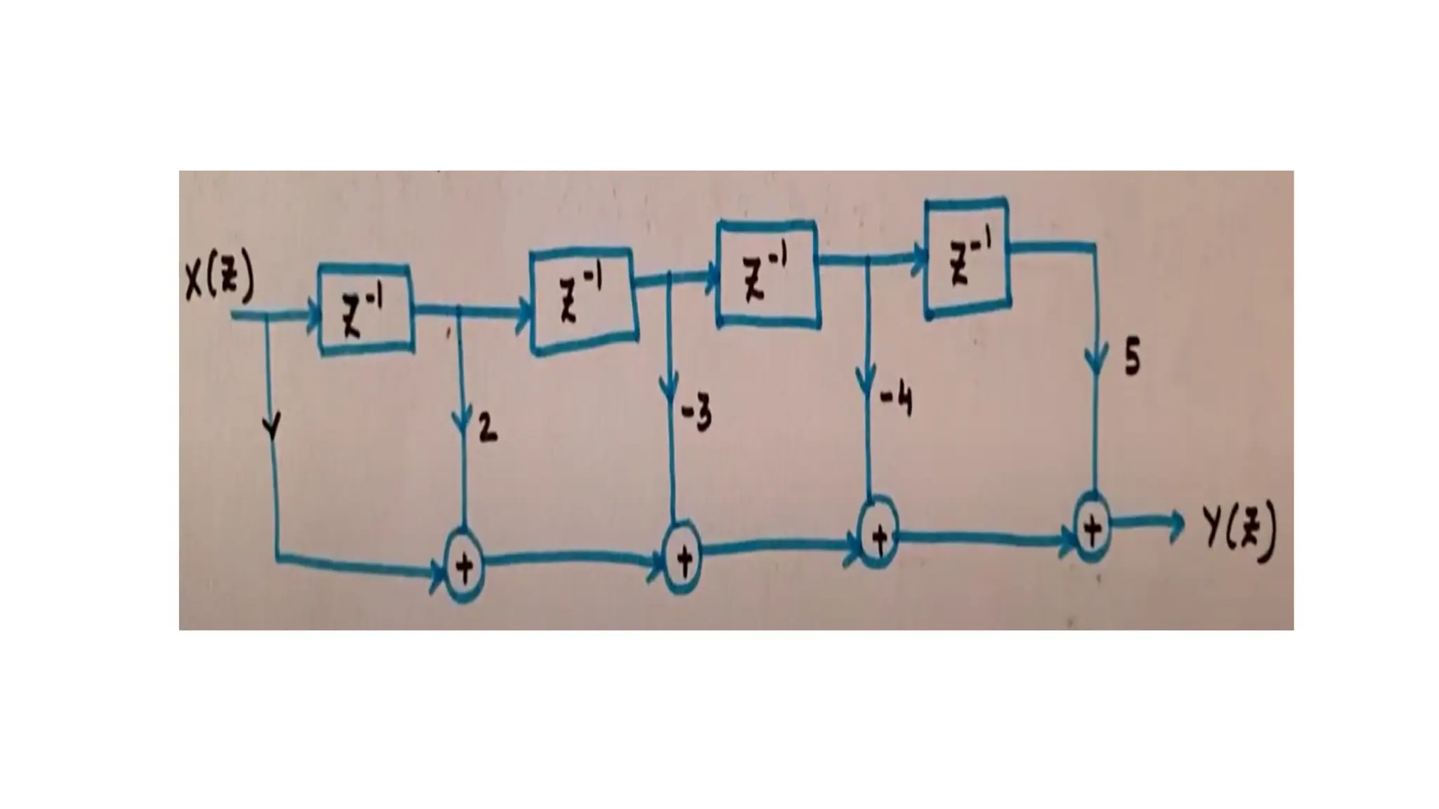
EXAMPLE
• Determine thedirect form realization of the system function :
H(z) = 1 + 2 - 3 - 4 + 5
Solution :
Direct form of the system H(z) =
H(z) = 1 + 2 - 3 - 4 + 5
1 + 2 - 3 - 4 + 5
Y(z) = X(z) + 2X(z) - 3X(z) - 4X(z) + 5X(z)
15.
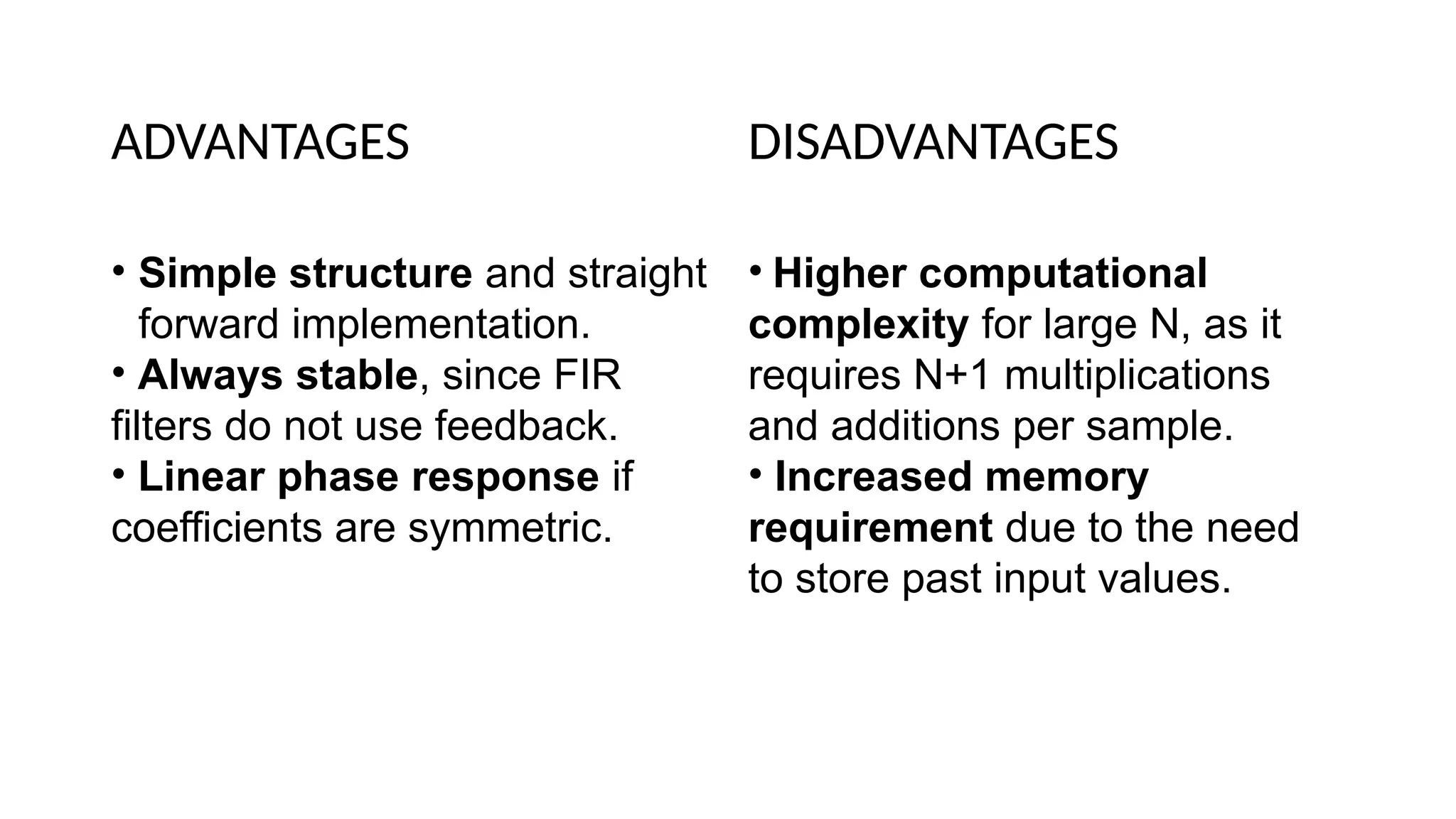
ADVANTAGES
• Simple structureand straight
forward implementation.
• Always stable, since FIR
filters do not use feedback.
• Linear phase response if
coefficients are symmetric.
DISADVANTAGES
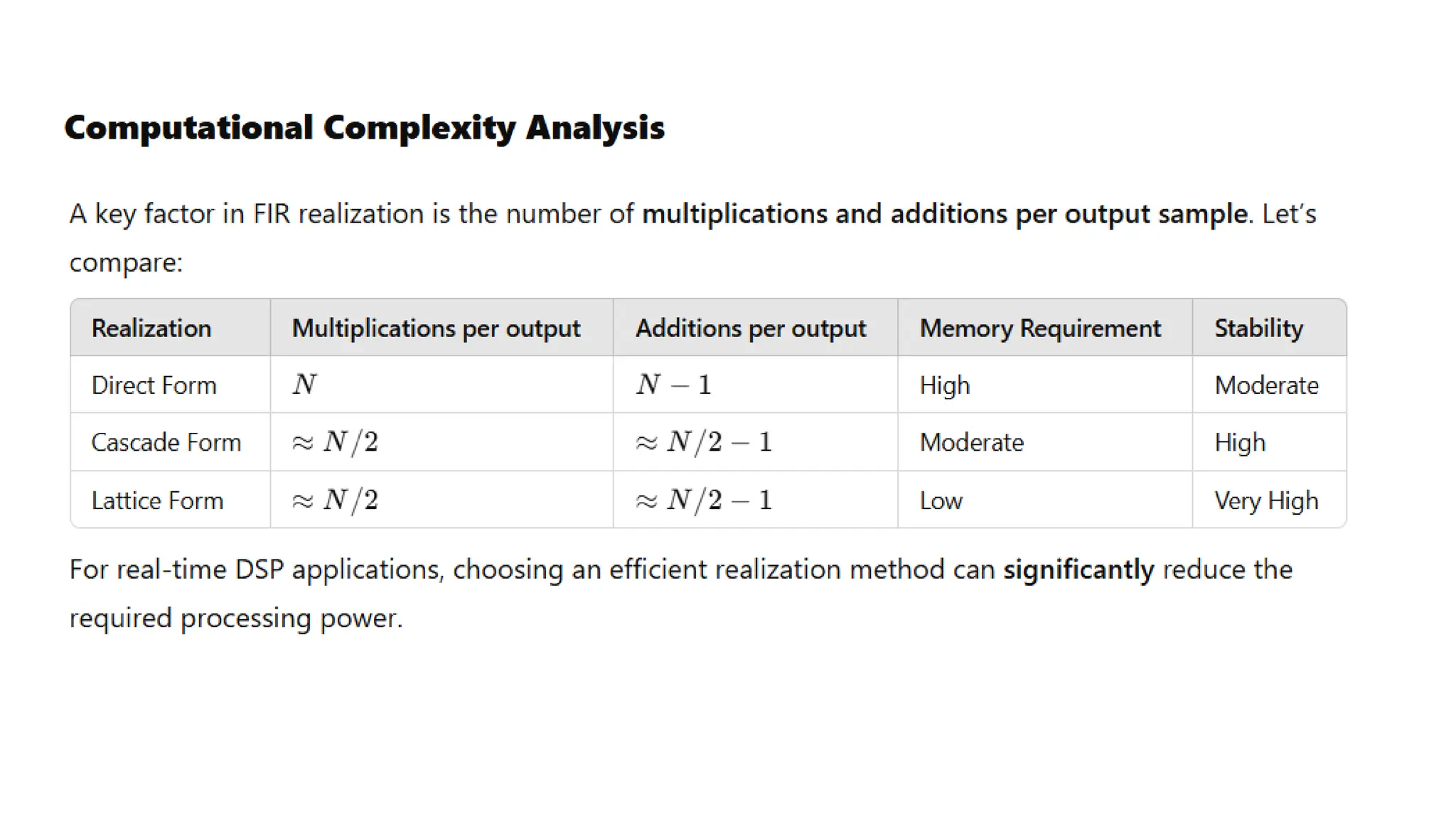
• Higher computational
complexity for large N, as it
requires N+1 multiplications
and additions per sample.
• Increased memory
requirement due to the need
to store past input values.
16.
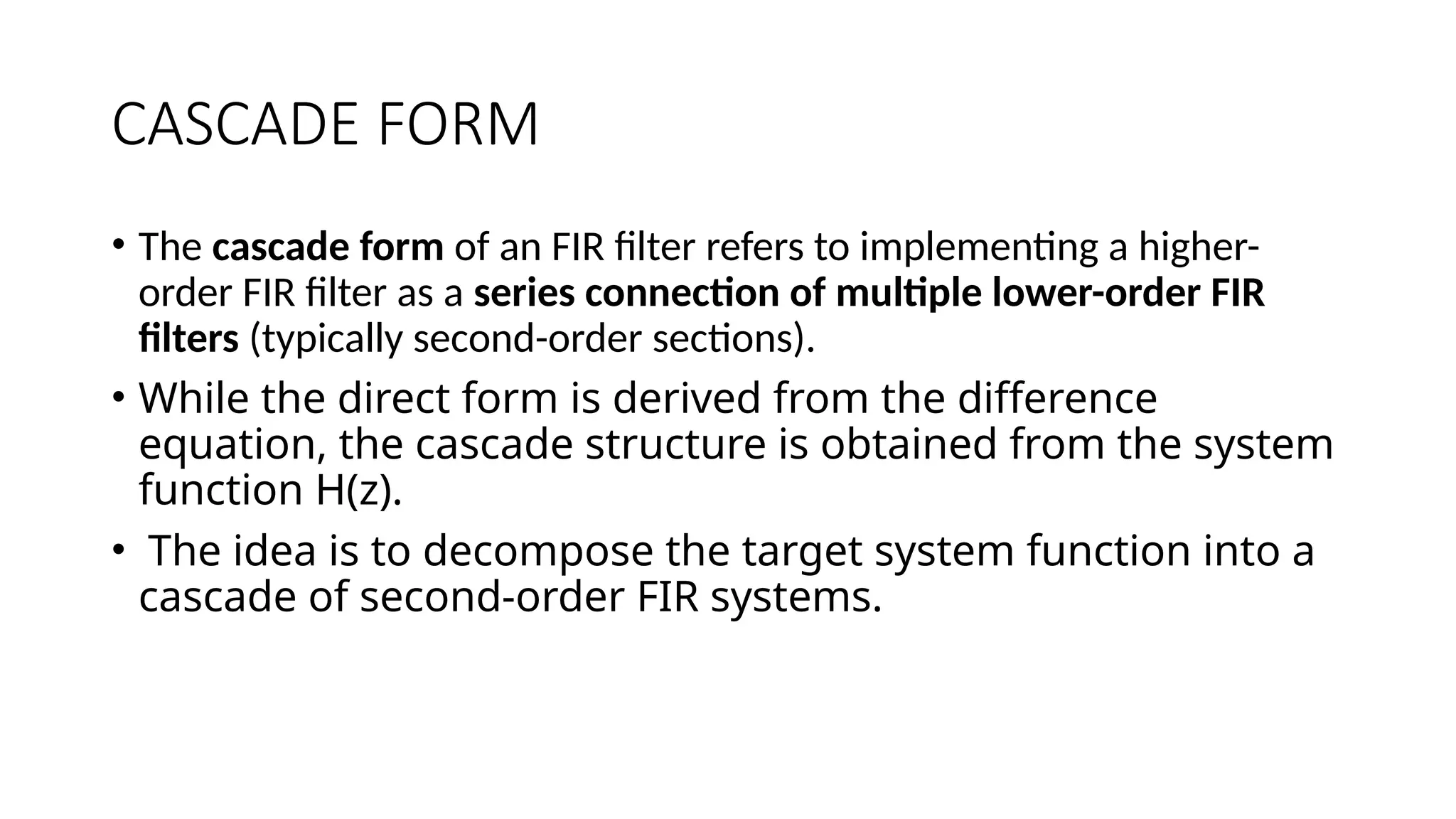
CASCADE FORM
• Thecascade form of an FIR filter refers to implementing a higher-
order FIR filter as a series connection of multiple lower-order FIR
filters (typically second-order sections).
• While the direct form is derived from the difference
equation, the cascade structure is obtained from the system
function H(z).
• The idea is to decompose the target system function into a
cascade of second-order FIR systems.
17.
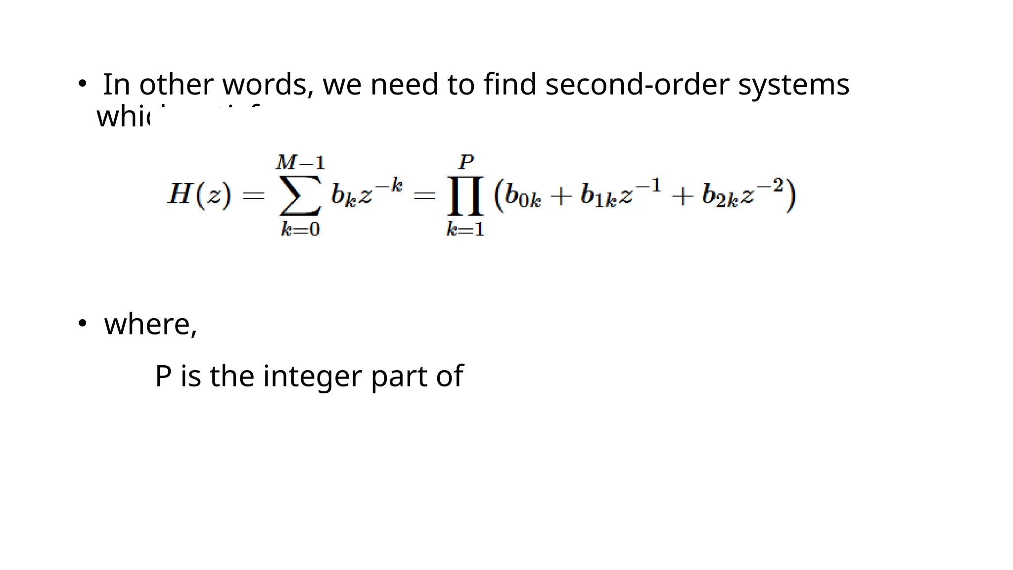
• In otherwords, we need to find second-order systems
which satisfy :
• where,
P is the integer part of
19.
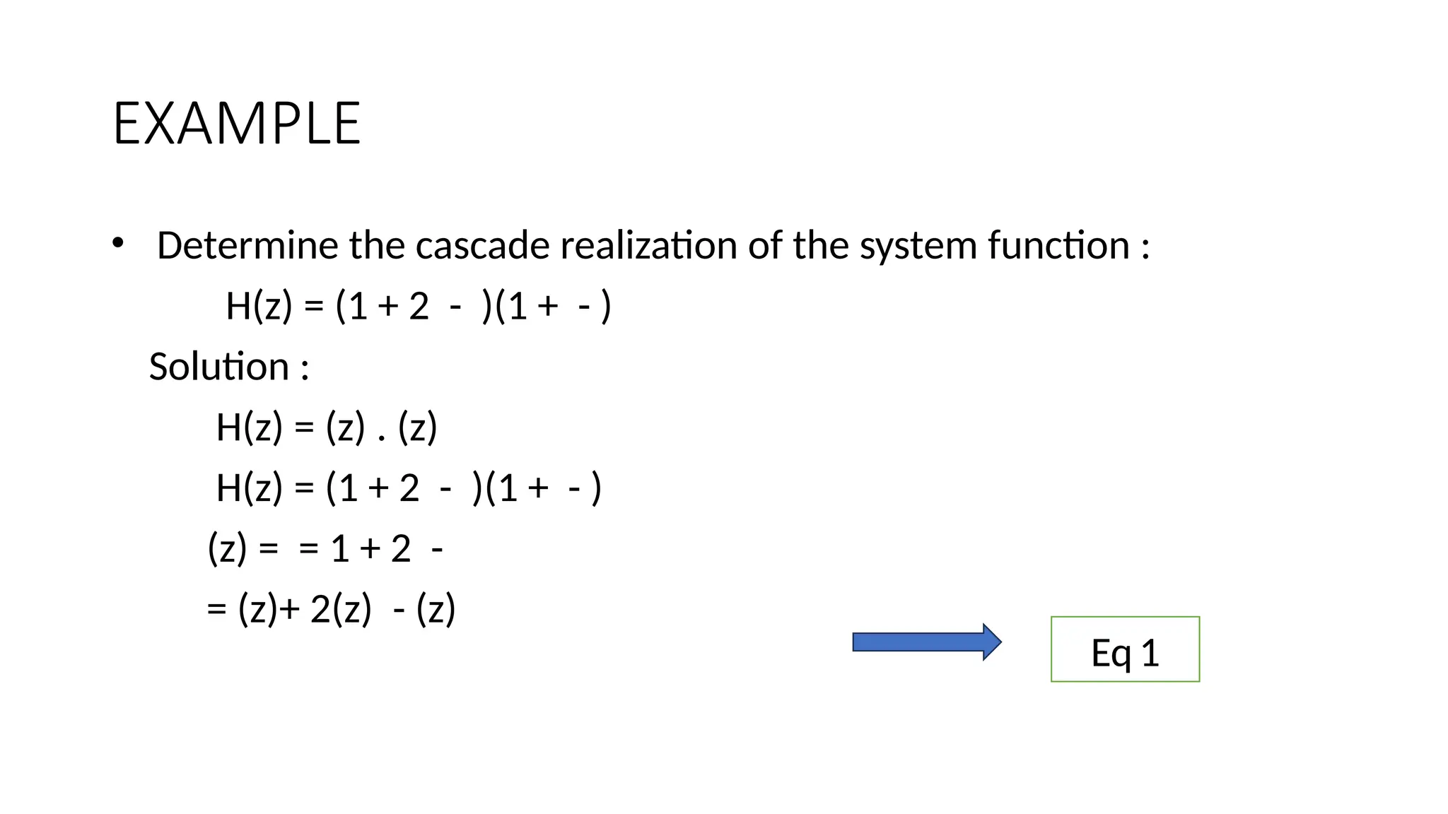
EXAMPLE
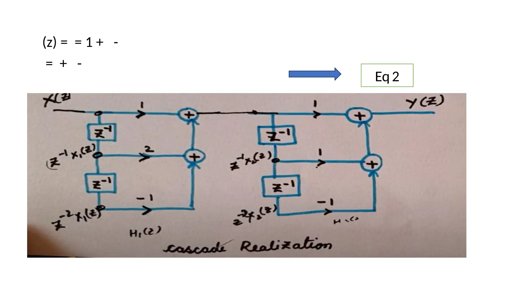
• Determine thecascade realization of the system function :
H(z) = (1 + 2 - )(1 + - )
Solution :
H(z) = (z) . (z)
H(z) = (1 + 2 - )(1 + - )
(z) = = 1 + 2 -
= (z)+ 2(z) - (z)
Eq1
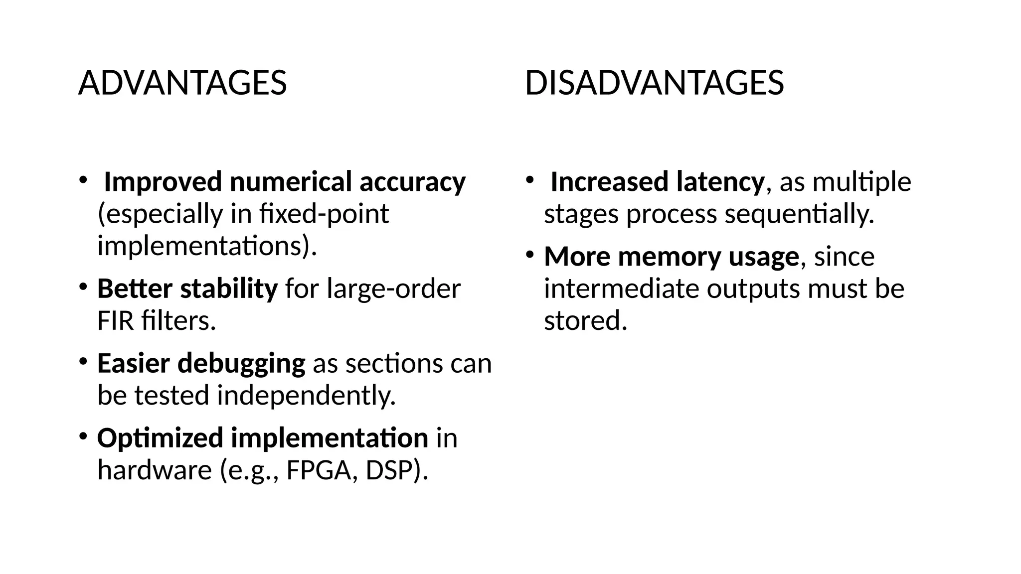
ADVANTAGES
• Improved numericalaccuracy
(especially in fixed-point
implementations).
• Better stability for large-order
FIR filters.
• Easier debugging as sections can
be tested independently.
• Optimized implementation in
hardware (e.g., FPGA, DSP).
DISADVANTAGES
• Increased latency, as multiple
stages process sequentially.
• More memory usage, since
intermediate outputs must be
stored.
2. SPATIAL BEAMFORMING
➔A signal processing technique used in sensor arrays for directional signal
transmission or reception.
➔ Beamforming can be used at both the transmitting and receiving ends in
order to achieve spatial selectivity.
➔ Used for radio or sound waves, in radar, sonar, seismology, wireless
communications, radio astronomy, acoustics and biomedicine.
26.
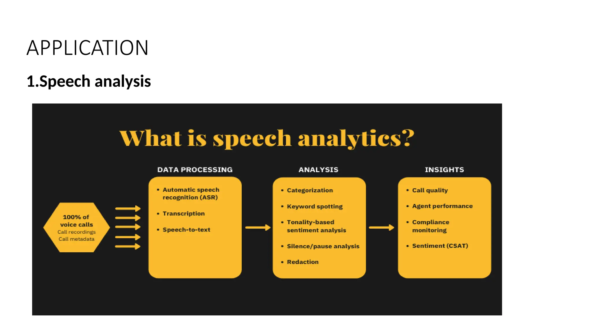
3.Linear predictive Coding
➔It is a method used mostly in audio signal processing and speech
processing for representing the spectral envelope of a digital signal of
speech in compressed form.
➔ Method for encoding good quality speech at a low bit rate and provides
highly accurate estimates of speech parameters.
27.
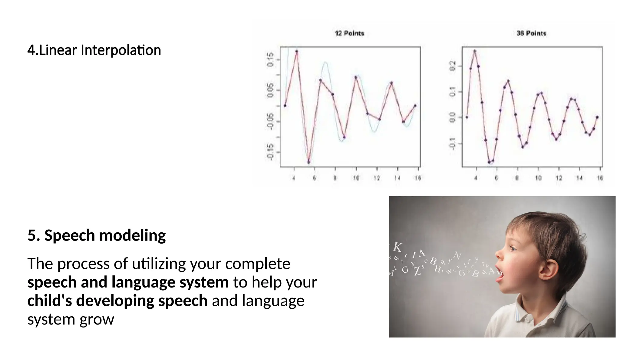
4.Linear Interpolation
5. Speechmodeling
The process of utilizing your complete
speech and language system to help your
child's developing speech and language
system grow
28.
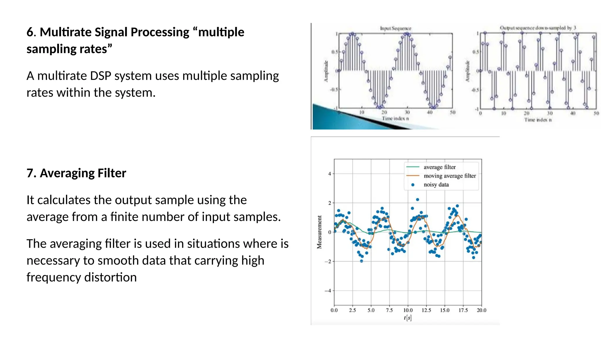
6. Multirate SignalProcessing “multiple
sampling rates”
A multirate DSP system uses multiple sampling
rates within the system.
7. Averaging Filter
It calculates the output sample using the
average from a finite number of input samples.
The averaging filter is used in situations where is
necessary to smooth data that carrying high
frequency distortion
29.
Disadvantages of FIRFilters
● High Order: Requires a higher order for sharp frequency responses.
● More Computations: The computations are more intensive due to many coefficients.
● Memory Usage: More memory is used for storing the coefficients.
● Longer Delay: Longer group delay compared to IIR filters.
● Limited Use: Less efficient in real-time processing that requires speed for efficiency reasons.
![• For an FIR filter of order N, the output y[n] is computed as a
weighted sum of the current and past input samples:
y[n] =
• where:
x[n] is the input signal,
y[n] is the output signal,
h[k] represents the FIR filter coefficients (impulse response),
N is the order of the filter.](https://image.slidesharecdn.com/dspbatch31-250326022614-07480f35/75/Digital-signal-processing-realization-of-FIR-filters-11-2048.jpg)