Downloaded 122 times
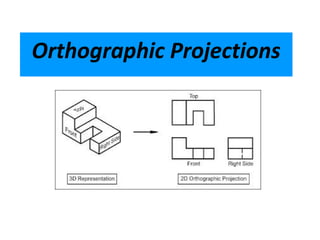
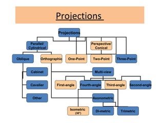
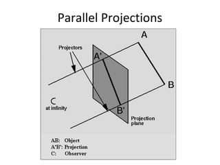
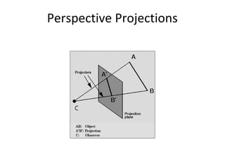
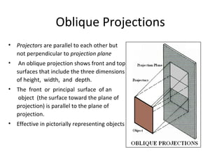
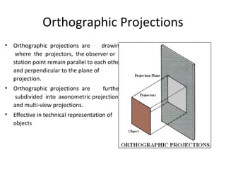
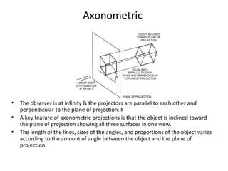
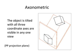
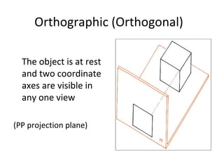
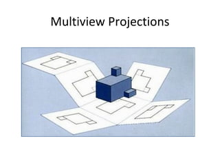

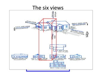
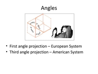
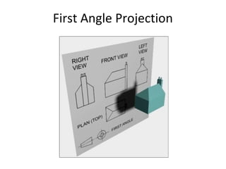
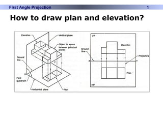
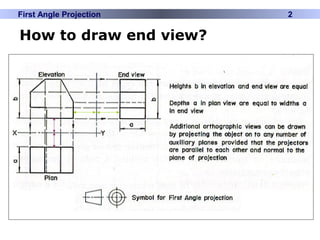
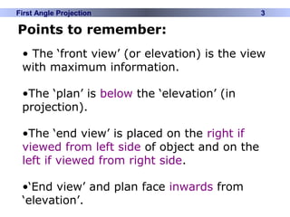
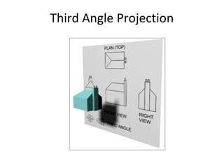
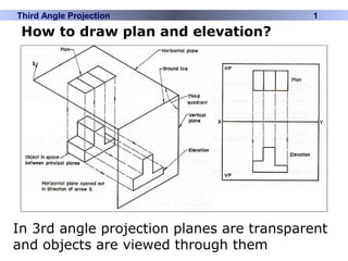

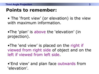


This document discusses different types of technical drawing projections used to represent 3D objects in 2D drawings. It describes orthographic projections where projectors are perpendicular to the projection plane, resulting in front, top, and side views of an object. Axonometric projections show an object inclined toward the projection plane in a single view. Multiview projections use front, top, right side, etc. views. First angle and third angle projections determine the placement of views, with first angle being the European standard and third angle being used in America.