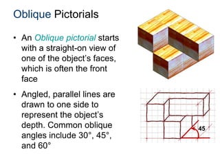
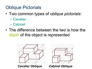
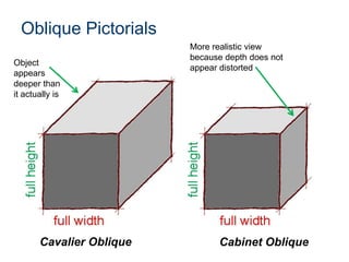
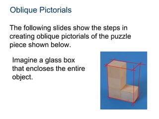
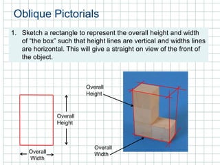
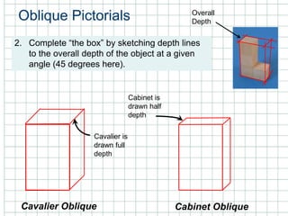
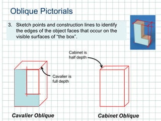
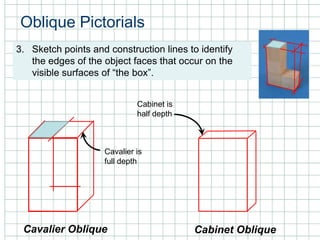
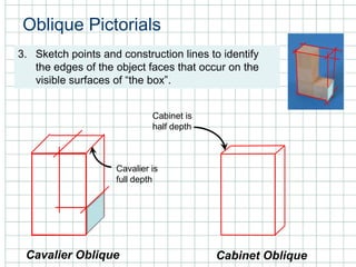
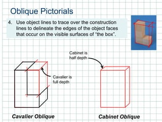
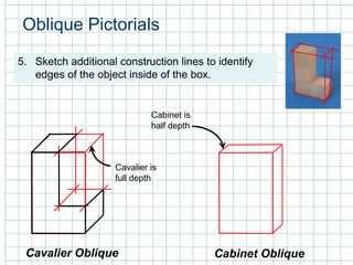
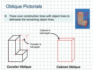
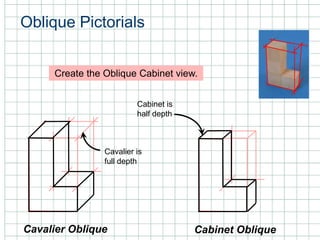
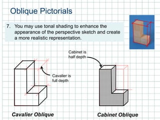
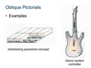
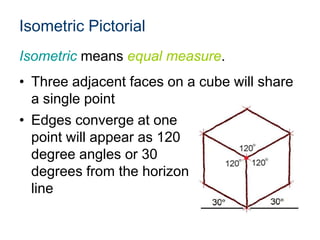
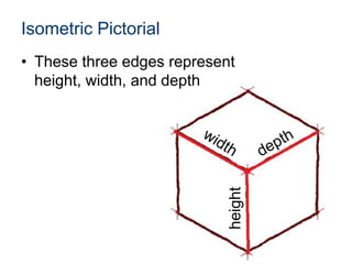
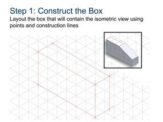
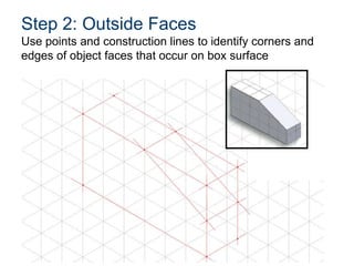
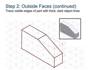
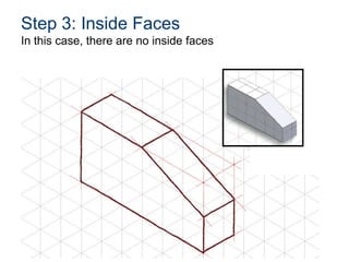
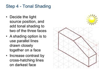
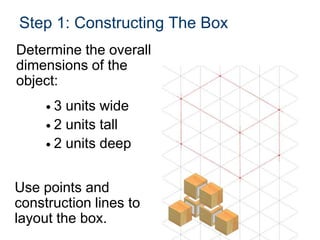
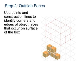
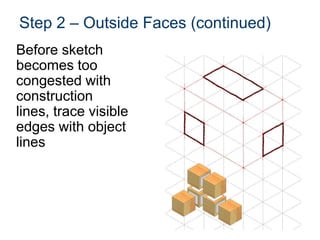
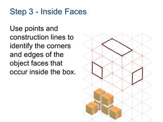
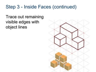
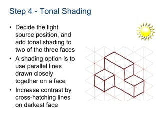
Isometric and Oblique Pictorials
Pictorial Drawing
• 2D illustration of a 3D object
• Shows three faces of an object in one view
• Provides a realistic view of an object
• Three types
Isometric Oblique (Cavalier) PerspectiveOblique (Cabinet)
– Isometric – Oblique – Perspective
Oblique Pictorials
• An Oblique pictorial starts
with a straight-on view of
one of the object’s faces,
which is often the front
face
• Angled, parallel lines are
drawn to one side to
represent the object’s
depth. Common oblique
angles include 30°, 45°,
and 60°
45
Oblique Pictorials
• Two common types of oblique pictorials:
– Cavalier
– Cabinet
• The difference between the two is how the
depth of the object is represented
Cavalier Oblique Cabinet Oblique
Oblique Pictorials
Cavalier Oblique Cabinet Oblique
Object
appears
deeper than
it actually is
More realistic view
because depth does not
appear distorted
The following slides show the steps in
creating oblique pictorials of the puzzle
piece shown below.
Oblique Pictorials
Imagine a glass box
that encloses the entire
object.
Oblique Pictorials
1. Sketch a rectangle to represent the overall height and width
of “the box” such that height lines are vertical and widths lines
are horizontal. This will give a straight on view of the front of
the object.
Overall
Height
Overall
WidthOverall
Width
Overall
Height
Oblique Pictorials
2. Complete “the box” by sketching depth lines
to the overall depth of the object at a given
angle (45 degrees here).
Cavalier Oblique Cabinet Oblique
Cavalier is
drawn full
depth
Cabinet is
drawn half
depth
Overall
Depth
Oblique Pictorials
3. Sketch points and construction lines to identify
the edges of the object faces that occur on the
visible surfaces of “the box”.
Cavalier Oblique Cabinet Oblique
Cavalier is
full depth
Cabinet is
half depth
Oblique Pictorials
3. Sketch points and construction lines to identify
the edges of the object faces that occur on the
visible surfaces of “the box”.
Cavalier Oblique Cabinet Oblique
Cavalier is
full depth
Cabinet is
half depth
Oblique Pictorials
3. Sketch points and construction lines to identify
the edges of the object faces that occur on the
visible surfaces of “the box”.
Cavalier Oblique Cabinet Oblique
Cavalier is
full depth
Cabinet is
half depth
Oblique Pictorials
4. Use object lines to trace over the construction
lines to delineate the edges of the object faces
that occur on the visible surfaces of “the box”.
Cavalier Oblique Cabinet Oblique
Cavalier is
full depth
Cabinet is
half depth
Oblique Pictorials
5. Sketch additional construction lines to identify
edges of the object inside of the box.
Cavalier Oblique Cabinet Oblique
Cavalier is
full depth
Cabinet is
half depth
Oblique Pictorials
6. Trace over construction lines with object lines to
delineate the remaining object lines.
Cavalier Oblique Cabinet Oblique
Cavalier is
full depth
Cabinet is
half depth
Oblique Pictorials
Cavalier Oblique Cabinet Oblique
Cavalier is
full depth
Cabinet is
half depth
Create the Oblique Cabinet view.
Oblique Pictorials
Cavalier Oblique Cabinet Oblique
Cavalier is
full depth
Cabinet is
half depth
7. You may use tonal shading to enhance the
appearance of the perspective sketch and create
a more realistic representation.
Oblique Pictorials
• Examples
Interlocking pavement concept
Game system
controller
Isometric Pictorial
Isometric means equal measure.
• Three adjacent faces on a cube will share
a single point
• Edges converge at one
point will appear as 120
degree angles or 30
degrees from the horizon
line
Isometric Pictorial
• These three edges represent
height, width, and depth
height
View labels
Top, Front, Right Side
view orientation
Top, Left Side, Front,
view orientation
View Selection
• Recommendations for how to select the
front view
– Most natural position or use
– Shows best shape and characteristic contours
– Longest dimensions
– Fewest hidden lines
– Most stable and natural position
Orthographic View Selection
Best shape
Description
Longest Dimension
Most natural position
No hidden edges
The Box Method
• The box method is a
sketching technique
used to maintain
proportionality
• It starts with a
sketcher envisioning
an object contained
within an imaginary
box
Proportion and Estimation
• Good sketching
requires a sense of
proportion, and the
ability to estimate
size, distance, angles,
and other spatial
relationships
Isometric Sketching
• The following
examples show
steps used to
create isometric
sketches of simple
geometric
objects, including
tonal shading
techniques
EXAMPLE 1
Isometric Sketch
Step 1: Construct the Box
Layout the box that will contain the isometric view using
points and construction lines
Step 2: Outside Faces
Use points and construction lines to identify corners and
edges of object faces that occur on box surface
Step 2: Outside Faces (continued)
Trace visible edges of part with thick, dark object lines
Step 3: Inside Faces
In this case, there are no inside faces
Step 4 - Tonal Shading
• Decide the light
source position, and
add tonal shading to
two of the three faces
• A shading option is to
use parallel lines
drawn closely
together on a face
• Increase contrast by
cross-hatching lines
on darkest face
EXAMPLE 2
Isometric Sketch
Step 1: Constructing The Box
• 3 units wide
• 2 units tall
• 2 units deep
Determine the overall
dimensions of the
object:
Use points and
construction lines to
layout the box.
Step 2: Outside Faces
Use points and
construction lines to
identify corners and
edges of object faces
that occur on surface
of the box
Step 2 – Outside Faces (continued)
Before sketch
becomes too
congested with
construction
lines, trace visible
edges with object
lines
Step 3 - Inside Faces
Use points and
construction lines to
identify the corners
and edges of the
object faces that
occur inside the box.
Step 3 - Inside Faces (continued)
Trace out remaining
visible edges with
object lines
Step 4 - Tonal Shading
• Decide the light
source position, and
add tonal shading to
two of the three faces
• A shading option is to
use parallel lines
drawn closely
together on a face
• Increase contrast by
cross-hatching lines
on darkest face
Isometric Sketch Example
Isometric Sketch
Historical Example
• Earl Silas Tupper
(1907 -1983)
invented an air-
tight Tupper Seal
in 1947
• Patent drawings of
bowl and cover,
1957 (isometric
pictorial)
Courtesy Smithsonian Institute:
http://sil.si.edu/exhibitions/doodles
References
Tupper, Earl Silas. Patent drawings, 1957. Smithsonian
Institute: http://sil.si.edu.exhibitions/doodles
Wikipedia (2011). Three point flexural test. Retrieved from
http://en.wikipedia.org/wiki/File:Threepoint.jpg

2.1.a isometric obliquepictorials

  • 1.
  • 2.
    Pictorial Drawing • 2Dillustration of a 3D object • Shows three faces of an object in one view • Provides a realistic view of an object • Three types Isometric Oblique (Cavalier) PerspectiveOblique (Cabinet) – Isometric – Oblique – Perspective
  • 3.
    Oblique Pictorials • AnOblique pictorial starts with a straight-on view of one of the object’s faces, which is often the front face • Angled, parallel lines are drawn to one side to represent the object’s depth. Common oblique angles include 30°, 45°, and 60° 45
  • 4.
    Oblique Pictorials • Twocommon types of oblique pictorials: – Cavalier – Cabinet • The difference between the two is how the depth of the object is represented Cavalier Oblique Cabinet Oblique
  • 5.
    Oblique Pictorials Cavalier ObliqueCabinet Oblique Object appears deeper than it actually is More realistic view because depth does not appear distorted
  • 6.
    The following slidesshow the steps in creating oblique pictorials of the puzzle piece shown below. Oblique Pictorials Imagine a glass box that encloses the entire object.
  • 7.
    Oblique Pictorials 1. Sketcha rectangle to represent the overall height and width of “the box” such that height lines are vertical and widths lines are horizontal. This will give a straight on view of the front of the object. Overall Height Overall WidthOverall Width Overall Height
  • 8.
    Oblique Pictorials 2. Complete“the box” by sketching depth lines to the overall depth of the object at a given angle (45 degrees here). Cavalier Oblique Cabinet Oblique Cavalier is drawn full depth Cabinet is drawn half depth Overall Depth
  • 9.
    Oblique Pictorials 3. Sketchpoints and construction lines to identify the edges of the object faces that occur on the visible surfaces of “the box”. Cavalier Oblique Cabinet Oblique Cavalier is full depth Cabinet is half depth
  • 10.
    Oblique Pictorials 3. Sketchpoints and construction lines to identify the edges of the object faces that occur on the visible surfaces of “the box”. Cavalier Oblique Cabinet Oblique Cavalier is full depth Cabinet is half depth
  • 11.
    Oblique Pictorials 3. Sketchpoints and construction lines to identify the edges of the object faces that occur on the visible surfaces of “the box”. Cavalier Oblique Cabinet Oblique Cavalier is full depth Cabinet is half depth
  • 12.
    Oblique Pictorials 4. Useobject lines to trace over the construction lines to delineate the edges of the object faces that occur on the visible surfaces of “the box”. Cavalier Oblique Cabinet Oblique Cavalier is full depth Cabinet is half depth
  • 13.
    Oblique Pictorials 5. Sketchadditional construction lines to identify edges of the object inside of the box. Cavalier Oblique Cabinet Oblique Cavalier is full depth Cabinet is half depth
  • 14.
    Oblique Pictorials 6. Traceover construction lines with object lines to delineate the remaining object lines. Cavalier Oblique Cabinet Oblique Cavalier is full depth Cabinet is half depth
  • 15.
    Oblique Pictorials Cavalier ObliqueCabinet Oblique Cavalier is full depth Cabinet is half depth Create the Oblique Cabinet view.
  • 16.
    Oblique Pictorials Cavalier ObliqueCabinet Oblique Cavalier is full depth Cabinet is half depth 7. You may use tonal shading to enhance the appearance of the perspective sketch and create a more realistic representation.
  • 17.
    Oblique Pictorials • Examples Interlockingpavement concept Game system controller
  • 18.
    Isometric Pictorial Isometric meansequal measure. • Three adjacent faces on a cube will share a single point • Edges converge at one point will appear as 120 degree angles or 30 degrees from the horizon line
  • 19.
    Isometric Pictorial • Thesethree edges represent height, width, and depth height
  • 20.
    View labels Top, Front,Right Side view orientation Top, Left Side, Front, view orientation
  • 21.
    View Selection • Recommendationsfor how to select the front view – Most natural position or use – Shows best shape and characteristic contours – Longest dimensions – Fewest hidden lines – Most stable and natural position
  • 22.
    Orthographic View Selection Bestshape Description Longest Dimension Most natural position No hidden edges
  • 23.
    The Box Method •The box method is a sketching technique used to maintain proportionality • It starts with a sketcher envisioning an object contained within an imaginary box
  • 24.
    Proportion and Estimation •Good sketching requires a sense of proportion, and the ability to estimate size, distance, angles, and other spatial relationships
  • 25.
    Isometric Sketching • Thefollowing examples show steps used to create isometric sketches of simple geometric objects, including tonal shading techniques
  • 26.
  • 27.
    Step 1: Constructthe Box Layout the box that will contain the isometric view using points and construction lines
  • 28.
    Step 2: OutsideFaces Use points and construction lines to identify corners and edges of object faces that occur on box surface
  • 29.
    Step 2: OutsideFaces (continued) Trace visible edges of part with thick, dark object lines
  • 30.
    Step 3: InsideFaces In this case, there are no inside faces
  • 31.
    Step 4 -Tonal Shading • Decide the light source position, and add tonal shading to two of the three faces • A shading option is to use parallel lines drawn closely together on a face • Increase contrast by cross-hatching lines on darkest face
  • 32.
  • 33.
    Step 1: ConstructingThe Box • 3 units wide • 2 units tall • 2 units deep Determine the overall dimensions of the object: Use points and construction lines to layout the box.
  • 34.
    Step 2: OutsideFaces Use points and construction lines to identify corners and edges of object faces that occur on surface of the box
  • 35.
    Step 2 –Outside Faces (continued) Before sketch becomes too congested with construction lines, trace visible edges with object lines
  • 36.
    Step 3 -Inside Faces Use points and construction lines to identify the corners and edges of the object faces that occur inside the box.
  • 37.
    Step 3 -Inside Faces (continued) Trace out remaining visible edges with object lines
  • 38.
    Step 4 -Tonal Shading • Decide the light source position, and add tonal shading to two of the three faces • A shading option is to use parallel lines drawn closely together on a face • Increase contrast by cross-hatching lines on darkest face
  • 39.
  • 40.
  • 41.
    Isometric Sketch Historical Example •Earl Silas Tupper (1907 -1983) invented an air- tight Tupper Seal in 1947 • Patent drawings of bowl and cover, 1957 (isometric pictorial) Courtesy Smithsonian Institute: http://sil.si.edu/exhibitions/doodles
  • 42.
    References Tupper, Earl Silas.Patent drawings, 1957. Smithsonian Institute: http://sil.si.edu.exhibitions/doodles Wikipedia (2011). Three point flexural test. Retrieved from http://en.wikipedia.org/wiki/File:Threepoint.jpg

Editor's Notes

  • #4 You may choose to use an oblique representation for design ideas in IED. And, you should be able to identify the two different oblique views – cavalier and cabinet.
  • #6 A cavalier oblique [click] represents the object with full depth [click]. This tends to create the illusion that the object is deeper than it actually is. [click]A cabinet oblique [click] represents the object with half depth [click]. The cabinet oblique, although actually drawn to half depth provides a more realistic view. [click]
  • #9 For the same object, the “front” (straight on) face is drawn the same for the cavalier and the cabinet oblique views.For a cavalier oblique, the depth of the object is drawn to full scale. For the cabinet oblique, the depth is drawn to a length of half of the actual depth measurement.
  • #10 [Note the shading on the photographic image that is replicated in the sketch.]
  • #11 [Note the shading on the photographic image that is replicated in the sketch.]
  • #12 [Note the shading on the photographic image that is replicated in the sketch.]
  • #16 Now, you create the cabinet oblique sketch of the puzzle piece.
  • #21 Isometric views can be presented in two different view orientations. We will use the Top, Front, Right Side view orientation exclusively in IED.
  • #28 Stress the importance of light construction lines when constructing the box and connecting the points.
  • #32 Tonal shading is a technique that helps enhance the sketch and create a more realistic representation. It imitates reflections and shadows that would naturally occur when a direct light source is introduced.
  • #39 Again, tonal shading is a technique that helps enhance the sketch and create a more realistic representation. It imitates reflections and shadows that would naturally occur when a direct light source is introduced.