Download to read offline
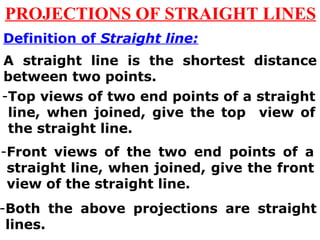
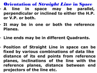
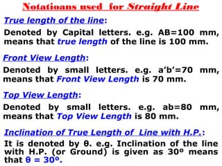
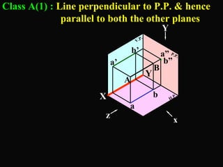
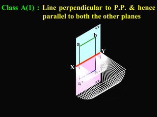
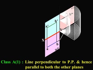
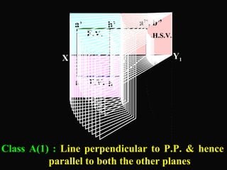
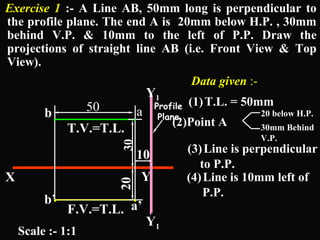
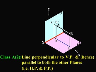
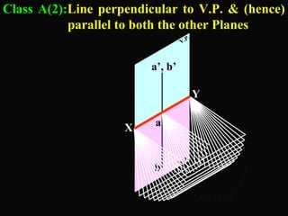
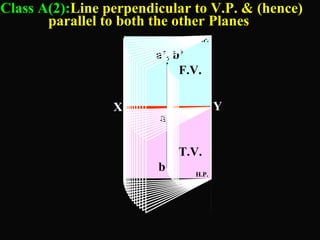
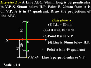
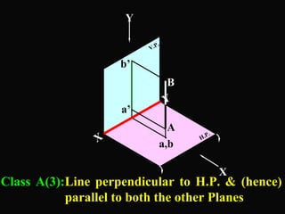
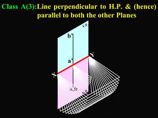
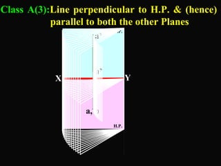
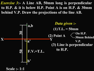
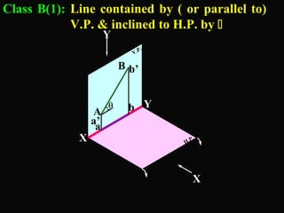
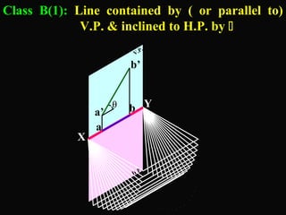
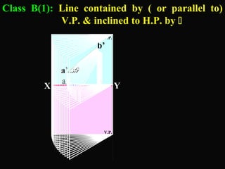
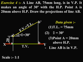
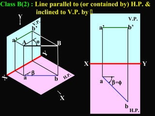
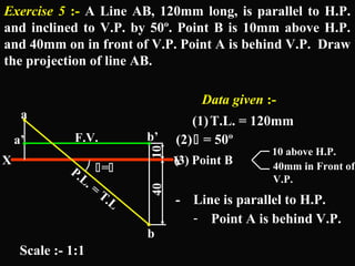
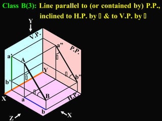
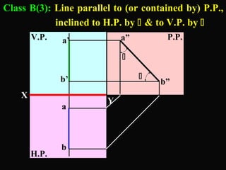
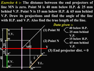
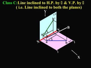
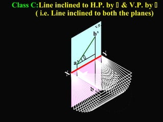
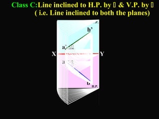
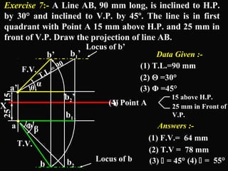
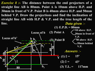
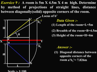
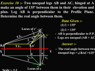
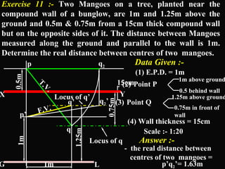
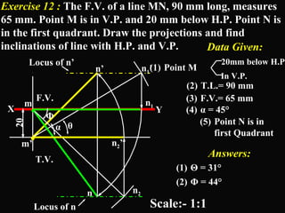
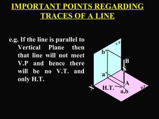
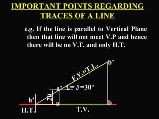
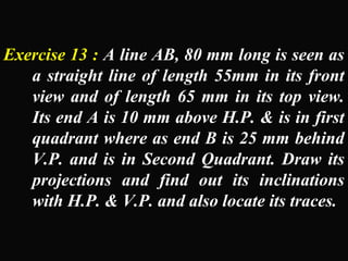
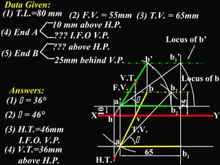
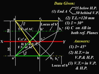

The document discusses projections of straight lines. It defines a straight line and explains that the top and front views of a straight line are also straight lines. It describes different positions a line may have with respect to the horizontal and vertical planes, such as perpendicular, parallel or inclined. Notations used for dimensions of the line are also defined, such as true length, front view length, and inclinations. Different classes of line positions are described, including lines perpendicular or parallel to reference planes or inclined to multiple planes. Examples are given to demonstrate how to draw projections of lines in different positions.