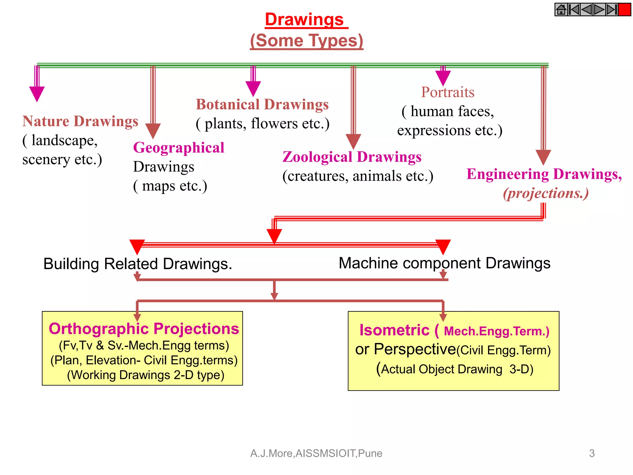
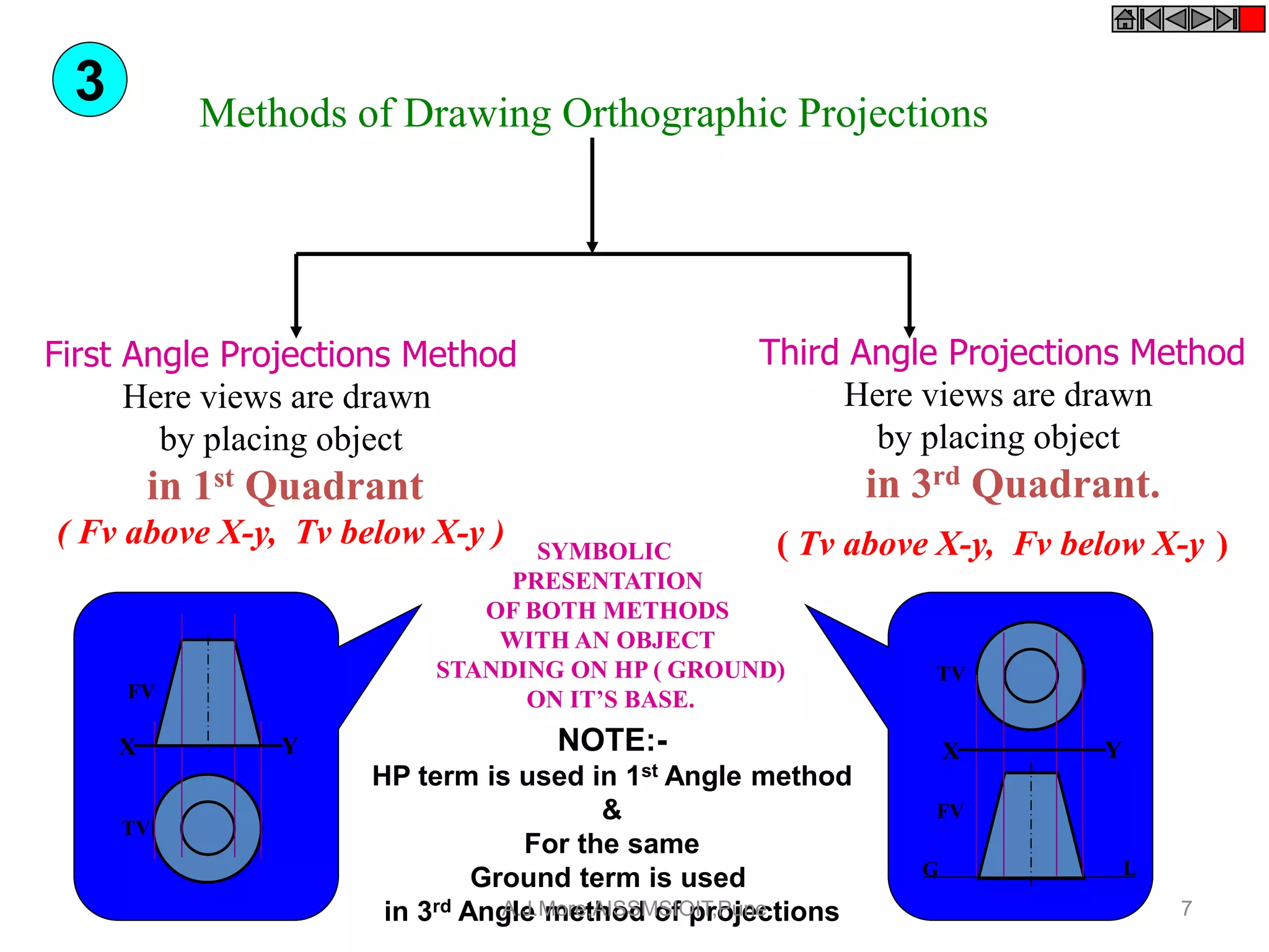
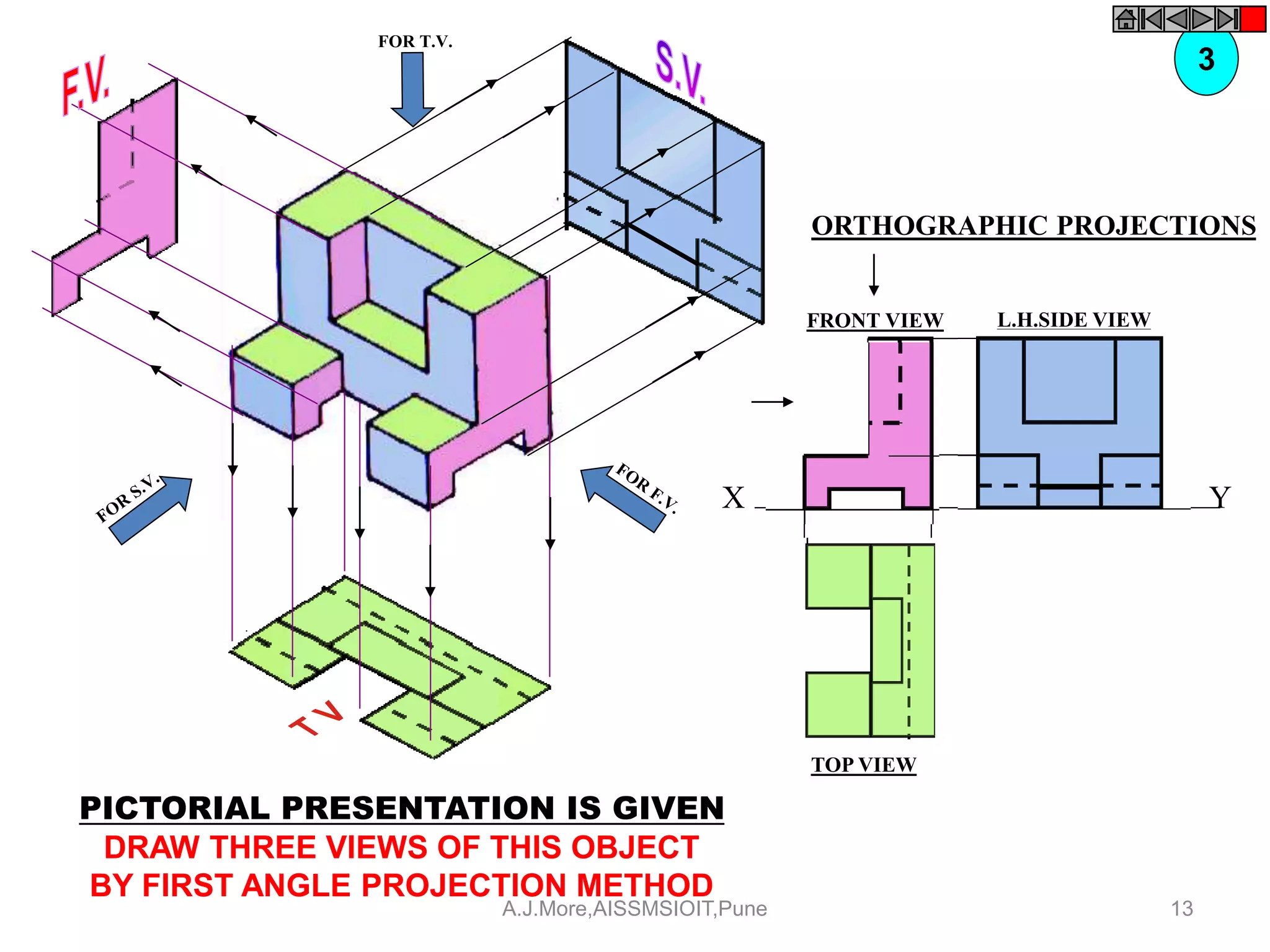
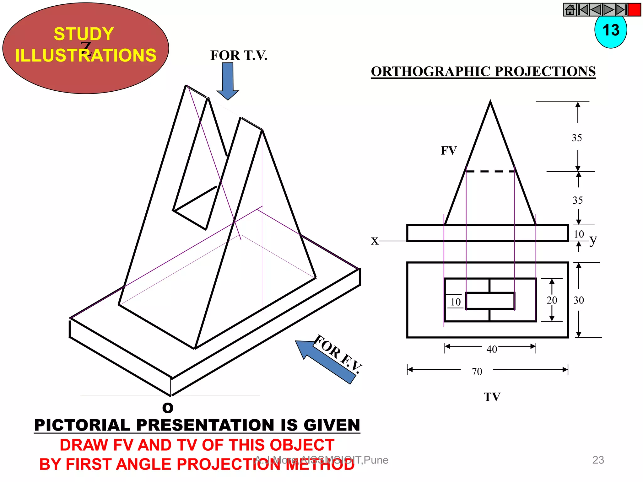
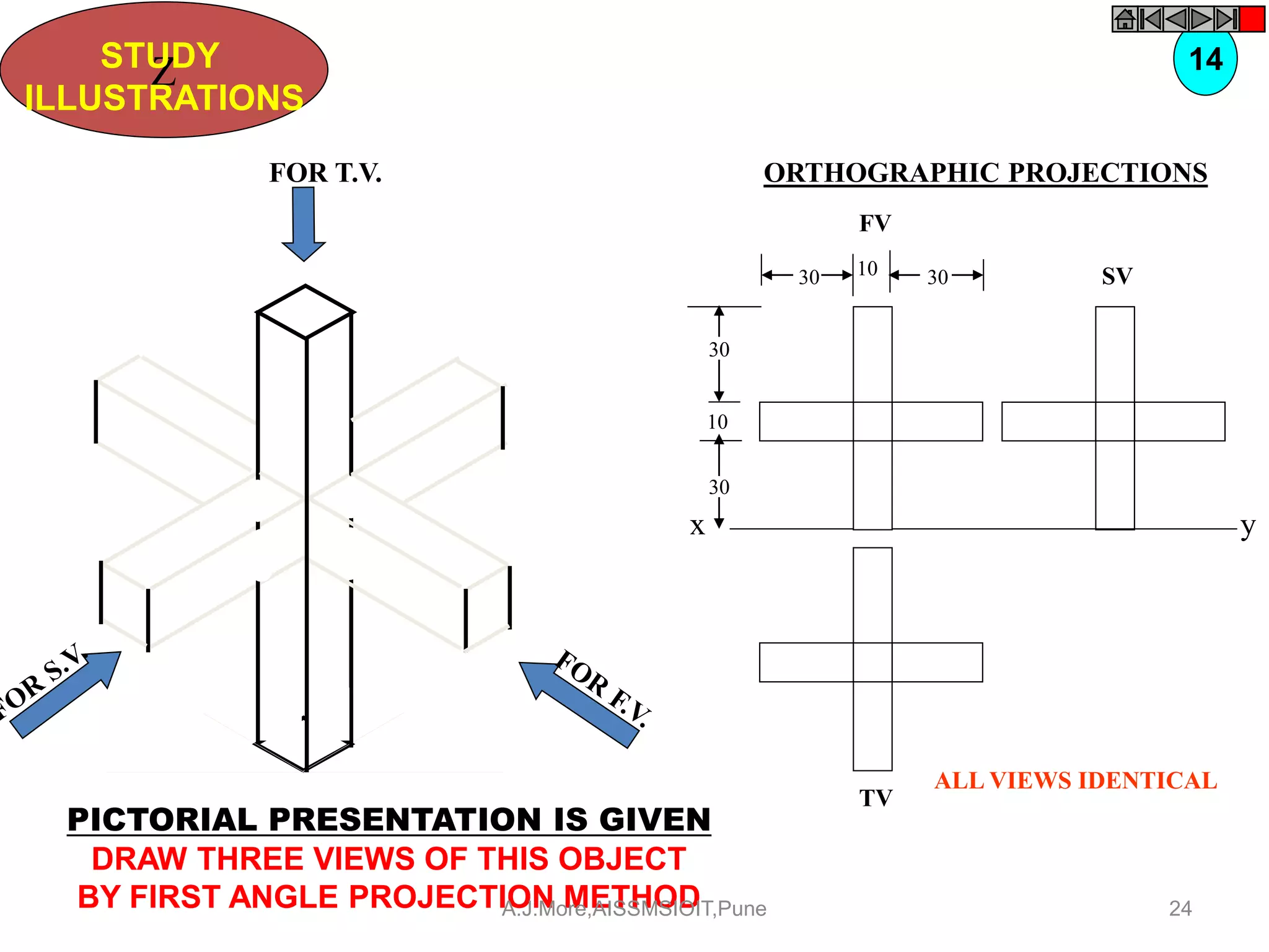
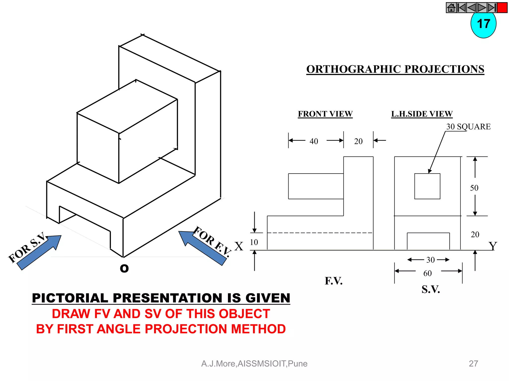
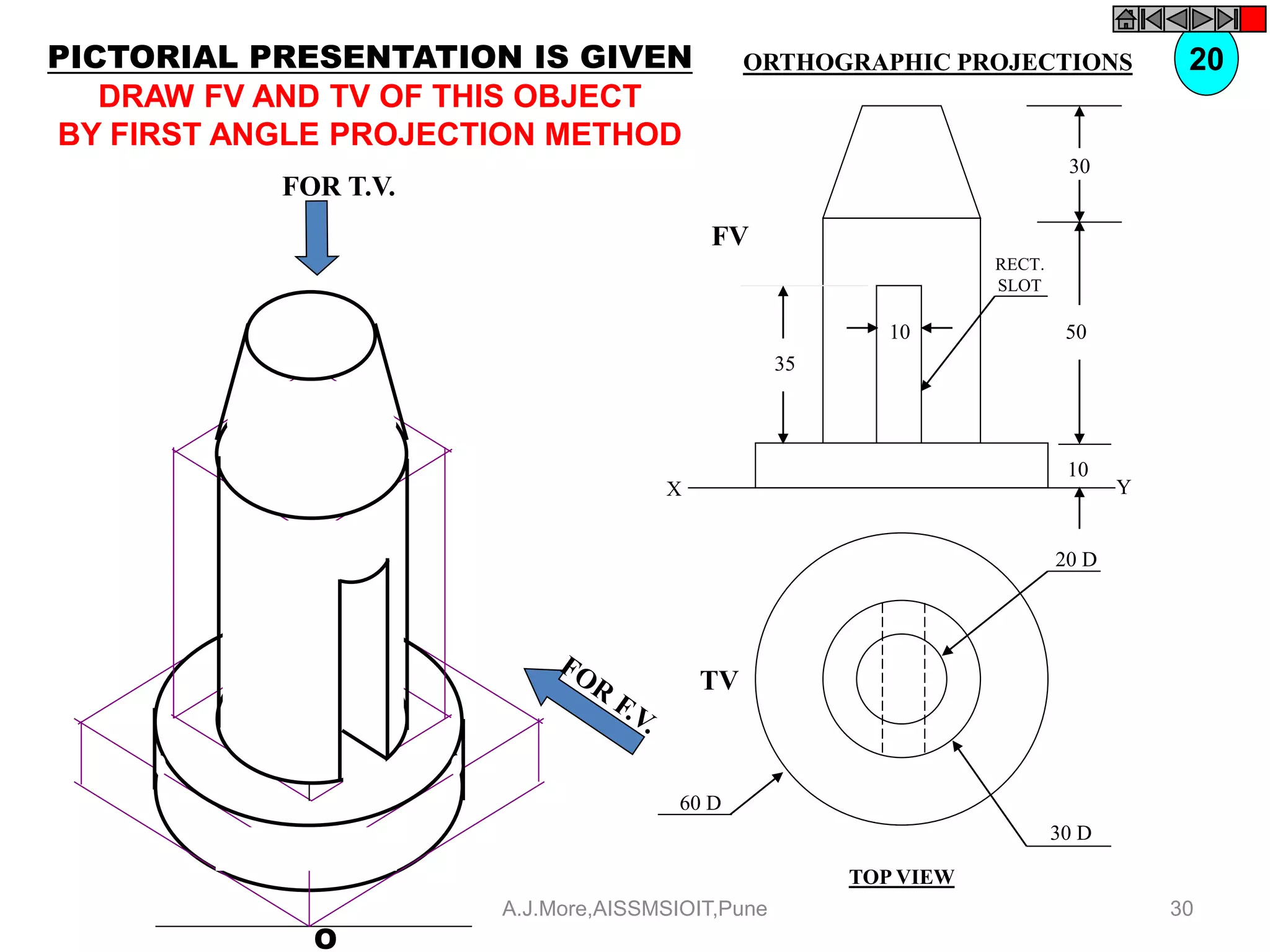
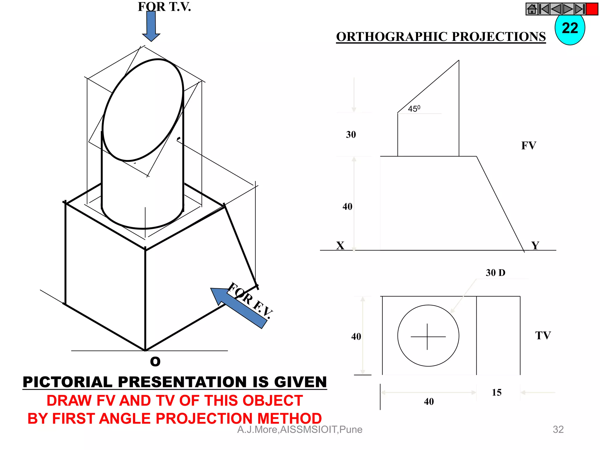
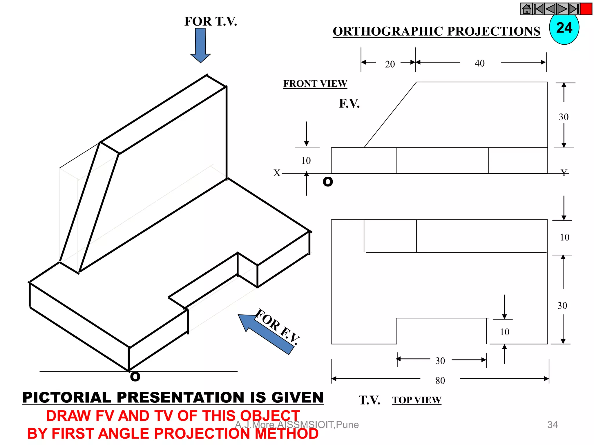
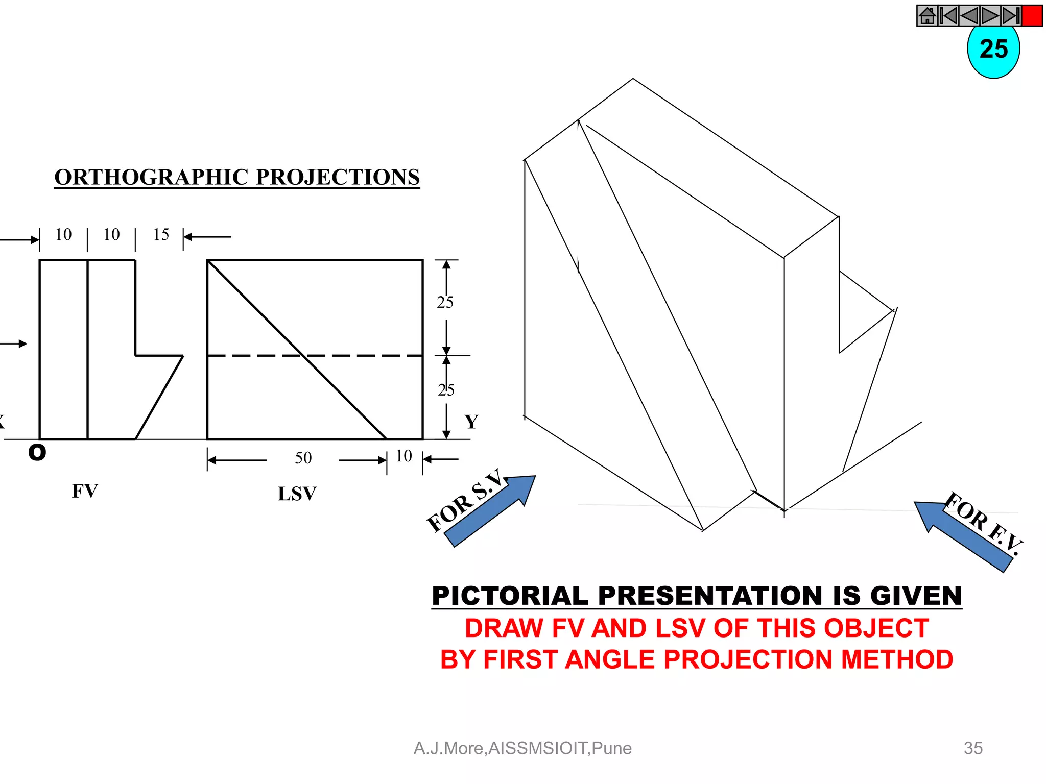
This document discusses orthographic projections and technical drawings. It provides examples of different types of drawings and defines key terms related to orthographic projections. Specifically, it explains that orthographic projections involve projecting different views of an object onto planes that are perpendicular to the object. The front view is projected onto the vertical plane, the top view onto the horizontal plane, and the side view onto the profile plane. It also describes the first angle and third angle methods of projection.
introduction of engineering graphics ,projection of points,lines,planes,solids,section of solids,development of surfaces,isometric projection,perspective projection
For those students who start there career in technical line like ITI, Diploma, Engineering of any field this ppt is helpful for them to understand the Engineering Drawing and Its Basic concepts of Orthographics Projection with very good images.
introduction of engineering graphics ,projection of points,lines,planes,solids,section of solids,development of surfaces,isometric projection,perspective projection
Download the original presentation for animation and clear understanding. This Presentation describes the concepts of Engineering Drawing of VTU Syllabus. However same can also be used for learning drawing concepts. Please write to me for suggestions and criticisms here: hareeshang@gmail.com or visit this website for more details: www.hareeshang.wikifoundry.com.
Computer Aided Engineering Drawing 20ME12P Unit 02 Part 04 PROJECTIONS OF SO...THANMAY JS
2.6 Projections of solids in various positions with respect to the reference planes. (Parallel, perpendicular and inclined to HP and / or VP.)
PROJECTIONS OF SOLIDS
1. A triangular prism of base edge 40mm and height 65mm rests with one of its base edges on HP so that the axis of the prism is inclined at 30° with HP. Draw the top and front views when the axis of the prism is parallel to VP.
2. A square prism of base edge 40mm and height 70mm rests with one of its base edges on HP. The axis of the prism is inclined at 45 to HP and parallel to VP. Draw the top and the front views of the prism.
3. A pentagonal prism of base 35mm and height 60mm has its base edge on HP. Draw the top and front views, if the base of the prism is inclined at 30° to the HP. The axis of the prism is parallel to the VP.
4. A Hexagonal prism of base 35mm and height 60mm is resting with its base edge on HP so that the axis is inclined at 45° and parallel to VP. Draw its top and front views.
5. A triangular pyramid of base edge 40mm and height 65mm is resting with one of its base corner on HP so that the axis of the pyramid is parallel to VP and inclined at 45° to HP. Draw the top and front views.
6. Draw the top and front views of a hexagonal pyramid resting with one of its base corner on HP such that the axis of the pyramid is inclined at 30° to HP. The hexagonal pyramid has its base edges as 30mm and axis height as 60mm.
7. A pentagonal pyramid of base edge 30mm and axis height 65mm rests with one of its base corners on HP so that the base of the pyramid is inclined at 45° to the HP. Draw the projections if the axis of the pyramid is parallel to the VP.
8. A cylinder of 40mm diameter and axis height 65mm rests with its points of the circumference on HP so that the axis is inclined at 45° to the HP and parallel to the VP. Draw the top and front views.
9. A cone of 40mm diameter and axis height 65mm is resting with points of the circumference on
HP. Draw the top and front views, if the axis of the cone is inclined at 30° with HP and parallel to VP.
Download link: https://www.researchgate.net/publication/318852873_Engineering_Drawing_-_I
DOI: 10.13140/RG.2.2.22512.56328
An engineering drawing is a type of technical drawing, used to fully and clearly define requirements for engineered items, and is usually created in accordance with standardized conventions for layout, nomenclature, interpretation, appearance size, etc.
Its purpose is to accurately and unambiguously capture all the geometric features of a product or a component. The end goal of an engineering drawing is to convey all the required information that will allow a manufacturer to produce that component.
Computer Aided Engineering Drawing 20ME12P Unit – 02 Part 03 - PROJECTIONS OF...THANMAY JS
2.1 Projection of Planes.
(a) Types of planes.
(b) Projection of planes parallel to one of the reference planes.
(c) Projection of plane inclined to one reference plane and perpendicular to another.
Note: Triangle, Square / rectangle, pentagon, hexagon and circle shape should be included in various plane problems.
PROJECTIONS OF PLANE SURFACE
1. A regular triangular lamina of side 30mm is placed with one its corner on HP such that the surface is inclined at 40° to HP and perpendicular to VP. Draw its Top and Front views.
2. A regular square lamina of side 40mm is placed with one its side on HP such that the surface is inclined at 30° to HP and perpendicular to VP. Draw its Top and Front views.
3. A regular pentagonal lamina of side 30mm is placed with one its side on HP such that the surface is inclined at 45° to HP and perpendicular to VP. Draw its Top and Front views.
4. A regular hexagonal lamina of side 30mm is placed with one its corner on HP such that the surface is inclined at 45° to HP and perpendicular to VP. Draw its Top and Front views.
5. A circular lamina of 40mm diameter lies on HP such that its surface is inclined at 40° to HP. Draw its front and top.
6. An equilateral triangular lamina of side 40mm rests with one its sides on HP so that the surface of the lamina is inclined at 30° to HP. The side on which the lamina rests is inclined at 45° to VP. Draw the projections of the lamina.
7. An equilateral triangular lamina of sides 30mm is resting with one of its corners on HP. The surface of the lamina is inclined at 45° to HP and the side opposite to the corner on which the lamina rests is inclined at 45° to VP. Draw the projections of the lamina.
8. A square lamina of 40mm side rests with one of its sides on HP so that the surface of the lamina is inclined at 30° to HP. The side on which the lamina rests is inclined at 45° to VP. Draw the top and front views of the square lamina in this position.
9. A square lamina of 40mm sides rests with one of its corner on HP. The diagonal passing through this corner is inclined at 45° to HP and appears to be inclined at 45° to VP. Draw its projections.
introduction of engineering graphics ,projection of points,lines,planes,solids,section of solids,development of surfaces,isometric projection,perspective projection
Ortographic projection
THIS SLIDE CONTAINS WHOLE SYLLABUS OF ENGINEERING DRAWING/GRAPHICS. IT IS THE MOST SIMPLE AND INTERACTIVE WAY TO LEARN ENGINEERING DRAWING.SYLLABUS IS RELATED TO rajiv gandhi proudyogiki vishwavidyalaya / rajiv gandhi TECHNICAL UNIVERSITY ,BHOPAL.
Download the original presentation for animation and clear understanding. This Presentation describes the concepts of Engineering Drawing of VTU Syllabus. However same can also be used for learning drawing concepts. Please write to me for suggestions and criticisms here: hareeshang@gmail.com or visit this website for more details: www.hareeshang.wikifoundry.com.
Read| The latest issue of The Challenger is here! We are thrilled to announce that our school paper has qualified for the NATIONAL SCHOOLS PRESS CONFERENCE (NSPC) 2024. Thank you for your unwavering support and trust. Dive into the stories that made us stand out!
Welcome to TechSoup New Member Orientation and Q&A (May 2024).pdfTechSoup
In this webinar you will learn how your organization can access TechSoup's wide variety of product discount and donation programs. From hardware to software, we'll give you a tour of the tools available to help your nonprofit with productivity, collaboration, financial management, donor tracking, security, and more.
Model Attribute Check Company Auto PropertyCeline George
In Odoo, the multi-company feature allows you to manage multiple companies within a single Odoo database instance. Each company can have its own configurations while still sharing common resources such as products, customers, and suppliers.
How to Split Bills in the Odoo 17 POS ModuleCeline George
Bills have a main role in point of sale procedure. It will help to track sales, handling payments and giving receipts to customers. Bill splitting also has an important role in POS. For example, If some friends come together for dinner and if they want to divide the bill then it is possible by POS bill splitting. This slide will show how to split bills in odoo 17 POS.
The Roman Empire A Historical Colossus.pdfkaushalkr1407
The Roman Empire, a vast and enduring power, stands as one of history's most remarkable civilizations, leaving an indelible imprint on the world. It emerged from the Roman Republic, transitioning into an imperial powerhouse under the leadership of Augustus Caesar in 27 BCE. This transformation marked the beginning of an era defined by unprecedented territorial expansion, architectural marvels, and profound cultural influence.
The empire's roots lie in the city of Rome, founded, according to legend, by Romulus in 753 BCE. Over centuries, Rome evolved from a small settlement to a formidable republic, characterized by a complex political system with elected officials and checks on power. However, internal strife, class conflicts, and military ambitions paved the way for the end of the Republic. Julius Caesar’s dictatorship and subsequent assassination in 44 BCE created a power vacuum, leading to a civil war. Octavian, later Augustus, emerged victorious, heralding the Roman Empire’s birth.
Under Augustus, the empire experienced the Pax Romana, a 200-year period of relative peace and stability. Augustus reformed the military, established efficient administrative systems, and initiated grand construction projects. The empire's borders expanded, encompassing territories from Britain to Egypt and from Spain to the Euphrates. Roman legions, renowned for their discipline and engineering prowess, secured and maintained these vast territories, building roads, fortifications, and cities that facilitated control and integration.
The Roman Empire’s society was hierarchical, with a rigid class system. At the top were the patricians, wealthy elites who held significant political power. Below them were the plebeians, free citizens with limited political influence, and the vast numbers of slaves who formed the backbone of the economy. The family unit was central, governed by the paterfamilias, the male head who held absolute authority.
Culturally, the Romans were eclectic, absorbing and adapting elements from the civilizations they encountered, particularly the Greeks. Roman art, literature, and philosophy reflected this synthesis, creating a rich cultural tapestry. Latin, the Roman language, became the lingua franca of the Western world, influencing numerous modern languages.
Roman architecture and engineering achievements were monumental. They perfected the arch, vault, and dome, constructing enduring structures like the Colosseum, Pantheon, and aqueducts. These engineering marvels not only showcased Roman ingenuity but also served practical purposes, from public entertainment to water supply.
The Art Pastor's Guide to Sabbath | Steve ThomasonSteve Thomason
What is the purpose of the Sabbath Law in the Torah. It is interesting to compare how the context of the law shifts from Exodus to Deuteronomy. Who gets to rest, and why?
2. DRAWINGS:
( A Graphical Representation)
The Fact about:
If compared with Verbal or Written Description,
Drawings offer far better idea about the Shape, Size & Appearance of
any object or situation or location, that too in quite a less time.
Hence it has become the Best Media of Communication
not only in Engineering but in almost all Fields.
2A.J.More,AISSMSIOIT,Pune
4. ORTHOGRAPHIC PROJECTIONS:
Horizontal Plane (HP),
Vertical Frontal Plane ( VP )
Side Or Profile Plane ( PP)
Planes.
Pattern of planes & Pattern of views
Methods of drawing Orthographic Projections
Different Reference planes are
FV is a view projected on VP.
TV is a view projected on HP.
SV is a view projected on PP.
And
Different Views are Front View (FV), Top View (TV) and Side View (SV)
IMPORTANT TERMS OF ORTHOGRAPHIC PROJECTIONS:
IT IS A TECHNICAL DRAWING IN WHICH DIFFERENT VIEWS OF AN OBJECT
ARE PROJECTED ON DIFFERENT REFERENCE PLANES
OBSERVING PERPENDICULAR TO RESPECTIVE REFERENCE PLANE
1
2
3
4A.J.More,AISSMSIOIT,Pune
5.
A.V.P.
to Hp & to Vp
PLANES
PRINCIPAL PLANES
HP AND VP
AUXILIARY PLANES
Auxiliary Vertical Plane
(A.V.P.)
Profile Plane
( P.P.)
Auxiliary Inclined Plane
(A.I.P.)
1
5A.J.More,AISSMSIOIT,Pune
6. THIS IS A PICTORIAL SET-UP OF ALL THREE PLANES.
ARROW DIRECTION IS A NORMAL WAY OF OBSERVING THE OBJECT.
BUT IN THIS DIRECTION ONLY VPAND A VIEW ON IT (FV) CAN BE SEEN.
THE OTHER PLANES AND VIEWS ON THOSE CAN NOT BE SEEN.
HP IS ROTATED DOWNWARD 900
AND
BROUGHT IN THE PLANE OF VP.
PP IS ROTATED IN RIGHT SIDE 900
AND
BROUGHT IN THE PLANE OF VP.
X
Y
X Y
VP
HP
PP
FV
ACTUAL PATTERN OF PLANES & VIEWS
OF ORTHOGRAPHIC PROJECTIONS
DRAWN IN
FIRST ANGLE METHOD OF PROJECTIONS
LSV
TV
PROCEDURE TO SOLVE ABOVE PROBLEM:-
TO MAKE THOSE PLANES ALSO VISIBLE FROM THE ARROW DIRECTION,
A) HP IS ROTATED 900 DOUNWARD
B) PP, 900 IN RIGHT SIDE DIRECTION.
THIS WAY BOTH PLANES ARE BROUGHT IN THE SAME PLANE CONTAINING VP.
PATTERN OF PLANES & VIEWS (First Angle Method)
2
Click to view Animation On clicking the button if a warning comes please click YES to continue, this program is
safe for your pc.
6A.J.More,AISSMSIOIT,Pune
7. Methods of Drawing Orthographic Projections
First Angle Projections Method
Here views are drawn
by placing object
in 1st Quadrant
( Fv above X-y, Tv below X-y )
Third Angle Projections Method
Here views are drawn
by placing object
in 3rd Quadrant.
( Tv above X-y, Fv below X-y )
FV
TV
X Y X Y
G L
TV
FV
SYMBOLIC
PRESENTATION
OF BOTH METHODS
WITH AN OBJECT
STANDING ON HP ( GROUND)
ON IT’S BASE.
3
NOTE:-
HP term is used in 1st Angle method
&
For the same
Ground term is used
in 3rd Angle method of projections 7A.J.More,AISSMSIOIT,Pune
8. FOR T.V.
FIRST ANGLE
PROJECTION
IN THIS METHOD,
THE OBJECT IS ASSUMED TO BE
SITUATED IN FIRST QUADRANT
MEANS
ABOVE HP & INFRONT OF VP.
OBJECT IS INBETWEEN
OBSERVER & PLANE.
ACTUAL PATTERN OF
PLANES & VIEWS
IN
FIRST ANGLE METHOD
OF PROJECTIONS
X Y
VP
HP
PP
FV LSV
TV
8A.J.More,AISSMSIOIT,Pune
9. ORTHOGRAPHIC PROJECTIONS
{ MACHINE ELEMENTS }
OBJECT IS OBSERVED IN THREE DIRECTIONS.
THE DIRECTIONS SHOULD BE NORMAL
TO THE RESPECTIVE PLANES.
AND NOW PROJECT THREE DIFFERENT VIEWS ON THOSE PLANES.
THESE VEWS ARE FRONT VIEW , TOP VIEW AND SIDE VIEW.
FRONT VIEW IS A VIEW PROJECTED ON VERTICAL PLANE ( VP )
TOP VIEW IS A VIEW PROJECTED ON HORIZONTAL PLANE ( HP )
SIDE VIEW IS A VIEW PROJECTED ON PROFILE PLANE ( PP )
9A.J.More,AISSMSIOIT,Pune
10. FOR T.V.
FIRST ANGLE
PROJECTION
IN THIS METHOD,
THE OBJECT IS ASSUMED TO BE
SITUATED IN FIRST QUADRANT
MEANS
ABOVE HP & INFRONT OF VP.
OBJECT IS INBETWEEN
OBSERVER & PLANE.
ACTUAL PATTERN OF
PLANES & VIEWS
IN
FIRST ANGLE METHOD
OF PROJECTIONS
X Y
VP
HP
PP
FV LSV
TV
10A.J.More,AISSMSIOIT,Pune
11. x y
FRONT VIEW
TOP VIEW
L.H.SIDE VIEW
FOR T.V.
PICTORIAL PRESENTATION IS GIVEN
DRAW THREE VIEWS OF THIS OBJECT
BY FIRST ANGLE PROJECTION METHOD
ORTHOGRAPHIC PROJECTIONS
1
11A.J.More,AISSMSIOIT,Pune
12. FOR T.V.
X Y
FRONT VIEW
TOP VIEW
L.H.SIDE VIEW
ORTHOGRAPHIC PROJECTIONS
PICTORIAL PRESENTATION IS GIVEN
DRAW THREE VIEWS OF THIS OBJECT
BY FIRST ANGLE PROJECTION METHOD
2
12A.J.More,AISSMSIOIT,Pune
13. FOR T.V.
ORTHOGRAPHIC PROJECTIONS
X Y
FRONT VIEW
TOP VIEW
L.H.SIDE VIEW
3
PICTORIAL PRESENTATION IS GIVEN
DRAW THREE VIEWS OF THIS OBJECT
BY FIRST ANGLE PROJECTION METHOD
13A.J.More,AISSMSIOIT,Pune
14. FOR T.V.
ORTHOGRAPHIC PROJECTIONS
FRONT VIEW
TOP VIEW
L.H.SIDE VIEW
X Y
4
PICTORIAL PRESENTATION IS GIVEN
DRAW THREE VIEWS OF THIS OBJECT
BY FIRST ANGLE PROJECTION METHOD 14A.J.More,AISSMSIOIT,Pune
15. FOR T.V.
ORTHOGRAPHIC PROJECTIONS
FRONT VIEW
TOP VIEW
L.H.SIDE VIEW
X Y
5
PICTORIAL PRESENTATION IS GIVEN
DRAW THREE VIEWS OF THIS OBJECT
BY FIRST ANGLE PROJECTION METHOD 15A.J.More,AISSMSIOIT,Pune
16. FOR T.V.
ORTHOGRAPHIC PROJECTIONS
FRONT VIEW
TOP VIEW
L.H.SIDE VIEW
X Y
6
PICTORIAL PRESENTATION IS GIVEN
DRAW THREE VIEWS OF THIS OBJECT
BY FIRST ANGLE PROJECTION METHOD
16A.J.More,AISSMSIOIT,Pune
17. FRONT VIEW
TOP VIEW
L.H.SIDE VIEW
X Y
FOR T.V.
ORTHOGRAPHIC PROJECTIONS
7
PICTORIAL PRESENTATION IS GIVEN
DRAW THREE VIEWS OF THIS OBJECT
BY FIRST ANGLE PROJECTION METHOD 17A.J.More,AISSMSIOIT,Pune
18. Z
STUDY
ILLUSTRATIONS
X Y
50
20
25
25 20
FOR T.V.
PICTORIAL PRESENTATION IS GIVEN
DRAW THREE VIEWS OF THIS OBJECT
BY FIRST ANGLE PROJECTION METHOD
8
ORTHOGRAPHIC PROJECTIONS
FRONT VIEW
TOP VIEW
18A.J.More,AISSMSIOIT,Pune
19. FOR T.V.
PICTORIAL PRESENTATION IS GIVEN
DRAW THREE VIEWS OF THIS OBJECT
BY FIRST ANGLE PROJECTION METHOD
9
ORTHOGRAPHIC PROJECTIONS
FRONT VIEW
TOP VIEW
L.H.SIDE VIEW
X Y
19A.J.More,AISSMSIOIT,Pune
20. FOR T.V.
PICTORIAL PRESENTATION IS GIVEN
DRAW THREE VIEWS OF THIS OBJECT
BY FIRST ANGLE PROJECTION METHOD
10
ORTHOGRAPHIC PROJECTIONS
FRONT VIEW
TOP VIEW
L.H.SIDE VIEW
X Y
20A.J.More,AISSMSIOIT,Pune
21. FOR T.V.
PICTORIAL PRESENTATION IS GIVEN
DRAW THREE VIEWS OF THIS OBJECT
BY FIRST ANGLE PROJECTION METHOD
11
ORTHOGRAPHIC PROJECTIONS
FRONT VIEW
TOP VIEW
L.H.SIDE VIEW
X Y
21A.J.More,AISSMSIOIT,Pune
22. FOR T.V.
PICTORIAL PRESENTATION IS GIVEN
DRAW THREE VIEWS OF THIS OBJECT
BY FIRST ANGLE PROJECTION METHOD
12
ORTHOGRAPHIC PROJECTIONS
FRONT VIEW
TOP VIEW
L.H.SIDE VIEW
X Y
22A.J.More,AISSMSIOIT,Pune
24. ZSTUDY
ILLUSTRATIONS
SV
TV
yx
FV
30
30
10
30 10 30
ALL VIEWS IDENTICAL
FOR T.V.
PICTORIAL PRESENTATION IS GIVEN
DRAW THREE VIEWS OF THIS OBJECT
BY FIRST ANGLE PROJECTION METHOD
14
ORTHOGRAPHIC PROJECTIONS
24A.J.More,AISSMSIOIT,Pune
25. x y
FV SV
Z
STUDY
ILLUSTRATIONS
TV
10
40 60
60
40
ALL VIEWS IDENTICAL
FOR T.V.
PICTORIAL PRESENTATION IS GIVEN
DRAW THREE VIEWS OF THIS OBJECT
BY FIRST ANGLE PROJECTION METHOD
15
ORTHOGRAPHIC PROJECTIONS
25A.J.More,AISSMSIOIT,Pune
26. FOR T.V.
PICTORIAL PRESENTATION IS GIVEN
DRAW THREE VIEWS OF THIS OBJECT
BY FIRST ANGLE PROJECTION METHOD
16ORTHOGRAPHIC PROJECTIONS
x y
FV SV
ALL VIEWS IDENTICAL
40 60
60
40
10
TOP VIEW
26A.J.More,AISSMSIOIT,Pune
27. 40 20
30 SQUARE
20
50
60
30
10
F.V.
S.V.
O
PICTORIAL PRESENTATION IS GIVEN
DRAW FV AND SV OF THIS OBJECT
BY FIRST ANGLE PROJECTION METHOD
17
ORTHOGRAPHIC PROJECTIONS
FRONT VIEW L.H.SIDE VIEW
X Y
27A.J.More,AISSMSIOIT,Pune
28. 50
80
10
30 D
TV
O
FOR T.V.
PICTORIAL PRESENTATION IS GIVEN
DRAW FV AND TV OF THIS OBJECT
BY FIRST ANGLE PROJECTION METHOD
18ORTHOGRAPHIC PROJECTIONS
40
10
45
FV
O
X Y
28A.J.More,AISSMSIOIT,Pune
29. X Y
FV
O
40
10
10
TV
25
25
30 R
100
103010
20 D
O
PICTORIAL PRESENTATION IS GIVEN
DRAW FV AND TV OF THIS OBJECT
BY FIRST ANGLE PROJECTION METHOD
19
ORTHOGRAPHIC PROJECTIONS
FOR T.V.
29A.J.More,AISSMSIOIT,Pune
30. O
20 D
30 D
60 D
TV
10
30
50
10
35
FV
X Y
RECT.
SLOT
FOR T.V.
PICTORIAL PRESENTATION IS GIVEN
DRAW FV AND TV OF THIS OBJECT
BY FIRST ANGLE PROJECTION METHOD
20ORTHOGRAPHIC PROJECTIONS
TOP VIEW
30A.J.More,AISSMSIOIT,Pune
35. LSV
Y
25
25
1050
FV
X
10 10 15
O
PICTORIAL PRESENTATION IS GIVEN
DRAW FV AND LSV OF THIS OBJECT
BY FIRST ANGLE PROJECTION METHOD
25
ORTHOGRAPHIC PROJECTIONS
35A.J.More,AISSMSIOIT,Pune