Downloaded 11 times
![Optimum Design of Semi-Gravity Retaining Wall Subjected to Static and Seismic Loads
http://www.iaeme.com/IJCIET/index.asp 874 editor@iaeme.com
1. INTRODUCTION
Retaining wall is a very important kind of structure in civil engineering. As a typical representative of
the retaining wall, the gravity wall have been used as low-height retaining walls for both roadway cut
and fill application.
Gravity wall are rigid type walls that rely entirely on their self-weight to resist overturning and
sliding, and are generally proportioned to avoid any tensile stresses within the structure. In many
cases, a small amount of steel may be used for the construction of gravity walls, thereby minimizing
the size of wall sections. Such walls are generally referred to as semi gravity walls [1].
Semi- gravity walls are commonly used for earth retaining structure and bridge abutments in fill
situation. They can also be used in cut situation, but for such application temporary support system is
typically required. In addition to its own weight, this type of wall uses bending action to resist vertical
and lateral forces on the wall [2].
Conventional design of concrete retaining walls is highly dependent on the experience of
engineers. The structure is defined on a trial–and–error basis. Tentative design must satisfy the limit
states prescribed by concrete codes. This process leads to safe designs, but the cost of the concrete
retaining walls is, consequently, highly dependent upon the experience of the designer. Therefore, in
order to economize the cost of the concrete retaining walls under design constraints, it is advantageous
for designer to cast the problem as an optimization problem [3].
There are several general approaches to optimization including analytical methods, graphical
methods, experimental methods, and numerical methods. Analytical methods are based on the
classical techniques of differential calculus and cannot be applied to highly nonlinear problems.
Graphical methods require a plot of the function to be maximized and minimized. However, the
number of independent variables does not exceed two. Experimental methods use a setup and change
variables while the performance criterion is measured directly in each case. Numerical methods can be
used to solve highly complex optimization problems of the type that cannot be solved analytically. The
discipline encompassing the theory and practice of these methods has come to be known as
mathematical programming techniques [4]. The branches of mathematical programing are linear
programing, quadratic programing, nonlinear programing, dynamic programing, Modern optimization
techniques, etc. The modern optimization methods, also sometimes called nontraditional optimization
methods. These methods include genetic algorithms, simulated annealing, particle swarm
optimization, ant colony optimization, neural network-based optimization, and fuzzy optimization [5].
The seismic response of retaining systems is still a matter of ongoing experimental, analytical and
numerical research. The dynamic interaction between a wall and a retained and foundation soils make
the response complicated. The dynamic analysis becomes much more complex, as usually material
and/or geometry non-linearities have to be taken into account [6, 7].
In this paper, the optimum design of semi-gravity retaining wall including soil-structure-
interaction due to seismic load will be investigated.
In order to achieve the aim above, the paper is organized as follows: Section II describes the
numerical modeling of problem by finite element software ANSYS which include simulate wall-
backfill-foundation problem and all caverning equations related with soil-structure interactions. The
formulation optimization problem is distributed in two sections, namely Sections III and VI, to
describe the formulation of optimization problem by ANSYS and applied of different loads,
respectively. The numerical applications and discussions are presented in Section V. Finally, Section
IV presents conclusions.](https://image.slidesharecdn.com/ijciet0801103-170306060400/75/OPTIMUM-DESIGN-OF-SEMI-GRAVITY-RETAINING-WALL-SUBJECTED-TO-STATIC-AND-SEISMIC-LOADS-2-2048.jpg)
![Abdul-Hassan K. Al-Shukur and Ayaat Majid Abbas Al-Rammahi
http://www.iaeme.com/IJCIET/index.asp 875 editor@iaeme.com
2. NUMERICAL MODELING OF PROBLEM BY FINITE ELEMENT ANSYS
PROGRAMING
In this section the numerical model used to simulate the dynamic response of a semi-gravity retaining
wall based on principle of soil‒structure interaction.
2.1. Soil-Structure interaction
The discretized structural dynamic equation including the structure and soil subject to ground motion
can be formulated using the finite‒element approach as [8]
! (1)
Where: , and are represent the system relative displacements, velocity and acceleration
vectors with respect to base, respectively; , and are represent the system mass, damping and
stiffness matrix respectively, and term ! represent the horizontal component of ground acceleration.
A four‒nodes PLANE 42 element (structural 2D solids) plain strain, shown in Fig. 1 which
available in ANSYS is used for both wall body and the soil of foundation and backfill modeling.
Figure 1 PLANE42 Element Geometry [9]
Also, the interface of the soil‒structure interaction problem can be discretize by making
NUMMRGE command for all nodes and elements on the contact surfaces ( interaction planes ) or by
CONTA172 and TARGE 169 elements, shown in Fig. 2 and Fig.2 which making a SURF between
them[9].
Figure 2 CONTA172 Geometry [9]
Figure 3 TARGE 169 Geometry [9]](https://image.slidesharecdn.com/ijciet0801103-170306060400/75/OPTIMUM-DESIGN-OF-SEMI-GRAVITY-RETAINING-WALL-SUBJECTED-TO-STATIC-AND-SEISMIC-LOADS-3-2048.jpg)
![Optimum Design of Semi-Gravity Retaining Wall Subjected to Static and Seismic Loads
http://www.iaeme.com/IJCIET/index.asp 876 editor@iaeme.com
3. FORMULATION OF THE OPTIMIZATION PROBLEM
The scheme of the practical section of semi-gravity retaining wall with boundary condition of backfill
and foundation that will be optimized by ANSYS can be given in Fig. 4
Figure 4 Scheme of Optimized of Semi-Gravity Wall Model by ANSYS
In this section the optimization problem to be solved is explained in detail. The design variables,
the parameters, the constraints, the objective function and the optimum design process are presented.
3.1. Design Variables
The design variables of the problem are shown in Fig. 5. These are the width of the toe denoted
by ",the width of the front butters denoted by #,the top width of wall denoted by $, the width of the
back butters denoted by &, the width of the heel denoted by ', the thickness of the base denoted by
(, steel reinforcement required to resist moment at toe slab ) and steel reinforcement at heel *.
3.2. State Variables (Constraints)
The stability of the retaining wall include different modes of failure as [1], structural, overturning,
sliding, and deep-seated sheet failure.
The factors of safety that should be realized for stability and safety of optimization process could
be given as:
• Against overturning, +, =
-./0/1231 4,4.31
5-0603! 4,4.31
=
∑ 89
∑ 8:
≥ 2 (2)
• Against sliding, +/ =
-./0/1231 ;,- .
<=>?@=ABCD E>?FGA H=>IGJ
=
∑ K9
∑ K:
≥ 1.5 under static loads . (3)
≥ 1.125 under static and seismic loads
• Against bearing capacity of soil, +L =
MNOP
MQRS
≥ 3 under static loads (4)
≥ 1.5 under static and seismic loads
Where:TUV = W / 5 0X + TWM M/ M5 M0XM +
"
#
Y/#Z´W[ [/ [5 [0X[is Meyerhof's ultimate
bearing capacity, [15]; B′= (B-2e),and e is the eccentricity; T = Y/;. ;; /, M/, [/ are shape
factors; 5 , M5 , [5 are depth factors; 0 , M0 , [0 are inclination factors;W ,WM , W[ are baring
capacity factors;X ,XM, X[ are the seismic factors; T42] =
^
L
_1 +
(.
L
`.](https://image.slidesharecdn.com/ijciet0801103-170306060400/75/OPTIMUM-DESIGN-OF-SEMI-GRAVITY-RETAINING-WALL-SUBJECTED-TO-STATIC-AND-SEISMIC-LOADS-4-2048.jpg)
![Abdul-Hassan K. Al-Shukur and Ayaat Majid Abbas Al-Rammahi
http://www.iaeme.com/IJCIET/index.asp 877 editor@iaeme.com
• The tension crack should be avoided. The resultant force must passes through middle third of the dam
width i.e. X ≤
L
(
Against eccentricity; +. =
L
(.
≥ 1 (5)
• The heel and toe slabs of semi-gravity wall must be adequate to resist shear forces and flexure bending
moment.
Against shear failure of toe slab, +1/ =
^b
^UPcd
≥ 1 (6)
Against heel shear failure, +f/ =
^b
^UgddO
≥ 1 (7)
Against bending moment failure of toe slab, +14 =
8h
8UPcd
≥ 1 (8)
Against heel bending failure, +f4 =
8h
8UgddO
≥ 1 (9)
Where:i = 0.17kl ´ mn ois nominal shear strength, ´ is a compressive strength of
concrete, mn is a unit width, and o is effective depth [10]; - = pq/ _o −
2
#
`is a factored flexural
resistance, p is a flexural resistance factor equal to 0.9, q/is the area of flexural steel reinforcement,
is the yielding strength of steel reinforcement,o is the effective depth from extreme compression fiber
to the centroid of the tensile force in the tensile reinforcement,r =
st;u
v.*';´b
, m is a width of the
section, ´ is a concrete compressive strength [11].
3.3. Objective Function
An objective function is a mathematical expression that should be maximized or minimized in certain
conditions and chosen as the volume, cost, weight, etc. in structural engineering [12]. The aim of this
optimization problem is to minimize the cross-section of the wall so area of the wall is considered as
OBJ.
=
"
#
w# + 2w$ + w& × y − w( + Z ∗ w( (10)
Where:Z = w" + w# + w$ + w& + w'
3.4. Optimization Method
The ANSYS optimization procedure offers a few methods and tools that in different ways attempt to
address the mathematical problems. In this research, the zero-order optimization method is applied to
minimized the objective function.
In this method, it will be shown that the constrained problem will transform into an unconstrained
one that is eventually minimized [9]. The OBJ is written as:
Minimize f = f(X) (11)
Where: f(X) is the function of variables design.
4. LOADS OF OPTIMIZATION PROBLEM
In the design of concrete gravity retaining wall, it is essential to determine the loads required in the
stability and stress analyses which are weight of wall (dead load or stabilizing force), lateral earth
pressure (static and dynamic), surcharge load (live traffic load), earthquake forces (inertia forces) , and
seismic load (ground motion excitation) .The forces of wind waves, silt, and Ice are ignored in this
research.](https://image.slidesharecdn.com/ijciet0801103-170306060400/75/OPTIMUM-DESIGN-OF-SEMI-GRAVITY-RETAINING-WALL-SUBJECTED-TO-STATIC-AND-SEISMIC-LOADS-5-2048.jpg)
![Optimum Design of Semi-Gravity Retaining Wall Subjected to Static and Seismic Loads
http://www.iaeme.com/IJCIET/index.asp 878 editor@iaeme.com
The seismic load is concerned according to the records of earthquake of Iraq for the period 1900-1988
which are the 1031 events ranging magnitudes between 3.0-7.4 on Richter scale.
5. NUMERICAL APPLICATION AND VERIFICATION OF OPTIMIZATION
PROCESS
Several physical and mechanical properties of the walls and soils are assigned to the functions of the
optimization problem in order to obtain the optimum cross-section of these situations. The assigned
parameters corresponding to the optimization problem are given in table 1
Table 1 The Values of Design Parameters of Retaining Wall.
No. Input Parameters Sy. Unit Value
1 Height H m 5.7
2 Surcharge q KN/m2
0
3 Unit weight of back fill soil γ s1 KN/m3
16
4 Unit weight of foundation soil γ s2 kN/m3
18.5
5 Internal friction of back fill soil ∅" degree 30
6 Internal friction of foundation soil ∅# degree 38
7 Cohesion of foundation soil C Kpa 0
8 Inclination of back fill slope α degree 0
9 Wall soil angle friction δ degree 15
10 Unit weight of concrete γc kN/m3
24
11 Specified compressive strength of concrete ´ Mpa 20
12 Specified yield strength of reinforcement Mpa 400
13 Horizontal seismic coefficient kh - 0.35
14 Safety factor of sliding +/ - 1.2
15 Safety factor of overturning +, - 2
16 Safety factor of Bering capacity + - 1.5*
3**
17 Safety factor of eccentricity +. - 1
*safety factor for seismic bearing capacity
** safety factor for static bearing capacity
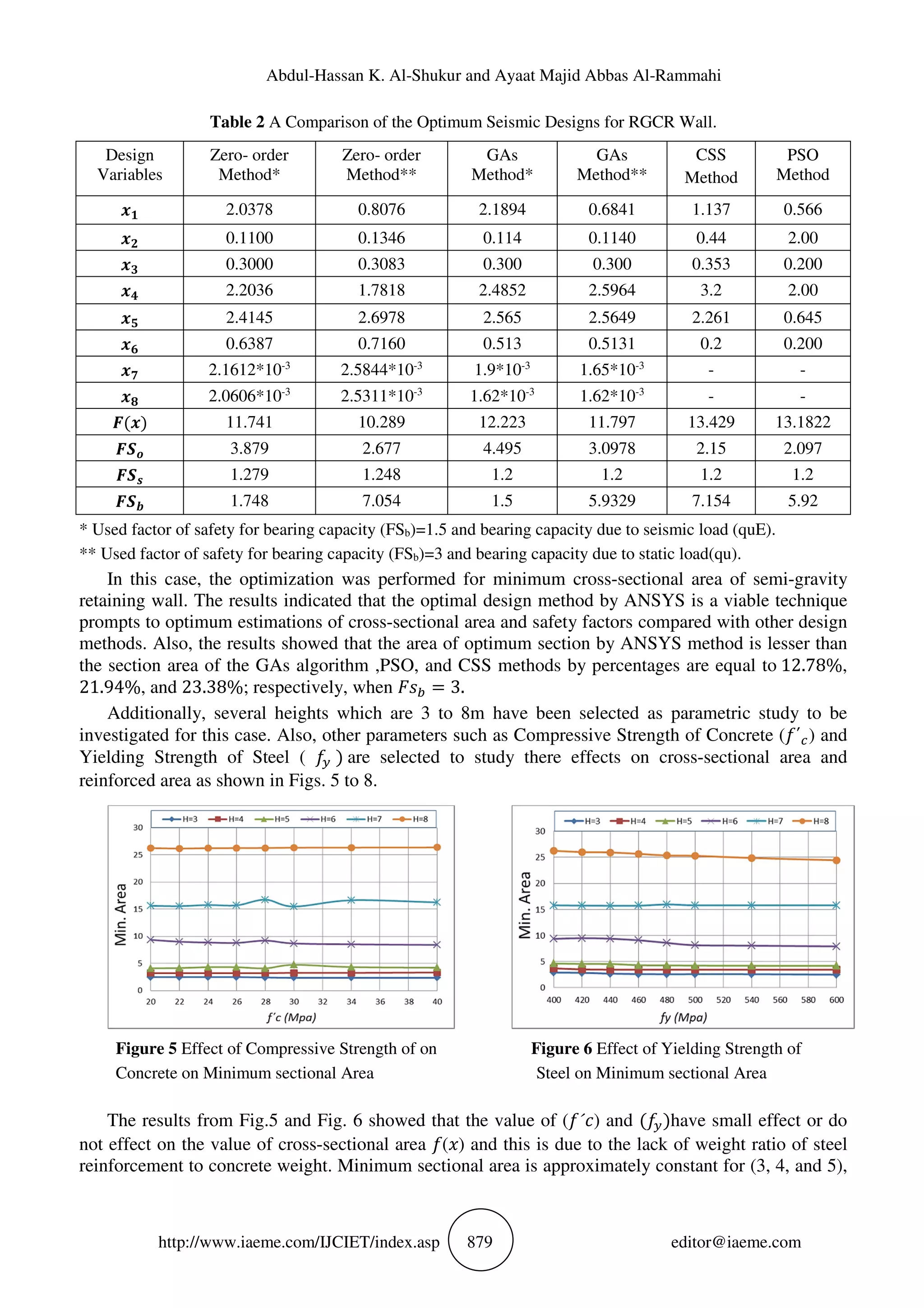
An example is optimized with the Zero-Order method by ANSYS. The final result is compared to
the solution of the Genetic Algorithm Method (GAs) in example [13], Charged System Search (CSS),
the particle swarm optimization (PSO) methods in example [14] to demonstrate the efficiency of the
present approach and the results of the seismic design optimization process for the Zero-order
(subproblem) method and other methods are summarized in Table 2.](https://image.slidesharecdn.com/ijciet0801103-170306060400/75/OPTIMUM-DESIGN-OF-SEMI-GRAVITY-RETAINING-WALL-SUBJECTED-TO-STATIC-AND-SEISMIC-LOADS-6-2048.jpg)
![Optimum Design of Semi-Gravity Retaining Wall Subjected to Static and Seismic Loads
http://www.iaeme.com/IJCIET/index.asp 880 editor@iaeme.com
while for y=6‹, the increment in ( ) value from 400 Mpa to 480 Mpa,which is equal to 20%,
decreases min. area to an amount of 8.14% .
Figure 7 Effect of Compressive Strength of Figure 8 Effect of the Yielding Strength of
Concrete on Reinforced Area Steel on Reinforced Area
From Fig. 7 and Fig. 8, It can be observed that the yielding strength of steel ( ) effects on the
quantity of reinforcement steel area of toe slab ( )) and heel slab ( *).The increment values of
yielding strength of steel ( ) lead to decrease the quantity of reinforcement. Also, the yielding
strength of steel ( Œ) has larger effect than compressive strength of concrete ( ´ ) in the reinforcement
area.
6. CONCLUTION
• The ANSYS / APDL are efficient tool to simulate wall-backfill-foundation interaction problem and
optimization process.
• Through the gathering of optimization module (/OPT) and APDL, the optimal reuse examination is
quick and the results are dependable and sensible.
• The optimum design method by ANSYS is a viable technique prompts to optimum values of
cross‒sectional area with both safety and stability factors as compared with other design methods.
• From design semi-gravity wall under static and seismic loads, it is preferred that the back buttress ( &)
be larger than front buttress ( #) 3 times or more for several reasons, it reduces the lateral earth pressure
and increases the weight of backfill soil on back buttress which leads to an increase in resistance forces
also.
• The yielding strength of steel ( Œ) has larger effect than compressive strength of concrete ( ´ ) in the
reinforcement area.
REFERENCES
[1] Das, B., M., 2011, “Principle of Foundation Engineering”, th7 Edition, Printed in the United States
of America.
[2] FHWA, Federal Highway Administration, 2004, “Seismic Retrofitting Manual for Highway
Structures: Part 2-Retaining Structures, Slopes, Tunnels, Culverts, and Roadways”, Report
No.FHWA-HRT-05-067, Federal Highway Administration, Washington, DC, August.
[3] R. Sheikholeslami, B. G. Khalili, A. Sadollah, and J. H. Kim, 2015 “Optimization Of Reinforced
Concrete Retaining Walls Via Hybrid Firefly Algorithm With Upper Bounded Strategy” KSCE
Journal of Civil Engineering.](https://image.slidesharecdn.com/ijciet0801103-170306060400/75/OPTIMUM-DESIGN-OF-SEMI-GRAVITY-RETAINING-WALL-SUBJECTED-TO-STATIC-AND-SEISMIC-LOADS-8-2048.jpg)
![Abdul-Hassan K. Al-Shukur and Ayaat Majid Abbas Al-Rammahi
http://www.iaeme.com/IJCIET/index.asp 881 editor@iaeme.com
[4] Erol Dsadoglu, 2014 “Optimization For Symmetrical Gravity Retaining Walls” Karadeniz
Technical University, Faculty of Engineering Trabzon, Turkey.
[5] Rao, S., 2009 "Engineering Optimization Theory and Practice", th4 Edition, John Wiley & Sons.
[6] S. Kramer,1996 “Geotechnical Earthquake Engineering”, Prentice Hall.
[7] G. Wu, W.D.L. Finn, 1999 “Seismic lateral pressures for design of rigid walls”. Canadian
Geotechnical Journal, 36(3), 509-522.
[8] M. Kutanis and M. Elmas, 2001 “Non Linear Seismic Soil Structure Interaction Analysis Based On
The Substructure Method In The Time Domaine“. Turk Journal Engineering Environ Sci25 pp 617-
626.
[9] ANSYS. ANSYS User’s Manual,2007 “ANSYS Theory Manual”. Version 11.0.
[10] American Concrete Institute, 2011, “Building Code Requirements for Structural Concrete (ACI
318M-11)”.
[11] American Association of State Highway and Transportation Official, 2012, “AASHTO LRFD
Bridge Design Specifications”, Washington, D.C.R. Sheikholeslami et al.
[12] Truman, K.Z., Hoback, A.S., 1992 “Optimization of steel piles under rigid slab foundations using
optimality criteria”. Structural and Multidisciplinary Optimization, 5, 1, 30-36.
[13] M. K. O. Muhammad, 2014, “Optimal Design of types of Retaining Structures under Static and
Seismic Loads”, University of Babylon, College of Engineering, Department of Civil Engineering,
A dissertation for the Master degree.
[14] A. Kaveh, S. Talatahari and R. Sheikholeslami, 2011, “Optimum Seismic Design of Gravity
Retaining Walls using the Heuristic Big Bang-Big Crunch Algorithm” in Proceedings of the 2nd
International Conference on Soft Computing Technology in Civil, Structural and Environmental
Engineering, B. H. V. Topping and Y. Tsompanakis, Eds., Paper 4, Civil-Comp Press.
[15] K Venkatesh and T. Venkatdas, Study on Seismic Effect of High Rise Building Shear Wall/Wall
Without Shear Wall International Journal of Civil Engineering and Technology 8(1), 2017, pp.
852–862
[16] Mohsin, A.Z., Dr. Omran, H.A. and Dr. Al - Shukur, A. - H.K. Dynamic Response of Concrete
Gravity Dam on Random Soil. International Journal of Civil Engineering and Technology
(IJCIET), 6 (11), 2015, pp. 21-31.](https://image.slidesharecdn.com/ijciet0801103-170306060400/75/OPTIMUM-DESIGN-OF-SEMI-GRAVITY-RETAINING-WALL-SUBJECTED-TO-STATIC-AND-SEISMIC-LOADS-9-2048.jpg)

The document presents research on the optimum design of semi-gravity retaining walls subjected to static and seismic loads using finite element analysis through ANSYS. It explores the effectiveness of various optimization methods in minimizing cross-sectional area while ensuring safety and stability, revealing that the ANSYS method outperforms alternative methods. Key findings include the influence of design parameters such as concrete compressive strength and steel yielding strength on the overall design optimization.


