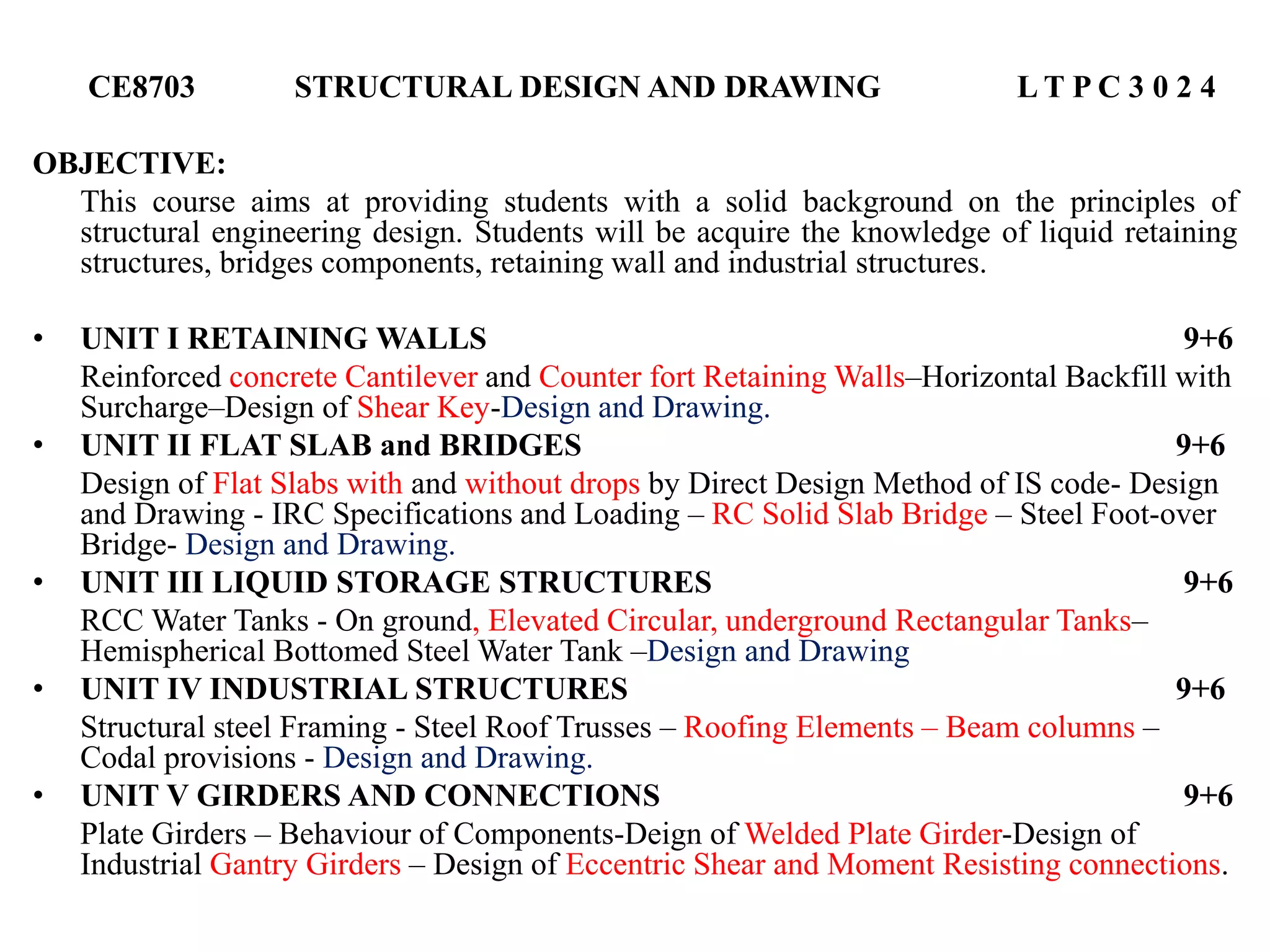
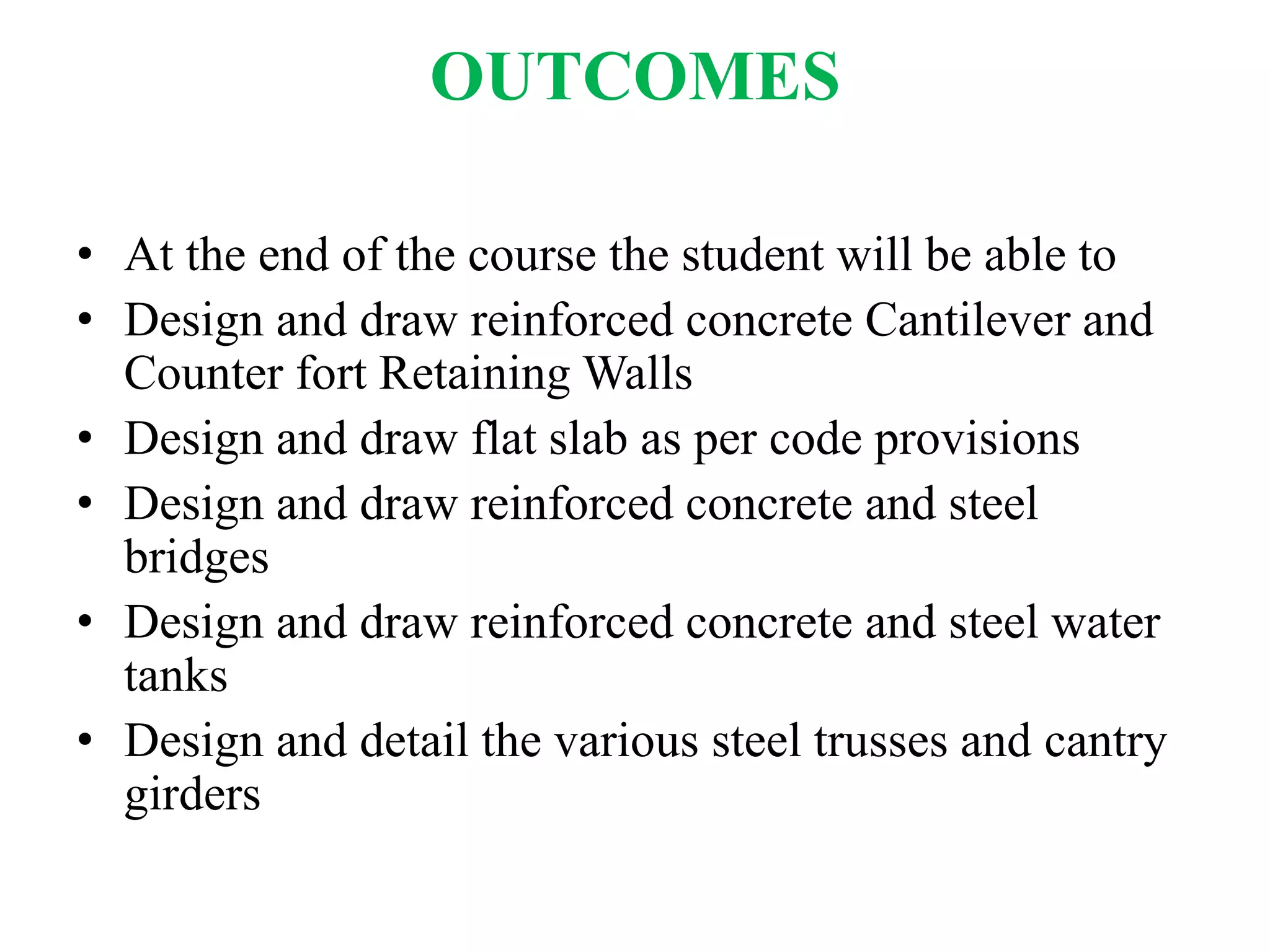
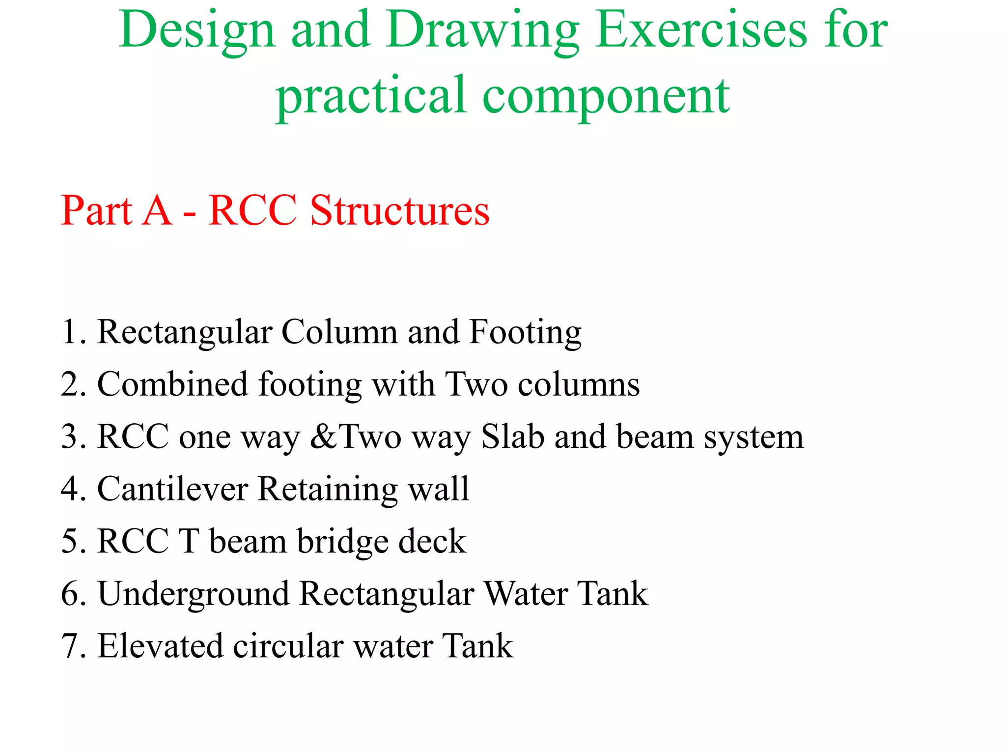
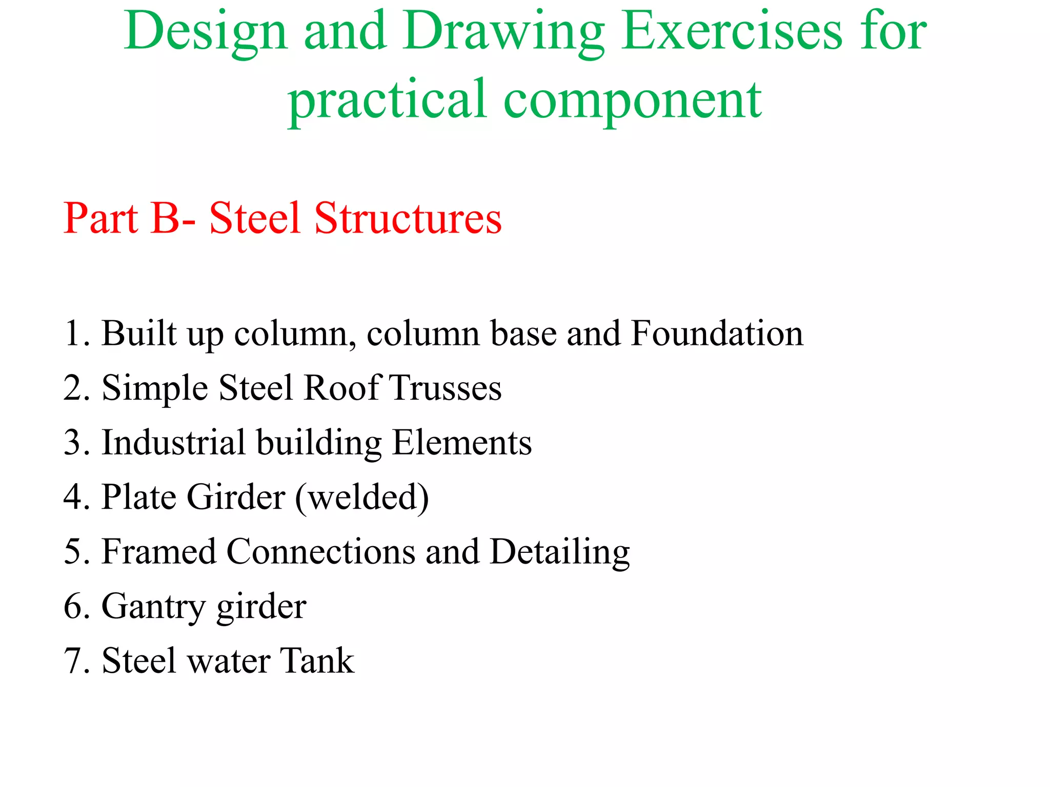
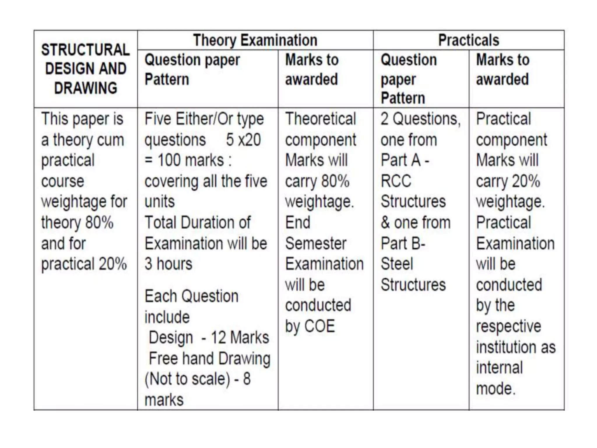
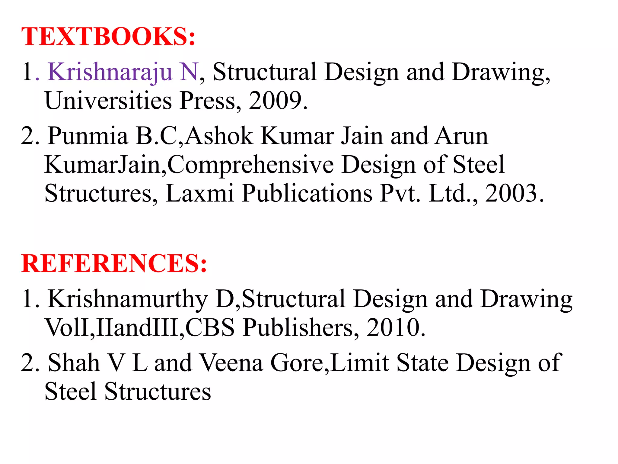
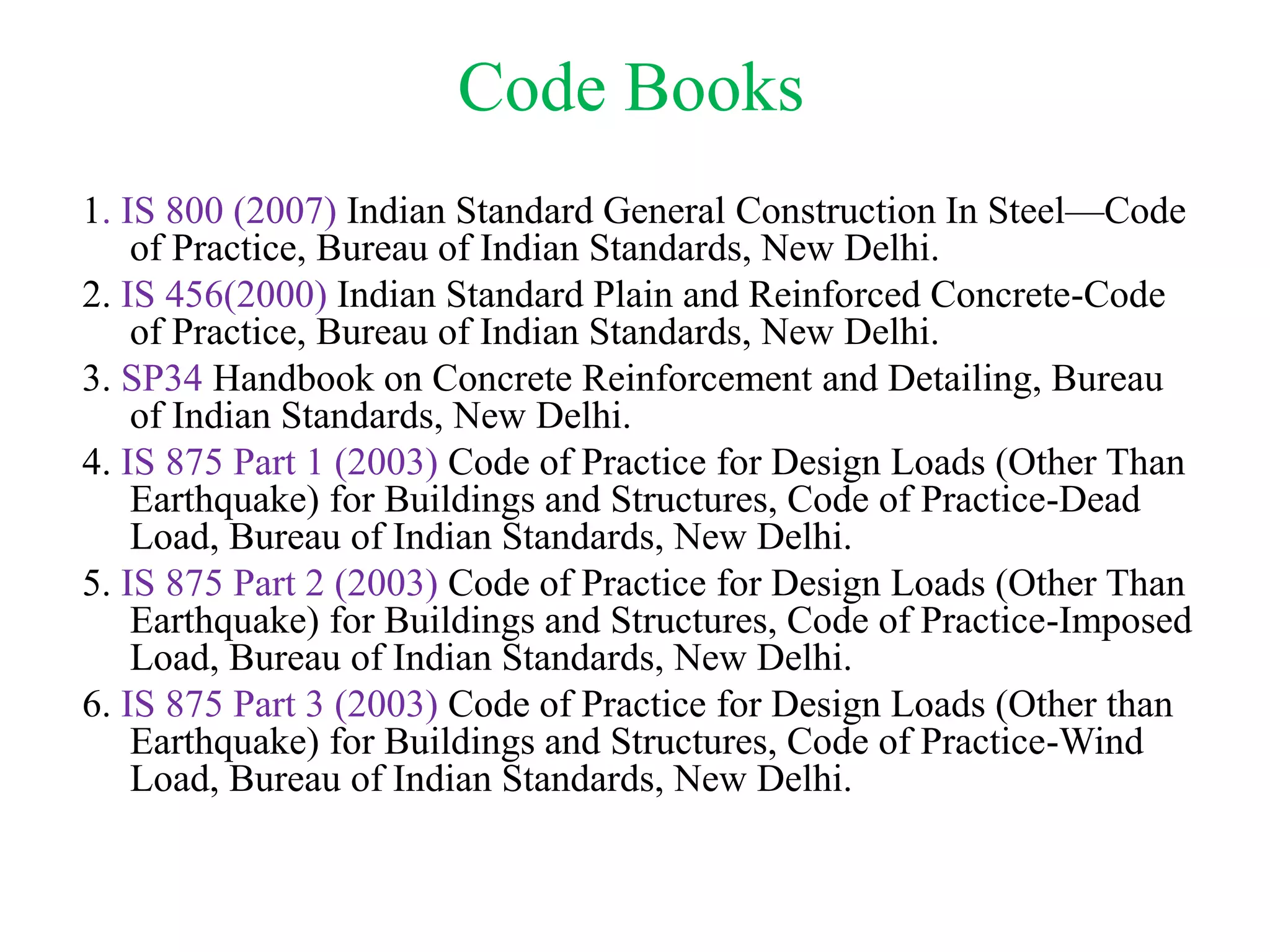
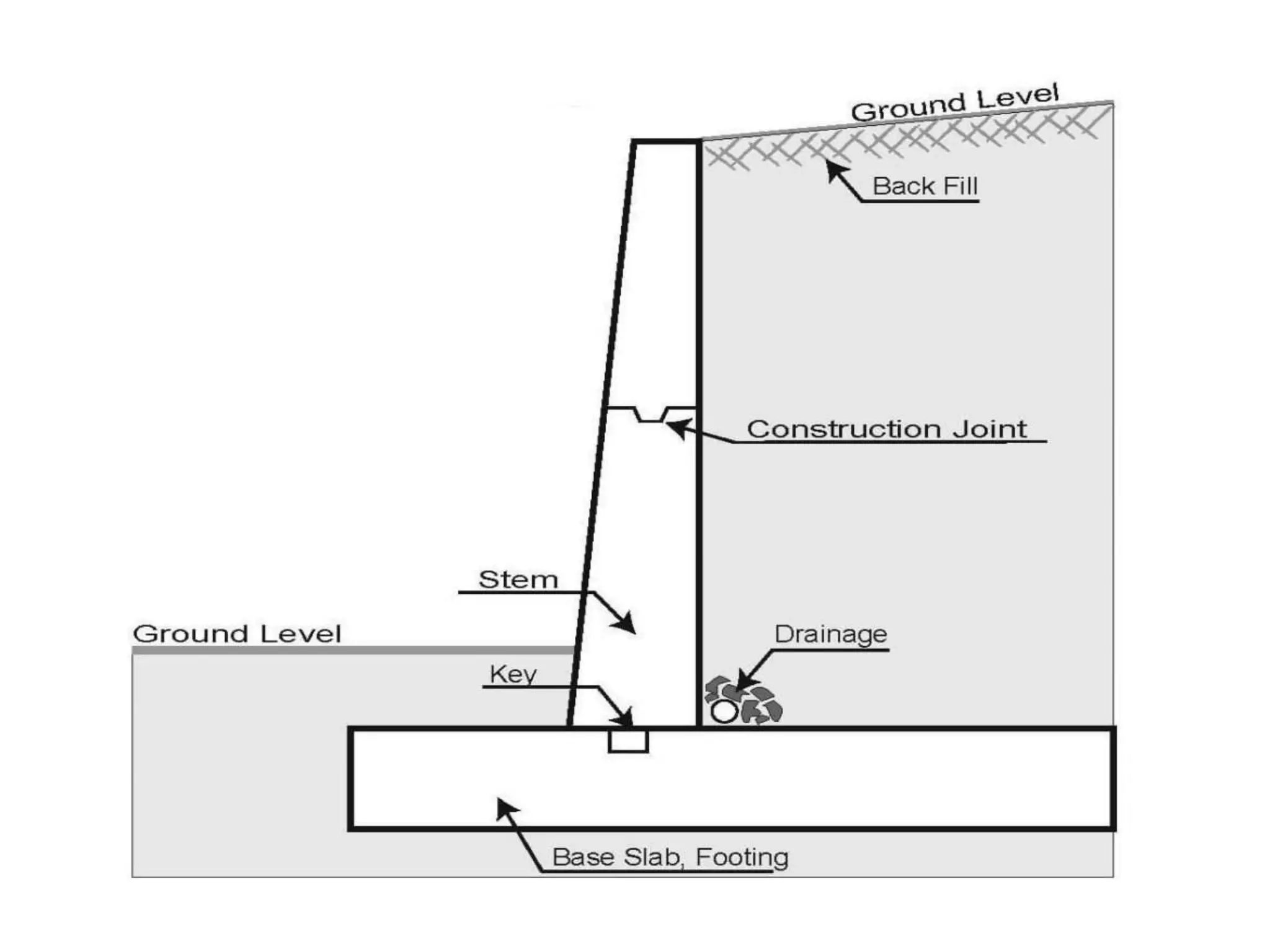
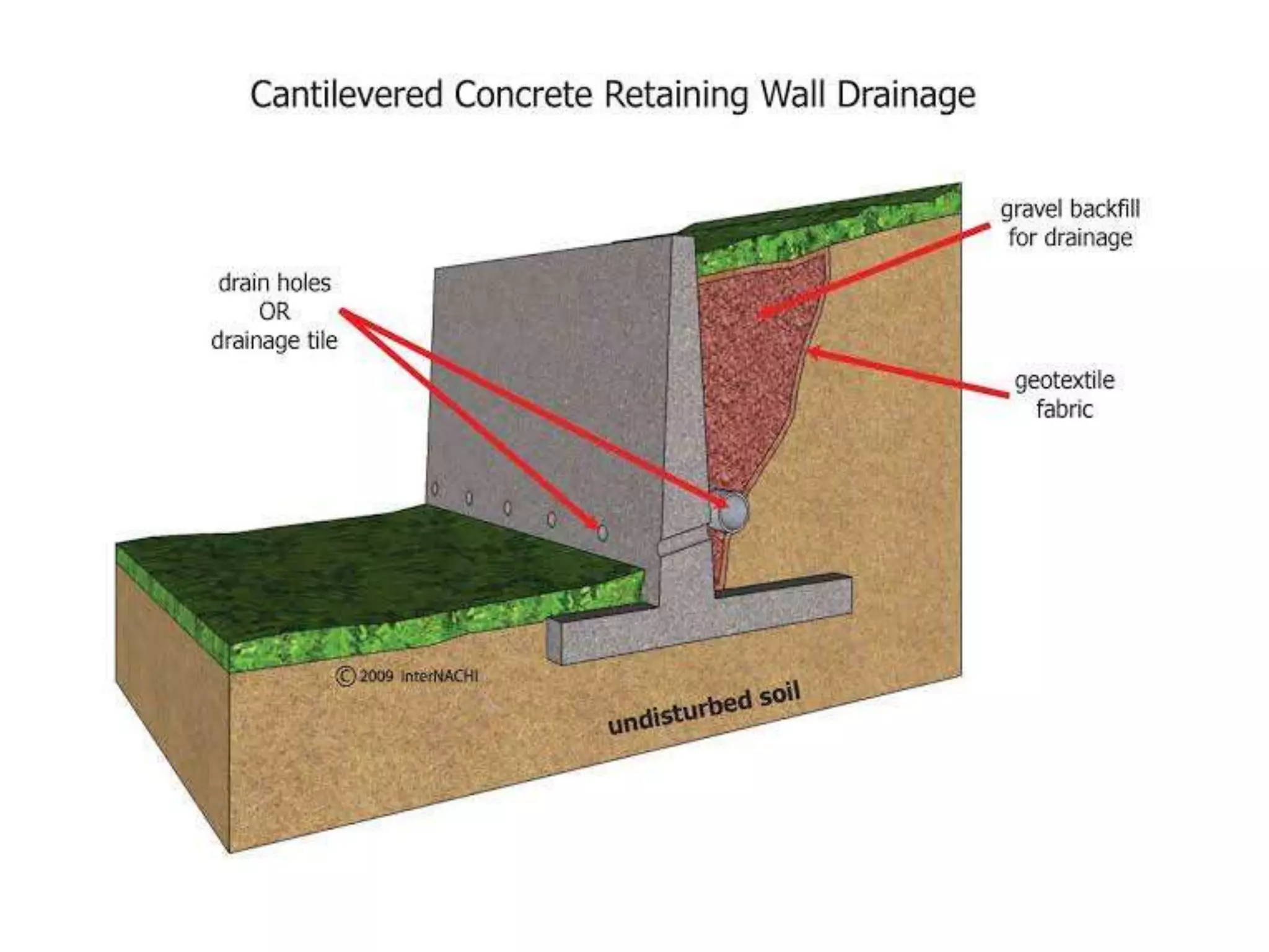
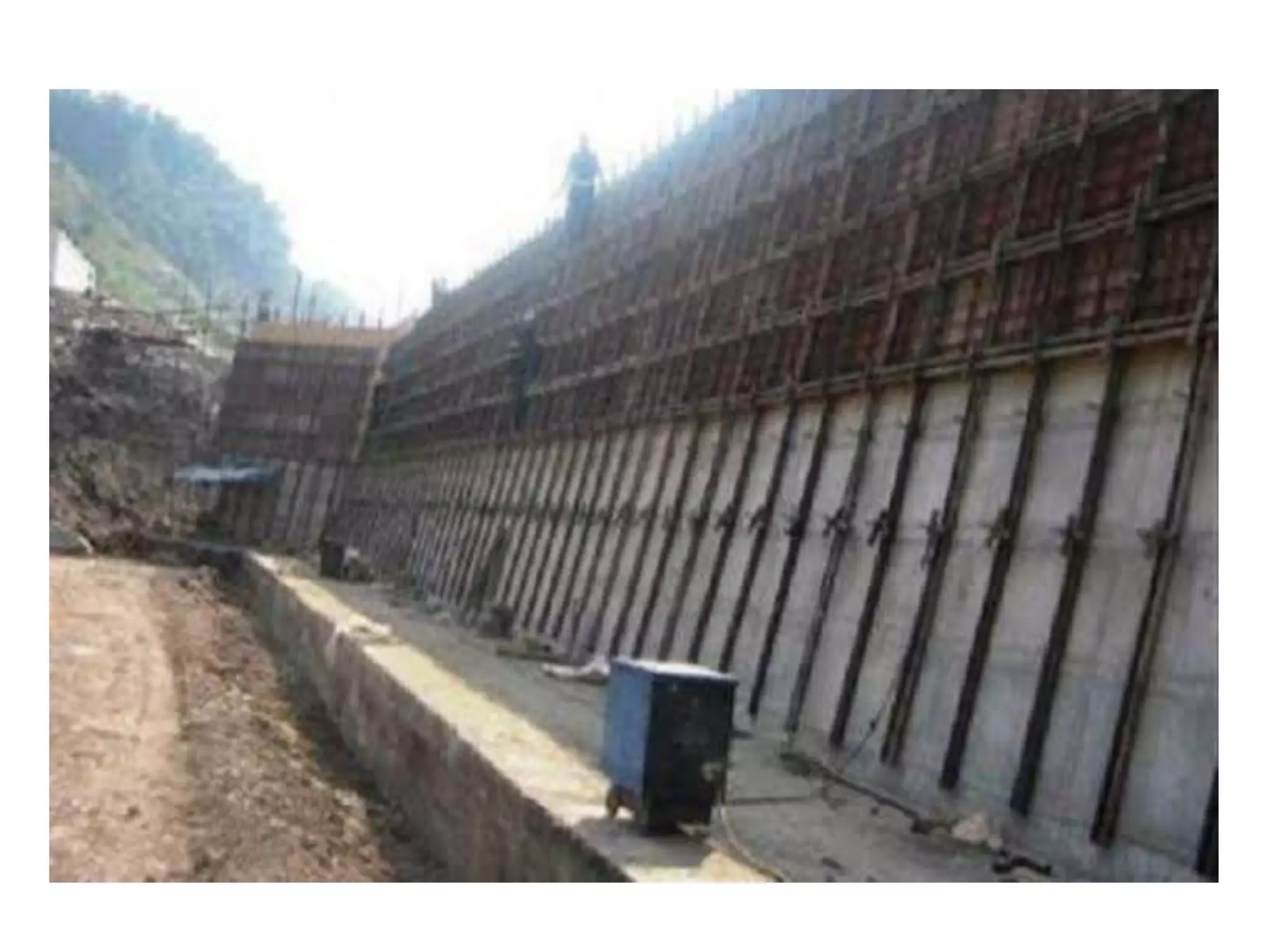
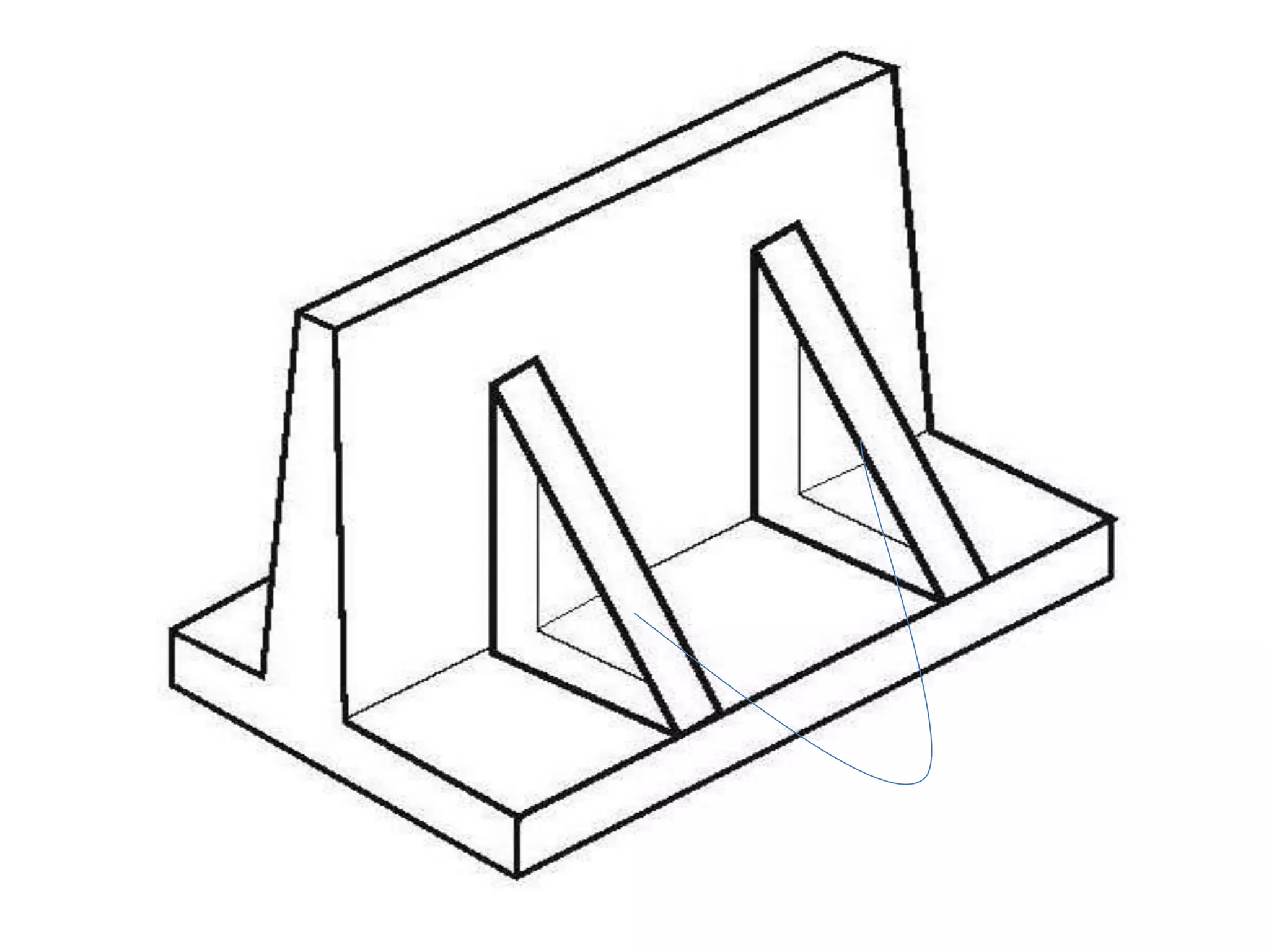
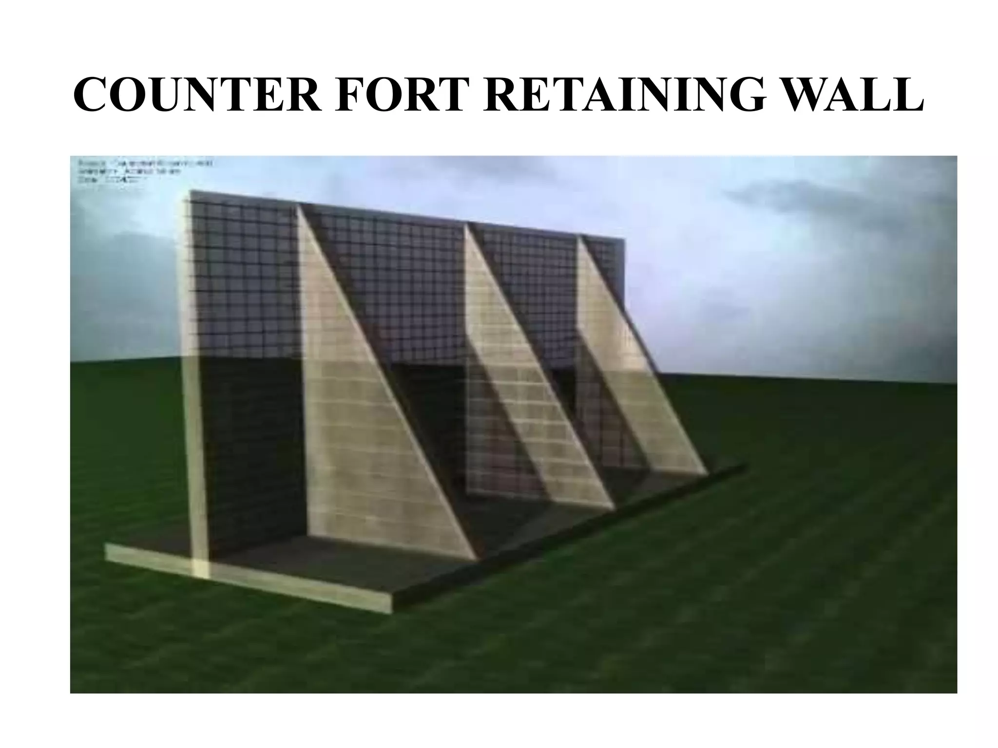
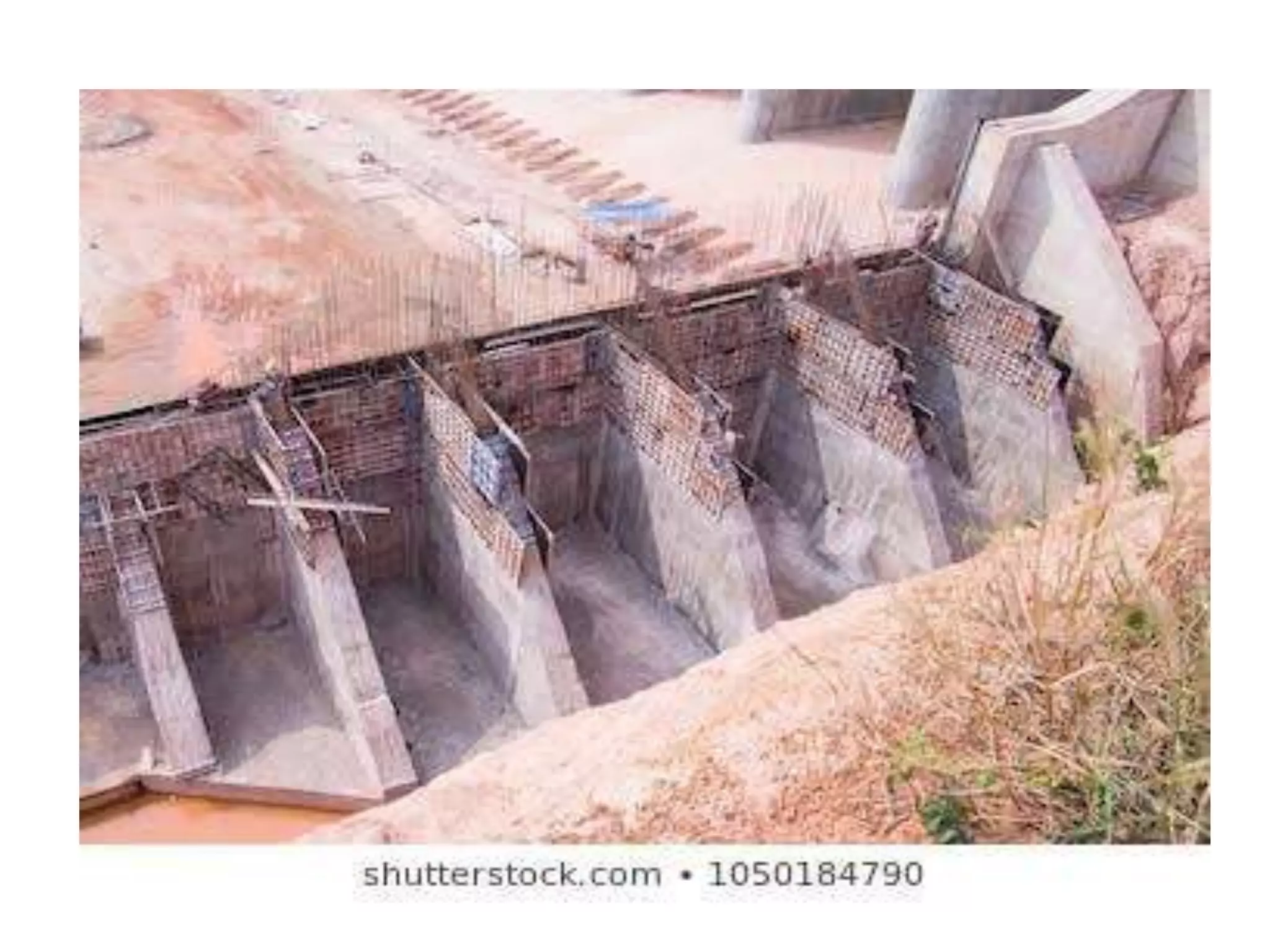
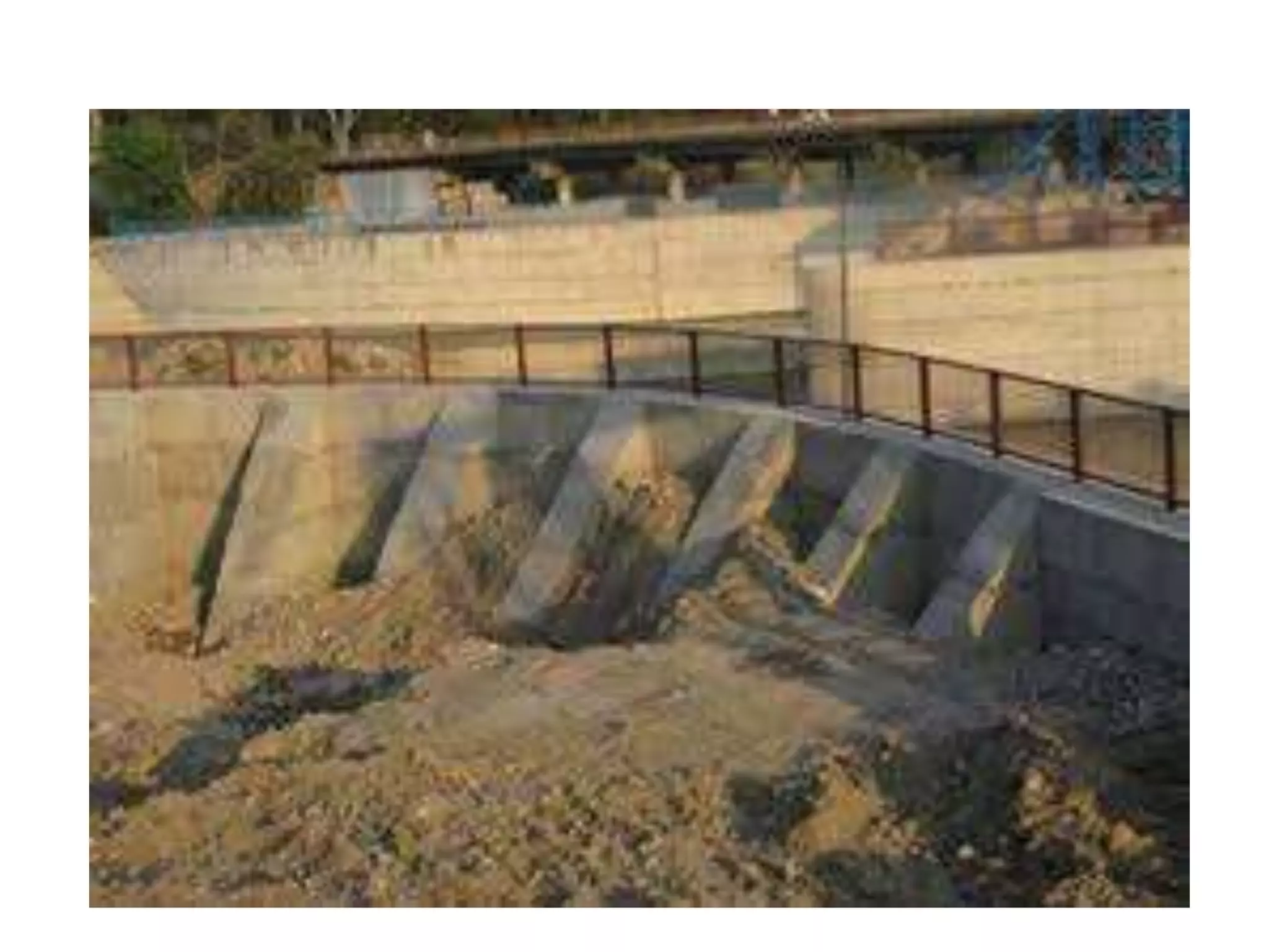
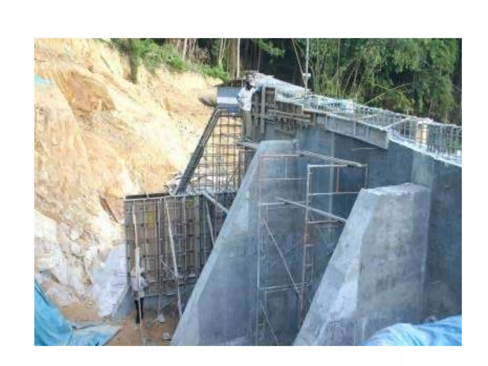
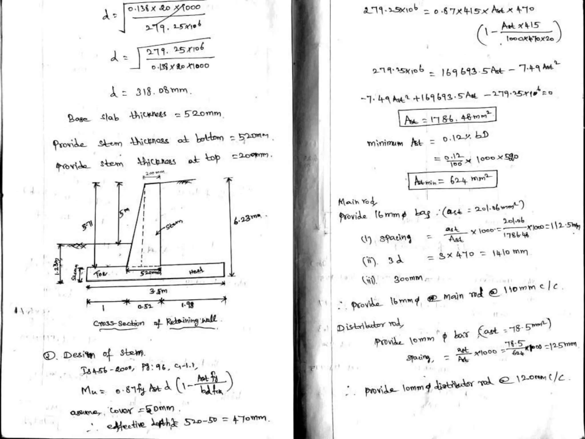
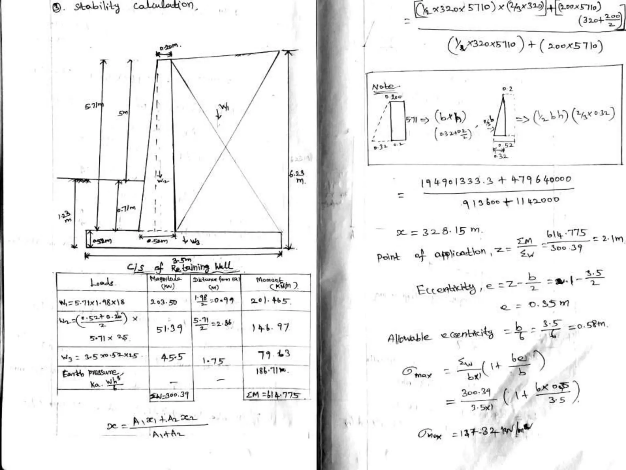
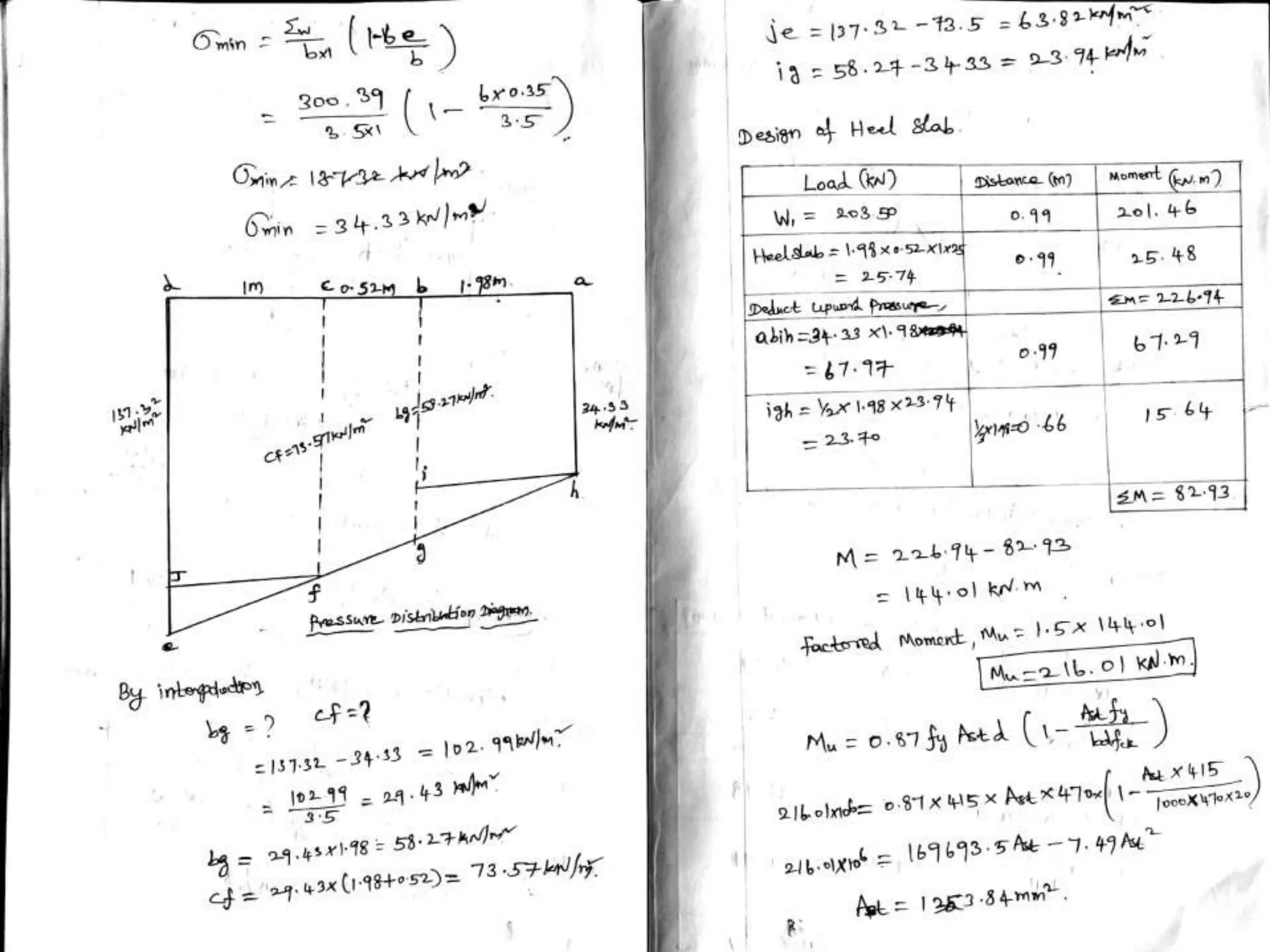
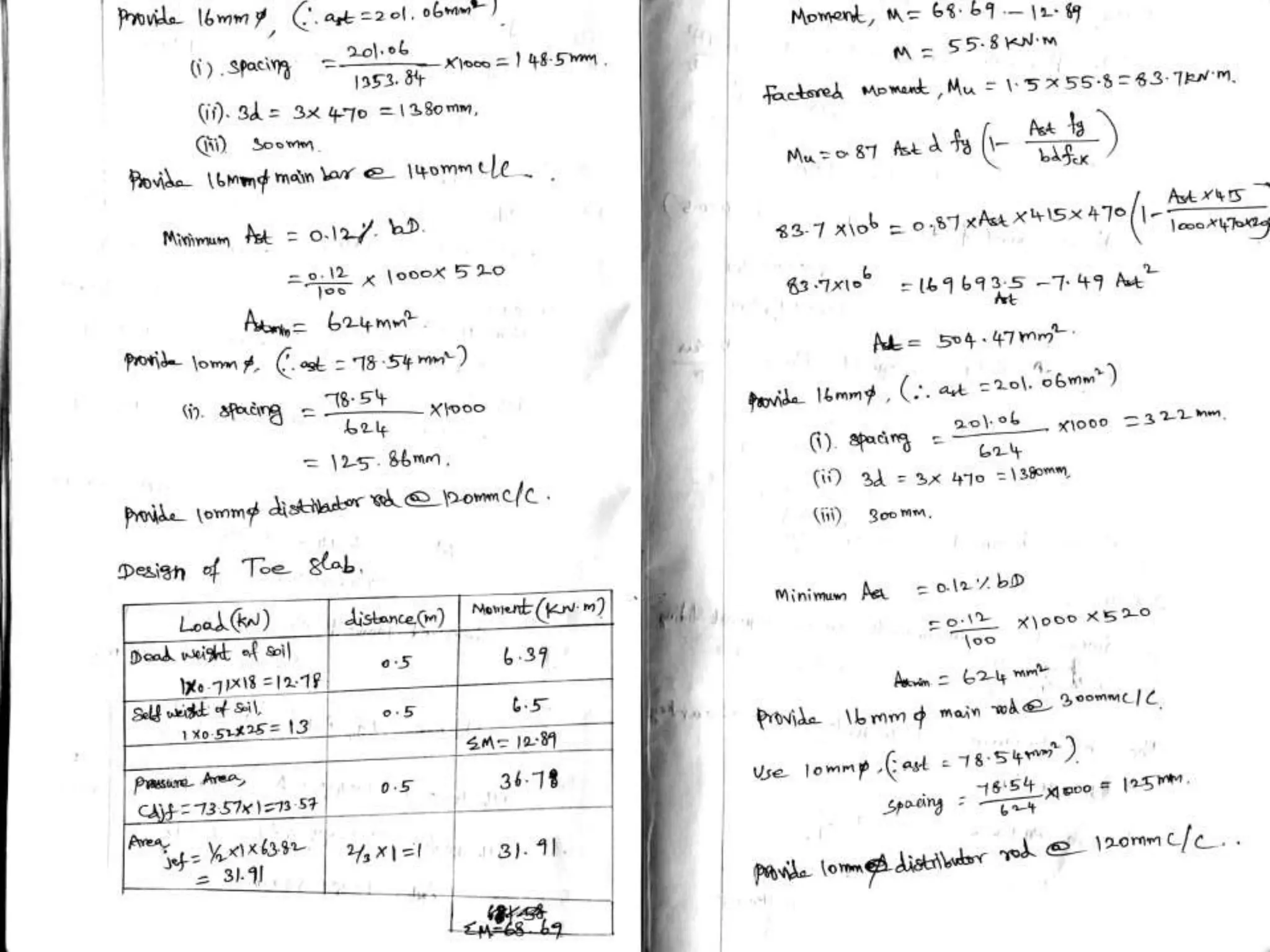
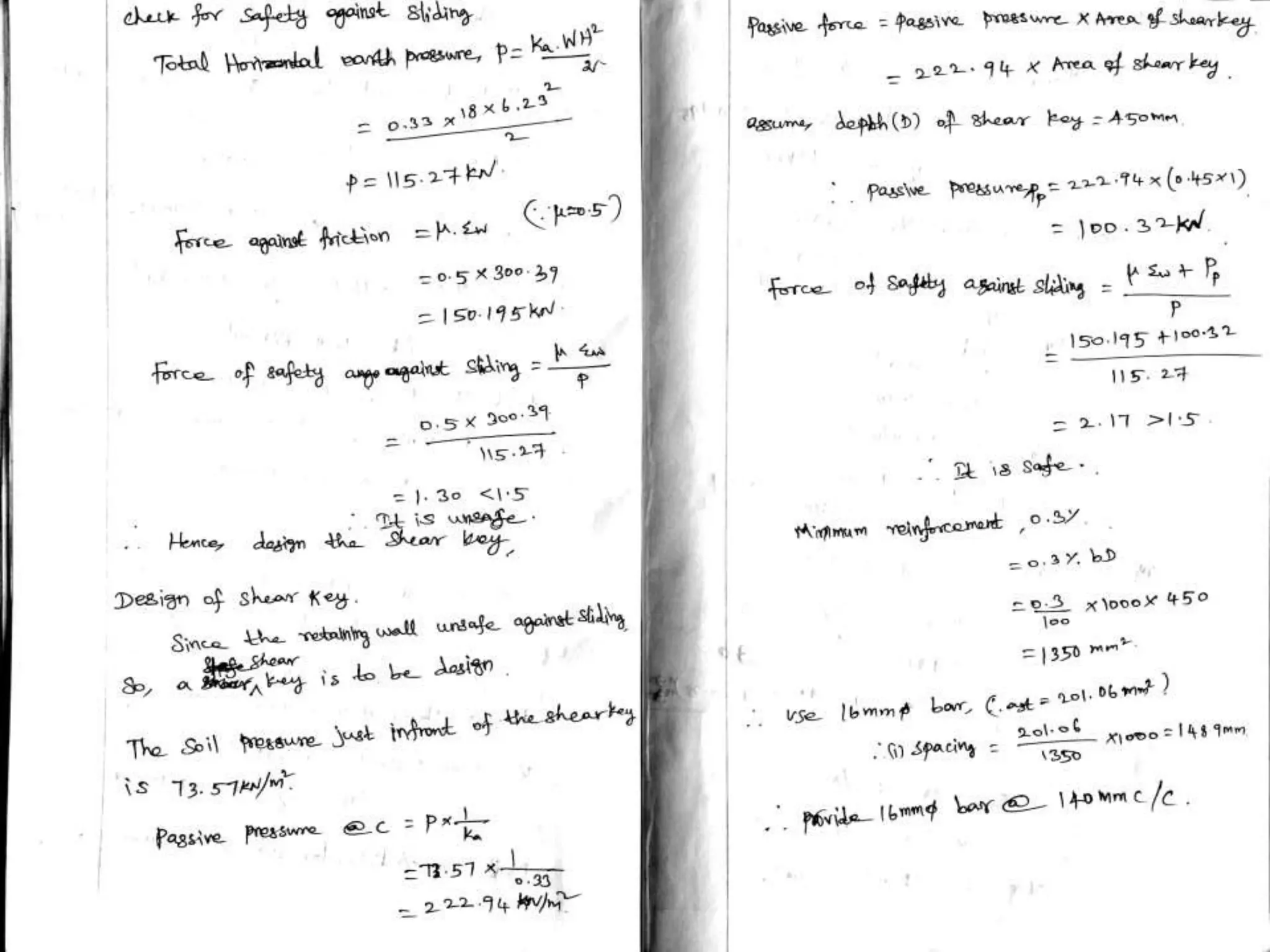
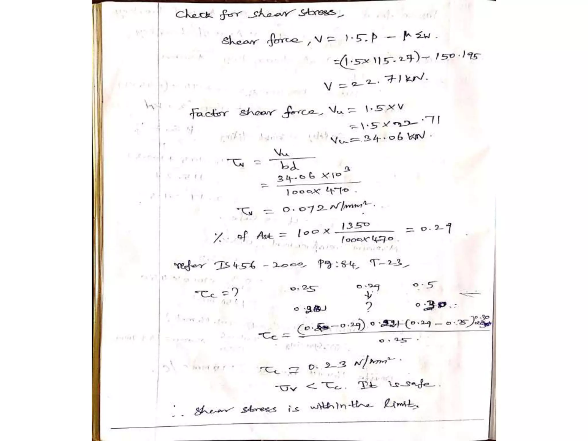
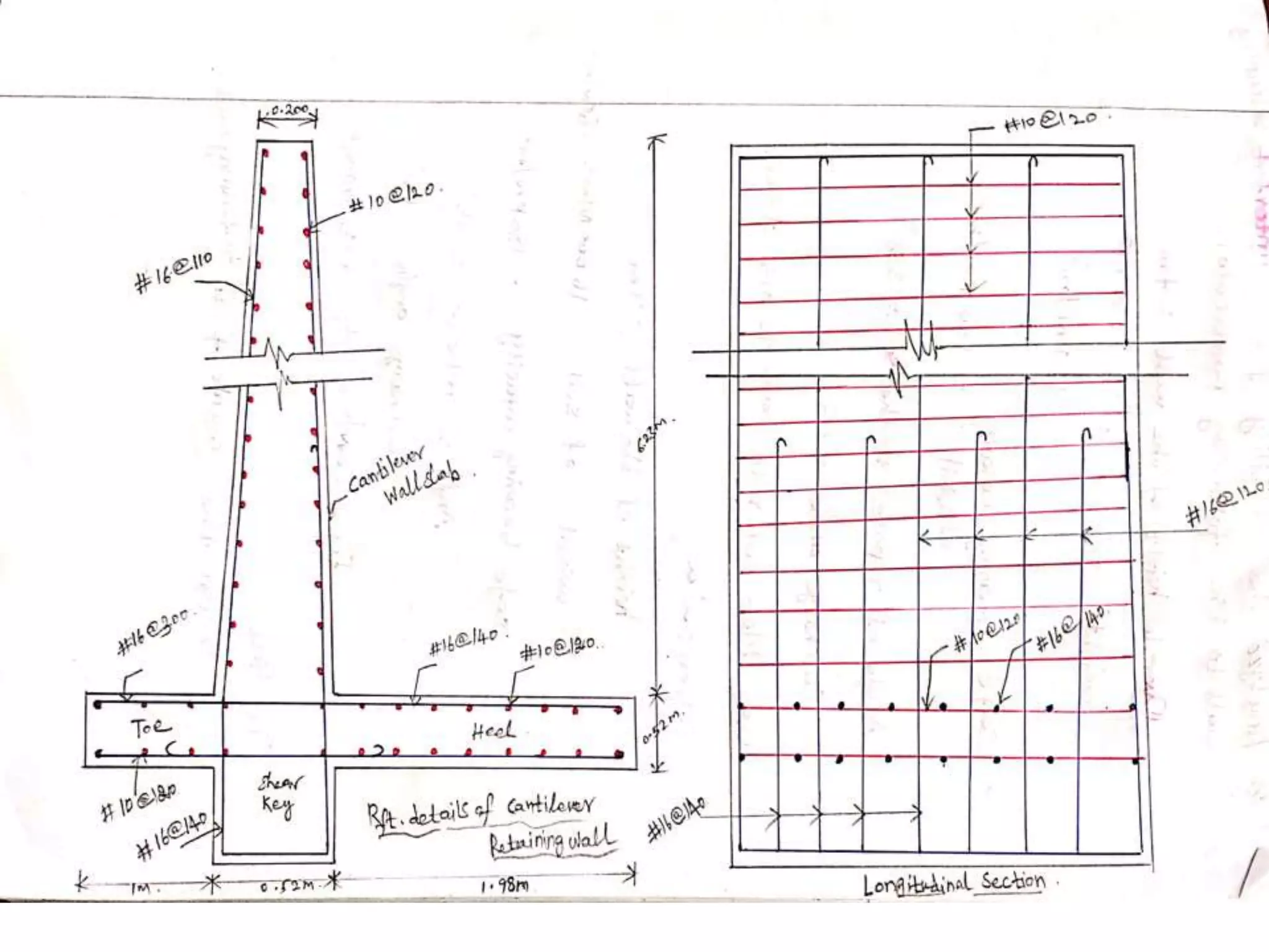
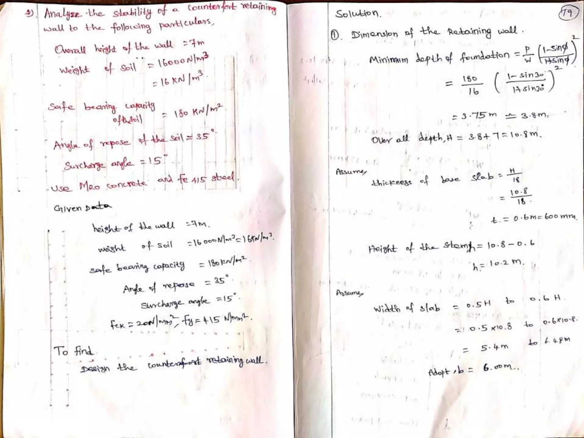
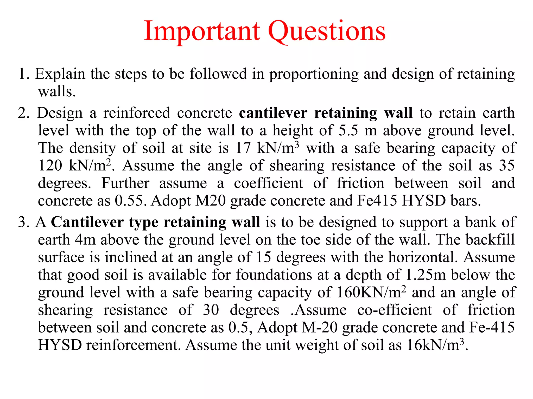
VIVEKANANDHA COLLEGE OF TECHNOLOGY
FOR WOMEN
DEPARTMENT OF CIVIL ENGINEERING
CE8703-STRUCTURAL DESIGN AND DRAWING
By
Mr.A.ANANTHAKUMAR, M.E.,(Ph.D).,
Assistant Professor
CE8703 STRUCTURAL DESIGN AND DRAWING L T P C 3 0 2 4
OBJECTIVE:
This course aims at providing students with a solid background on the principles of
structural engineering design. Students will be acquire the knowledge of liquid retaining
structures, bridges components, retaining wall and industrial structures.
• UNIT I RETAINING WALLS 9+6
Reinforced concrete Cantilever and Counter fort Retaining Walls–Horizontal Backfill with
Surcharge–Design of Shear Key-Design and Drawing.
• UNIT II FLAT SLAB and BRIDGES 9+6
Design of Flat Slabs with and without drops by Direct Design Method of IS code- Design
and Drawing - IRC Specifications and Loading – RC Solid Slab Bridge – Steel Foot-over
Bridge- Design and Drawing.
• UNIT III LIQUID STORAGE STRUCTURES 9+6
RCC Water Tanks - On ground, Elevated Circular, underground Rectangular Tanks–
Hemispherical Bottomed Steel Water Tank –Design and Drawing
• UNIT IV INDUSTRIAL STRUCTURES 9+6
Structural steel Framing - Steel Roof Trusses – Roofing Elements – Beam columns –
Codal provisions - Design and Drawing.
• UNIT V GIRDERS AND CONNECTIONS 9+6
Plate Girders – Behaviour of Components-Deign of Welded Plate Girder-Design of
Industrial Gantry Girders – Design of Eccentric Shear and Moment Resisting connections.
OUTCOMES
• At the end of the course the student will be able to
• Design and draw reinforced concrete Cantilever and
Counter fort Retaining Walls
• Design and draw flat slab as per code provisions
• Design and draw reinforced concrete and steel
bridges
• Design and draw reinforced concrete and steel water
tanks
• Design and detail the various steel trusses and cantry
girders
Design and Drawing Exercises for
practical component
Part A - RCC Structures
1. Rectangular Column and Footing
2. Combined footing with Two columns
3. RCC one way &Two way Slab and beam system
4. Cantilever Retaining wall
5. RCC T beam bridge deck
6. Underground Rectangular Water Tank
7. Elevated circular water Tank
Design and Drawing Exercises for
practical component
Part B- Steel Structures
1. Built up column, column base and Foundation
2. Simple Steel Roof Trusses
3. Industrial building Elements
4. Plate Girder (welded)
5. Framed Connections and Detailing
6. Gantry girder
7. Steel water Tank
TEXTBOOKS:
1. Krishnaraju N, Structural Design and Drawing,
Universities Press, 2009.
2. Punmia B.C,Ashok Kumar Jain and Arun
KumarJain,Comprehensive Design of Steel
Structures, Laxmi Publications Pvt. Ltd., 2003.
REFERENCES:
1. Krishnamurthy D,Structural Design and Drawing
VolI,IIandIII,CBS Publishers, 2010.
2. Shah V L and Veena Gore,Limit State Design of
Steel Structures
Code Books
1. IS 800 (2007) Indian Standard General Construction In Steel—Code
of Practice, Bureau of Indian Standards, New Delhi.
2. IS 456(2000) Indian Standard Plain and Reinforced Concrete-Code
of Practice, Bureau of Indian Standards, New Delhi.
3. SP34 Handbook on Concrete Reinforcement and Detailing, Bureau
of Indian Standards, New Delhi.
4. IS 875 Part 1 (2003) Code of Practice for Design Loads (Other Than
Earthquake) for Buildings and Structures, Code of Practice-Dead
Load, Bureau of Indian Standards, New Delhi.
5. IS 875 Part 2 (2003) Code of Practice for Design Loads (Other Than
Earthquake) for Buildings and Structures, Code of Practice-Imposed
Load, Bureau of Indian Standards, New Delhi.
6. IS 875 Part 3 (2003) Code of Practice for Design Loads (Other than
Earthquake) for Buildings and Structures, Code of Practice-Wind
Load, Bureau of Indian Standards, New Delhi.
Code Books
7. IS 3370 Part 1 (2009) Indian Standard Concrete Structures for Storage of
Liquids-Code of Practice–General Requirements, Code of Practice,
Bureau of Indian Standards, New Delhi.
8. IS 3370 Part 2 (2009) Indian Standard Concrete Structures for Storage of
Liquids-Code of Practice-Reinforced Concrete Structures, Code of
Practice, Bureau of Indian Standards, New Delhi.
9. IS 3370–Part 4 (2008) Indian Standard Code of Practice for Concrete
Structures for The Storage of Liquids-Design Tables, Code of Practice,
Bureau of Indian Standards, New Delhi.
10. IS 804 (2008) Indian Standard Specification for Rectangular Pressed
Steel Tanks, Code of Practice, Bureau of Indian Standards, New Delhi.
11. IS 805 (2006) Indian Standard Code of Practice for Use of Steel in
Gravity Water Tanks, Code of Practice, Bureau of Indian Standards,
New Delhi.
12. IRC 112-2011, Code of Practice for Concrete Road Bridges, The Indian
Roads Congress, New Delhi.
13. IRC 6-2014, Standard Specifications and Code of Practice for Road
Bridges Section: II-Loads and Stresses, The Indian Roads Congress,
New Delhi.
CE8703 STRUCTURAL DESIGN AND
DRAWING
UNIT 1 – RETAINING WALL
Types of Retaining Wall
Cantilever Retaining Wall
Counter fort Retaining Wall
Types of Retaining wall
– Gravity retaining wall
– Cantilever retaining wall
– Counter fort retaining wall
– Buttress retaining wall
– Basement or foundation wall
Active Earth Pressure (AEP)
Active earth pressure is the earth pressure when the wall retaining
the soil moves away from backfill. Because of the movement of
wall soil mass adjacent to the retaining wall tends to break away
from remaining soil mass. Active Earth pressure is the lateral force
exerted by the soil on any structure retaining the soil.
Passive Earth Pressure (PEP)
The pressure or resistance which soil develops in response to
movement of the structure of towards it is called the passive earth
pressure.
Define - Retaining wall
Retaining walls are generally used to retain earth or such materials to
maintain unequal levels on its two faces. The soil on the back face is
at a higher level and is called back fill. Retaining walls are extensively
used in the construction of basements below ground level, wing walls
of bridge and to retain slopes in hilly terrain roads.
Forces acting on a Retaining wall
Forces acting on a retaining wall are
 Lateral earth pressure due to the back fill
 Vertical forces including weight of soil, stem, heel, toe, and soil fill
above the toe.
 The soil pressure developed to resist the earth pressure and other
vertical forces acting on the heel and toe.
Cantilever Retaining Wall
Cantilever retaining wall are constructed of
reinforced concrete. Cantilever retaining wall consists of
a relatively thin stem and a base slab. The base is divided
into two parts, namely the heel and toe.
The heel is the part of the base under the backfill and
the toe is the other part of the base. It uses much less
concrete than monolithic gravity walls, but requires more
design and careful construction. It can be formed on site
or precast in a factory.
Shear key
Shear key is a structural element which is sometimes
used in the footing of retaining walls to reduce wall’s
sliding.
There has not been much study about the effect of
shear key in the footing of retaining wall on its seismic
behaviour.
Counter fort Retaining Wall
Counter fort retaining wall are same as cantilever
walls except they have thin vertical concrete webs at
regular intervals along the backside of the wall and these
webs are known as counter forts.
The counter forts tie the slab and base together, and
the purpose of them is to reduce the bending moments
and shear forces secondary effect of these webs is to
increase the weight of the wall from the added concrete.
It can be precast or formed on site.
COUNTER FORT RETAINING WALL
Important Questions
1. Explain the steps to be followed in proportioning and design of retaining
walls.
2. Design a reinforced concrete cantilever retaining wall to retain earth
level with the top of the wall to a height of 5.5 m above ground level.
The density of soil at site is 17 kN/m3 with a safe bearing capacity of
120 kN/m2. Assume the angle of shearing resistance of the soil as 35
degrees. Further assume a coefficient of friction between soil and
concrete as 0.55. Adopt M20 grade concrete and Fe415 HYSD bars.
3. A Cantilever type retaining wall is to be designed to support a bank of
earth 4m above the ground level on the toe side of the wall. The backfill
surface is inclined at an angle of 15 degrees with the horizontal. Assume
that good soil is available for foundations at a depth of 1.25m below the
ground level with a safe bearing capacity of 160KN/m2 and an angle of
shearing resistance of 30 degrees .Assume co-efficient of friction
between soil and concrete as 0.5, Adopt M-20 grade concrete and Fe-415
HYSD reinforcement. Assume the unit weight of soil as 16kN/m3.
4. Design a counter fort type retaining wall to support an earth fill of
7.5m above
ground level. The foundation depth may be taken as 1.5m below the
ground level. The safe bearing capacity of soil at site is 150KN/m2. Unit
weight of soil may be taken as 16KN/m3 and an angle of shearing
resistance of 30degrees. Assume the value of coefficient of friction as
0.55. Adopt M-20 grade concrete and Fe-415 HYSD bars. Sketch the
details of reinforcements in the retaining wall.
5. Design a cantilever retaining wall to retain earth with a backfill sloped
20 degrees to the horizontal .The top of the wall is 5.5m above the
ground level. Assume the depth of foundation as 1.2 m below the ground
level with a safe bearing capacity of capacity of 120kN/m2. The unit
weight of backfill is 18KN/m3 and an angle of shearing resistance of
35degrees. Also assume the coefficient of friction between soil and
concrete as 0.55. Adopt M-20 grade concrete and Fe-415HYSD steel
bars.
6. Design a cantilever retaining wall to retain 5m of horizontal backfill.
The density of the soil is 17kN/m3
Safe bearing capacity of the soil = 165 kN/m2
Angle of internal friction of soil = 250
The co-efficient of friction between base slab and concrete = 0.55
Use M20 concrete and Fe415 steel.
7. Design a cantilever retaining wall for the following data
Height of the wall above ground = 4m
Depth of foundation = 1.5m
Unit weight of earth fill = 17 kN/m2
Safe bearing capacity of the soil = 130 kN/m2
The coefficient of friction between base slab and concrete = 0.45
8. Design a cantilever retaining wall to retain earth embankment 3m high above
the ground level. The unit weight of earth is 18 kN/m3 and its angle of repose is
300, safe bearing capacity of soil is 100 kN/m2 and the coefficient of friction
between soil and concrete is 0.5. Adopt M20 concrete and Fe415 steel.
9. A counter fort retaining wall 5m high above foundation level supports
earth with horizontal fill.
Safe bearing capacity of the soil = 200 kN/m2
Angle of internal friction of soil = 300
The coefficient of friction between base slab and concrete = 0.5
Unit weight of backfill is 16 kN/m3
Determine suitable dimension of base slab for stability considerations.
10. Design a T shaped cantilever retaining wall for the following data.
Height of the wall above ground = 3.5m
Depth of foundation = 1.3m
Safe bearing capacity of the soil = 140 kN/m2
Angle of internal friction of soil = 250
The coefficient of friction between base slab and concrete = 0.44
Unit weight of earth fill is 18 kN/m3
Adopt M20 grade concrete and Fe415 grade steel.
11. Explain the methods of designing shear key in a retaining wall.
12. Design stem and counter fort portion of a retaining wall for the
following data.
Height of the wall = 8.7m
Density of soil = 18 kN/m3
Spacing of counter fort = 3.5m
Angle of internal friction of soil = 300
Safe bearing capacity of the soil = 170 kN/m2
Adopt M20 grade concrete and Fe415 grade steel.
Sketch the reinforcement details. Stability check is not necessary.
THANK YOU…
Stay Home… Save Life…

Design of Retaining Wall

  • 1.
    VIVEKANANDHA COLLEGE OFTECHNOLOGY FOR WOMEN DEPARTMENT OF CIVIL ENGINEERING CE8703-STRUCTURAL DESIGN AND DRAWING By Mr.A.ANANTHAKUMAR, M.E.,(Ph.D)., Assistant Professor
  • 2.
    CE8703 STRUCTURAL DESIGNAND DRAWING L T P C 3 0 2 4 OBJECTIVE: This course aims at providing students with a solid background on the principles of structural engineering design. Students will be acquire the knowledge of liquid retaining structures, bridges components, retaining wall and industrial structures. • UNIT I RETAINING WALLS 9+6 Reinforced concrete Cantilever and Counter fort Retaining Walls–Horizontal Backfill with Surcharge–Design of Shear Key-Design and Drawing. • UNIT II FLAT SLAB and BRIDGES 9+6 Design of Flat Slabs with and without drops by Direct Design Method of IS code- Design and Drawing - IRC Specifications and Loading – RC Solid Slab Bridge – Steel Foot-over Bridge- Design and Drawing. • UNIT III LIQUID STORAGE STRUCTURES 9+6 RCC Water Tanks - On ground, Elevated Circular, underground Rectangular Tanks– Hemispherical Bottomed Steel Water Tank –Design and Drawing • UNIT IV INDUSTRIAL STRUCTURES 9+6 Structural steel Framing - Steel Roof Trusses – Roofing Elements – Beam columns – Codal provisions - Design and Drawing. • UNIT V GIRDERS AND CONNECTIONS 9+6 Plate Girders – Behaviour of Components-Deign of Welded Plate Girder-Design of Industrial Gantry Girders – Design of Eccentric Shear and Moment Resisting connections.
  • 3.
    OUTCOMES • At theend of the course the student will be able to • Design and draw reinforced concrete Cantilever and Counter fort Retaining Walls • Design and draw flat slab as per code provisions • Design and draw reinforced concrete and steel bridges • Design and draw reinforced concrete and steel water tanks • Design and detail the various steel trusses and cantry girders
  • 4.
    Design and DrawingExercises for practical component Part A - RCC Structures 1. Rectangular Column and Footing 2. Combined footing with Two columns 3. RCC one way &Two way Slab and beam system 4. Cantilever Retaining wall 5. RCC T beam bridge deck 6. Underground Rectangular Water Tank 7. Elevated circular water Tank
  • 5.
    Design and DrawingExercises for practical component Part B- Steel Structures 1. Built up column, column base and Foundation 2. Simple Steel Roof Trusses 3. Industrial building Elements 4. Plate Girder (welded) 5. Framed Connections and Detailing 6. Gantry girder 7. Steel water Tank
  • 7.
    TEXTBOOKS: 1. Krishnaraju N,Structural Design and Drawing, Universities Press, 2009. 2. Punmia B.C,Ashok Kumar Jain and Arun KumarJain,Comprehensive Design of Steel Structures, Laxmi Publications Pvt. Ltd., 2003. REFERENCES: 1. Krishnamurthy D,Structural Design and Drawing VolI,IIandIII,CBS Publishers, 2010. 2. Shah V L and Veena Gore,Limit State Design of Steel Structures
  • 8.
    Code Books 1. IS800 (2007) Indian Standard General Construction In Steel—Code of Practice, Bureau of Indian Standards, New Delhi. 2. IS 456(2000) Indian Standard Plain and Reinforced Concrete-Code of Practice, Bureau of Indian Standards, New Delhi. 3. SP34 Handbook on Concrete Reinforcement and Detailing, Bureau of Indian Standards, New Delhi. 4. IS 875 Part 1 (2003) Code of Practice for Design Loads (Other Than Earthquake) for Buildings and Structures, Code of Practice-Dead Load, Bureau of Indian Standards, New Delhi. 5. IS 875 Part 2 (2003) Code of Practice for Design Loads (Other Than Earthquake) for Buildings and Structures, Code of Practice-Imposed Load, Bureau of Indian Standards, New Delhi. 6. IS 875 Part 3 (2003) Code of Practice for Design Loads (Other than Earthquake) for Buildings and Structures, Code of Practice-Wind Load, Bureau of Indian Standards, New Delhi.
  • 9.
    Code Books 7. IS3370 Part 1 (2009) Indian Standard Concrete Structures for Storage of Liquids-Code of Practice–General Requirements, Code of Practice, Bureau of Indian Standards, New Delhi. 8. IS 3370 Part 2 (2009) Indian Standard Concrete Structures for Storage of Liquids-Code of Practice-Reinforced Concrete Structures, Code of Practice, Bureau of Indian Standards, New Delhi. 9. IS 3370–Part 4 (2008) Indian Standard Code of Practice for Concrete Structures for The Storage of Liquids-Design Tables, Code of Practice, Bureau of Indian Standards, New Delhi. 10. IS 804 (2008) Indian Standard Specification for Rectangular Pressed Steel Tanks, Code of Practice, Bureau of Indian Standards, New Delhi. 11. IS 805 (2006) Indian Standard Code of Practice for Use of Steel in Gravity Water Tanks, Code of Practice, Bureau of Indian Standards, New Delhi. 12. IRC 112-2011, Code of Practice for Concrete Road Bridges, The Indian Roads Congress, New Delhi. 13. IRC 6-2014, Standard Specifications and Code of Practice for Road Bridges Section: II-Loads and Stresses, The Indian Roads Congress, New Delhi.
  • 10.
    CE8703 STRUCTURAL DESIGNAND DRAWING UNIT 1 – RETAINING WALL Types of Retaining Wall Cantilever Retaining Wall Counter fort Retaining Wall
  • 11.
    Types of Retainingwall – Gravity retaining wall – Cantilever retaining wall – Counter fort retaining wall – Buttress retaining wall – Basement or foundation wall
  • 12.
    Active Earth Pressure(AEP) Active earth pressure is the earth pressure when the wall retaining the soil moves away from backfill. Because of the movement of wall soil mass adjacent to the retaining wall tends to break away from remaining soil mass. Active Earth pressure is the lateral force exerted by the soil on any structure retaining the soil. Passive Earth Pressure (PEP) The pressure or resistance which soil develops in response to movement of the structure of towards it is called the passive earth pressure.
  • 14.
    Define - Retainingwall Retaining walls are generally used to retain earth or such materials to maintain unequal levels on its two faces. The soil on the back face is at a higher level and is called back fill. Retaining walls are extensively used in the construction of basements below ground level, wing walls of bridge and to retain slopes in hilly terrain roads. Forces acting on a Retaining wall Forces acting on a retaining wall are  Lateral earth pressure due to the back fill  Vertical forces including weight of soil, stem, heel, toe, and soil fill above the toe.  The soil pressure developed to resist the earth pressure and other vertical forces acting on the heel and toe.
  • 15.
    Cantilever Retaining Wall Cantileverretaining wall are constructed of reinforced concrete. Cantilever retaining wall consists of a relatively thin stem and a base slab. The base is divided into two parts, namely the heel and toe. The heel is the part of the base under the backfill and the toe is the other part of the base. It uses much less concrete than monolithic gravity walls, but requires more design and careful construction. It can be formed on site or precast in a factory.
  • 16.
    Shear key Shear keyis a structural element which is sometimes used in the footing of retaining walls to reduce wall’s sliding. There has not been much study about the effect of shear key in the footing of retaining wall on its seismic behaviour.
  • 20.
    Counter fort RetainingWall Counter fort retaining wall are same as cantilever walls except they have thin vertical concrete webs at regular intervals along the backside of the wall and these webs are known as counter forts. The counter forts tie the slab and base together, and the purpose of them is to reduce the bending moments and shear forces secondary effect of these webs is to increase the weight of the wall from the added concrete. It can be precast or formed on site.
  • 22.
  • 44.
    Important Questions 1. Explainthe steps to be followed in proportioning and design of retaining walls. 2. Design a reinforced concrete cantilever retaining wall to retain earth level with the top of the wall to a height of 5.5 m above ground level. The density of soil at site is 17 kN/m3 with a safe bearing capacity of 120 kN/m2. Assume the angle of shearing resistance of the soil as 35 degrees. Further assume a coefficient of friction between soil and concrete as 0.55. Adopt M20 grade concrete and Fe415 HYSD bars. 3. A Cantilever type retaining wall is to be designed to support a bank of earth 4m above the ground level on the toe side of the wall. The backfill surface is inclined at an angle of 15 degrees with the horizontal. Assume that good soil is available for foundations at a depth of 1.25m below the ground level with a safe bearing capacity of 160KN/m2 and an angle of shearing resistance of 30 degrees .Assume co-efficient of friction between soil and concrete as 0.5, Adopt M-20 grade concrete and Fe-415 HYSD reinforcement. Assume the unit weight of soil as 16kN/m3.
  • 45.
    4. Design acounter fort type retaining wall to support an earth fill of 7.5m above ground level. The foundation depth may be taken as 1.5m below the ground level. The safe bearing capacity of soil at site is 150KN/m2. Unit weight of soil may be taken as 16KN/m3 and an angle of shearing resistance of 30degrees. Assume the value of coefficient of friction as 0.55. Adopt M-20 grade concrete and Fe-415 HYSD bars. Sketch the details of reinforcements in the retaining wall. 5. Design a cantilever retaining wall to retain earth with a backfill sloped 20 degrees to the horizontal .The top of the wall is 5.5m above the ground level. Assume the depth of foundation as 1.2 m below the ground level with a safe bearing capacity of capacity of 120kN/m2. The unit weight of backfill is 18KN/m3 and an angle of shearing resistance of 35degrees. Also assume the coefficient of friction between soil and concrete as 0.55. Adopt M-20 grade concrete and Fe-415HYSD steel bars. 6. Design a cantilever retaining wall to retain 5m of horizontal backfill. The density of the soil is 17kN/m3 Safe bearing capacity of the soil = 165 kN/m2 Angle of internal friction of soil = 250 The co-efficient of friction between base slab and concrete = 0.55 Use M20 concrete and Fe415 steel.
  • 46.
    7. Design acantilever retaining wall for the following data Height of the wall above ground = 4m Depth of foundation = 1.5m Unit weight of earth fill = 17 kN/m2 Safe bearing capacity of the soil = 130 kN/m2 The coefficient of friction between base slab and concrete = 0.45 8. Design a cantilever retaining wall to retain earth embankment 3m high above the ground level. The unit weight of earth is 18 kN/m3 and its angle of repose is 300, safe bearing capacity of soil is 100 kN/m2 and the coefficient of friction between soil and concrete is 0.5. Adopt M20 concrete and Fe415 steel. 9. A counter fort retaining wall 5m high above foundation level supports earth with horizontal fill. Safe bearing capacity of the soil = 200 kN/m2 Angle of internal friction of soil = 300 The coefficient of friction between base slab and concrete = 0.5 Unit weight of backfill is 16 kN/m3 Determine suitable dimension of base slab for stability considerations.
  • 47.
    10. Design aT shaped cantilever retaining wall for the following data. Height of the wall above ground = 3.5m Depth of foundation = 1.3m Safe bearing capacity of the soil = 140 kN/m2 Angle of internal friction of soil = 250 The coefficient of friction between base slab and concrete = 0.44 Unit weight of earth fill is 18 kN/m3 Adopt M20 grade concrete and Fe415 grade steel. 11. Explain the methods of designing shear key in a retaining wall. 12. Design stem and counter fort portion of a retaining wall for the following data. Height of the wall = 8.7m Density of soil = 18 kN/m3 Spacing of counter fort = 3.5m Angle of internal friction of soil = 300 Safe bearing capacity of the soil = 170 kN/m2 Adopt M20 grade concrete and Fe415 grade steel. Sketch the reinforcement details. Stability check is not necessary.
  • 48.