The document provides a design example for a reinforced concrete retaining wall with the following conditions:
1. The wall must retain a backfill with a unit weight of 100 pcf and a surcharge of 400 psf.
2. The wall stem is designed as a vertical cantilever beam to resist lateral earth pressures.
3. The base thickness is selected as 16 inches and the stem thickness as 15 inches with #8 reinforcing bars at 6 inches.
4. The heel width is selected as 7.5 feet to prevent sliding failure based on resisting and driving forces.
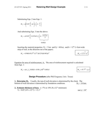
![CE 437/537, Spring 2011 Retaining Wall Design Example 1/8
Design a reinforced concrete retaining wall for the
psf
following conditions. surcharge = qs = 400
f'c = 3000 psi
Fill: φ = 32o
fy = 60 ksi Unit wt = 100 pcf
HT = 18 ft
tf
wtoe tstem wheel
Natural Soil: φ = 32o
allowable bearing pressure = 5000psf
Development of Structural Design Equations. In this example, the structural design of the
three retaining wall components is performed by hand. Two equations are developed in this
section for determining the thickness & reinforcement required to resist the bending moment
in the retaining wall components (stem, toe and heel).
Equation to calculate effective depth, d: Three basic equations will be used to develop an
equation for d.
M u = φM n
⎛ a⎞
M n = As f y ⎜ d − ⎟
⎝ 2⎠
⎛ a⎞
M u = φAs f y ⎜ d − ⎟ [ Eqn 1]
⎝ 2⎠
C = T , 0.85 f c' a b = As f y
f c'
As = 0.85 ab [ Eqn 2]
fy
0.003 ε s + 0.003 a 0.003
strain compatibility : = , = β1
a / β1 d d ε s + 0.003
Assuming β1 = 0.85,
εs a/d
0.005 0.319
0.00785 0.235
0.010 0.196
and choosing a value for εs in about the middle of the practical design range,
a
= 0.235, a = 0.235 d [ Eqn 3]
d](https://image.slidesharecdn.com/retainingwalldesignexample-121023234028-phpapp01/85/Retaining-wall-design_example-1-320.jpg)
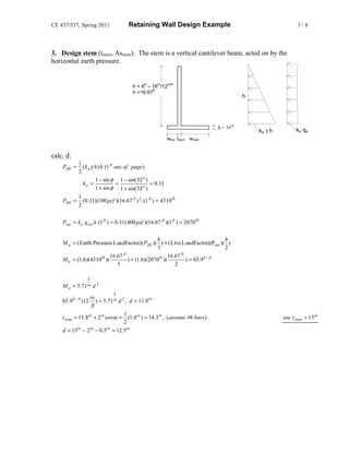
![CE 437/537, Spring 2011 Retaining Wall Design Example 1/8
Design a reinforced concrete retaining wall for the
psf
following conditions. surcharge = qs = 400
f'c = 3000 psi
Fill: φ = 32o
fy = 60 ksi Unit wt = 100 pcf
HT = 18 ft
tf
wtoe tstem wheel
Natural Soil: φ = 32o
allowable bearing pressure = 5000psf
Development of Structural Design Equations. In this example, the structural design of the
three retaining wall components is performed by hand. Two equations are developed in this
section for determining the thickness & reinforcement required to resist the bending moment
in the retaining wall components (stem, toe and heel).
Equation to calculate effective depth, d: Three basic equations will be used to develop an
equation for d.
M u = φM n
⎛ a⎞
M n = As f y ⎜ d − ⎟
⎝ 2⎠
⎛ a⎞
M u = φAs f y ⎜ d − ⎟ [ Eqn 1]
⎝ 2⎠
C = T , 0.85 f c' a b = As f y
f c'
As = 0.85 ab [ Eqn 2]
fy
0.003 ε s + 0.003 a 0.003
strain compatibility : = , = β1
a / β1 d d ε s + 0.003
Assuming β1 = 0.85,
εs a/d
0.005 0.319
0.00785 0.235
0.010 0.196
and choosing a value for εs in about the middle of the practical design range,
a
= 0.235, a = 0.235 d [ Eqn 3]
d](https://image.slidesharecdn.com/retainingwalldesignexample-121023234028-phpapp01/75/Retaining-wall-design_example-1-2048.jpg)
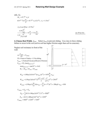
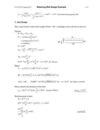
![CE 437/537, Spring 2011 Retaining Wall Design Example 7/8
8. Toe Design.
Earth Pressure at Tip of Toe:
Wu Mu
σv = ±
bL 1 2
bL
6
Wu = 1.2(W fill + Wstem + W found ) + 1.6 (Wsur )
Wu = 1.2(12.53k + 2.81k + 2.35k ) + 1.6(0.4 ksf )(18 ft )(1 ft ) = 32.7 k , (did not recalc foundation wt b.c. neglible change)
M u = 1.6 M over − 1.2(Wsoil × 2.125 ft + Wstem × 1.0 ft ) 3' 1.25' 7.5'
[ ]
M u = 1.6(50.2 k − ft ) − 1.2 12.53k ( 2.125 ft ) + 2.81k (1 ft ) = 45.0k − ft
32.7 k 45.0k − ft
σv = +
(1 ft )(11.75 ft ) 1 (1 ft )(11.75 ft ) 2
6
ksf
σ vA = 2.78 + 1.96ksf = 4.74 ksf
A B C
σ vC = 2.78ksf − 1.96ksf = 0.82 ksf
4.74 ksf − 0.82 ksf
σ vB = 0.82 ksf + (8.75 ft ) = 3.74 ksf
11.75 ft
d for flexure:
3 ft 1 2
M u = (3.74 ksf )(3 ft )(1 ft )( ) + (1.00 ksf )(3 ft )(1 ft )( 3 ft ) = 19.8k − ft
2 2 3
k 2
M u = 5.71 d
in
in k
19.8k − ft (12 ) = 5.71 d 2 , d = 6.5in for flexure
ft in
d for shear:
Assume theel = ttoe = 21.5in
Critical section for shear occurs at "d" from face of stem, d = 21.5" – 3"cover-1/2"=18"
4.74 ksf − 0.82 ksf 18
σ vcritical sec tion = 0.82 ksf + ft
(8.75 ft + ft ) = 4.24 ksf
11.75 12
1 18
Vu = ( 4.74 ksf + 4.24 ksf )(3 ft − ft )(1 ft ) = 6.74 k
2 12
φVc = (.75)2 3000 psi (12in )(18in ) = 17,750lb > Vu , OK , d for flexure controls](https://image.slidesharecdn.com/retainingwalldesignexample-121023234028-phpapp01/85/Retaining-wall-design_example-7-320.jpg)


![Geotechnical Engineering-II [Lec #25: Coulomb EP Theory - Numericals]](https://cdn.slidesharecdn.com/ss_thumbnails/25-181123050611-thumbnail.jpg?width=640&height=640&fit=bounds)


