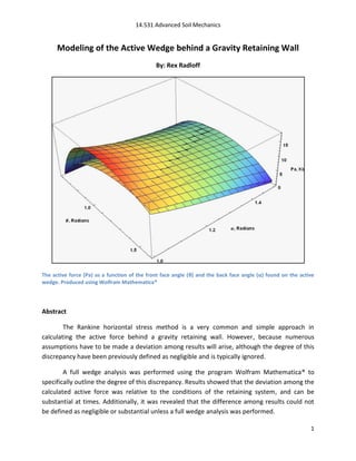
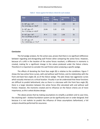
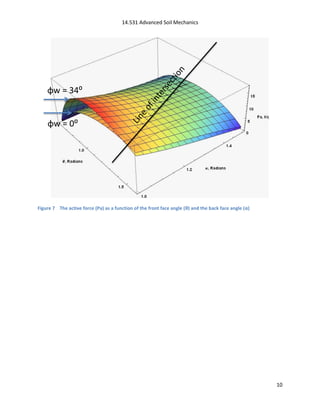
The document analyzes the active force behind a gravity retaining wall using both the Rankine horizontal stress method and a full wedge analysis in Mathematica. Two cases were examined. Results showed that while the calculated active forces were sometimes close, differences in the back face angle could create significant changes in failure criteria like sliding safety factor and bearing stress. A full analysis is needed because assumptions in the Rankine method may over or under design the wall depending on conditions. Deviating the front face angle more also increased differences between analyses with and without wall friction assumptions. The full analysis is important for accurate design.
This document discusses earth pressure theories and concepts. It explains the three types of earth pressures: active, passive, and at rest. Active pressure occurs when a retaining wall moves away from backfill, passive when it moves towards backfill, and at rest when stationary. Rankine and Coulomb theories are described, with Coulomb accounting for friction between the wall and soil. Graphical methods like Rebhann's and Culmann's are also summarized for determining failure surfaces and pressure distributions.
1. The bearing capacity of a foundation refers to the ability of the soil to carry the loads from structures placed on it without shear failure or excessive settlement.
2. Terzaghi's bearing capacity theory separates the failure zone under a foundation into triangular and radial shear zones, and considers the equilibrium of forces within these zones to calculate the ultimate bearing capacity.
3. The allowable bearing capacity is calculated by applying a safety factor to the ultimate capacity to avoid shear failure. Settlement criteria may further limit the allowable capacity.
Geotechnical Engineering-II [Lec #25: Coulomb EP Theory - Numericals]Muhammad Irfan
Class notes of Geotechnical Engineering course I used to teach at UET Lahore. Feel free to download the slide show.
Anyone looking to modify these files and use them for their own teaching purposes can contact me directly to get hold of editable version.
This document discusses lateral earth pressure on retaining walls. It introduces Rankine's and Coulomb's theories for estimating active and passive earth pressures. Rankine proposed that a semi-infinite mass of soil could reach states of plastic equilibrium under horizontal stretching (active state) or compression (passive state). Mohr circles are used to determine the principal stresses and orientation of potential failure planes for each state. The active pressure coefficient KA is related to the friction angle, while the passive pressure coefficient KP is also a function of friction angle.
Active Wedge Behind A Gravity Retaining Wall Complete 2011RexRadloff
This document models the active wedge behind a gravity retaining wall and examines how varying the wall geometry and soil friction parameters affect the active force and failure conditions. It presents two example retaining wall cases where adjusting the front face angle θ and considering/neglecting wall friction φw significantly increases the active force Pa and reduces safety against overturning or excessive eccentricity. The conclusion is that the active force depends jointly on θ, the back face angle α, and φw, so these parameters must be carefully determined when analyzing retaining wall stability.
TERZAGHI’S BEARING CAPACITY THEORY
DERIVATION OF EQUATION TERZAGHI’S BEARING CAPACITY THEORY
TERZAGHI’S BEARING CAPACITY FACTORS
Download vedio link
https://youtu.be/imy61hU0_yo
This document discusses stress distribution in soil due to various types of loading. It begins by introducing key concepts like how applied loads are transferred through the soil mass, creating stresses that decrease in magnitude but increase in area with depth. The factors that affect stress distribution, like loading size/shape, soil type, and footing rigidity are also covered. The document then examines specific load types - point loads, line loads, rectangular/triangular strip loads, and circular loads - providing the equations to calculate vertical stress increases below each. Several examples demonstrate calculating stress increases below compound load arrangements. The summary provides an overview of the key topics and calculations presented in the document.
This document discusses correlations between various geotechnical properties and the void ratio of soils. It defines void ratio as the ratio of volume of voids to volume of solids. Typical void ratio ranges are provided for different soil types. Relationships are presented between void ratio and properties such as unit weight, moisture content, maximum and minimum void ratios, relative density, shear modulus, hydraulic conductivity, preconsolidation pressure, and compression index. Graphs illustrate how properties such as shear strength and hydraulic conductivity vary with changes in void ratio.
This document provides a summary of the contents of a book titled "Basics of Foundation Design" by Bengt H. Fellenius. The book covers topics such as soil classification, cone penetration testing, settlement calculation, use of vertical drains to accelerate settlement, earth stress, bearing capacity of shallow foundations, static analysis of pile load transfer, analysis of static loading tests, pile dynamics, working stress design and load resistance factor design, specifications, examples, problems, and references. The book is intended as a background for conventional foundation analysis and design rather than replacing comprehensive foundation engineering textbooks. It originated from the author's foundation design course materials and as a background document for foundation design software.
Class notes of Geotechnical Engineering course I used to teach at UET Lahore. Feel free to download the slide show.
Anyone looking to modify these files and use them for their own teaching purposes can contact me directly to get hold of editable version.
1. This document provides information about vertical stresses below applied loads on the ground surface. It discusses theories of elasticity and how soils can be treated as quasi-elastic materials under limited loading conditions.
2. It presents Boussinesq's formula and Westergaard's modified formula for calculating vertical stresses below a point load on the ground surface. It also discusses pressure isobars and how they can be used to determine a significant depth below applied loads.
3. The document concludes with examples of calculating vertical stresses using Boussinesq's and Westergaard's formulas, and an example of determining pressure isobars and significant depth. Homework assignments are also provided applying the stress calculation methods.
This document discusses bearing capacity of shallow foundations. It defines bearing capacity as the ability of soil to safely carry pressure without shear failure. Terzaghi's bearing capacity theory from 1943 is described, including his assumptions of three soil zones and equations for calculating ultimate bearing capacity. The effects of foundation shape, inclined loads, soil type (clay vs. sand), and water table are explained. Settlement analysis is also important to determine allowable bearing capacity. An example problem demonstrates calculating the net allowable bearing capacity of a footing in clay.
The document discusses soil strength and different methods for measuring it. The Mohr-Coulomb failure criterion describes soil strength in terms of effective stresses. Laboratory tests like shear box and triaxial tests are used to measure soil strength parameters. The triaxial test can measure both drained (effective) and undrained strengths under controlled stress conditions. Interpretation of test results requires using concepts like effective and total stress Mohr circles.
1. The standard penetration test (SPT) involves driving a split-spoon sampler into the ground using a 63.5 kg hammer dropped from a height of 0.76 m. The number of blows required to drive the sampler over two intervals of 150 mm each is recorded as the SPT N-value.
2. The SPT N-value provides an approximate measure of soil resistance and a disturbed soil sample. It can be used to estimate soil strength parameters and bearing capacity through empirical correlations.
3. However, the SPT is highly dependent on the equipment and operator used, as factors like hammer efficiency, drill rod length, and borehole diameter can affect the N-value. Corrections are required
1. Load-settlement curves for footings on dense sand or stiff clay show a pronounced peak and failure occurs at very small strains, with sudden sinking or tilting and surface heaving of adjoining soil.
2. For medium sand or clay, failure starts at a localized spot and migrates outward gradually, with large vertical strains and small lateral strains. Failure planes are not clearly defined.
3. Failure zones for footings on slopes do not extend above the horizontal plane through the base, and failure occurs when downward and upward pressures are equal.
Class notes of Geotechnical Engineering course I used to teach at UET Lahore. Feel free to download the slide show.
Anyone looking to modify these files and use them for their own teaching purposes can contact me directly to get hold of editable version.
Class notes of Geotechnical Engineering course I used to teach at UET Lahore. Feel free to download the slide show.
Anyone looking to modify these files and use them for their own teaching purposes can contact me directly to get hold of editable version.
This document provides definitions and concepts related to bearing capacity of soil. It discusses Terzaghi's bearing capacity theory, which presents an equation for ultimate bearing capacity based on soil properties and footing geometry. The theory makes assumptions about soil behavior and failure mechanisms. Modifying factors are discussed for shape of footing, local shear failure, water table level, and eccentric loading conditions. A factor of safety of 3 is typically assumed unless otherwise.
The document describes the standard penetration test (SPT) method for determining the bearing capacity of soils. SPT involves driving a split spoon sampler into the soil using a 63.5 kg hammer dropped from a height of 75 cm. The number of blows required to penetrate each 150 mm interval is recorded as the N-value. N-values are corrected for overburden pressure and dilatancy. Bearing capacity is then calculated using corrected N-values, soil properties like internal friction angle, and factors for shape, depth, inclination, and water table location. The SPT provides soil strength data and undisturbed samples needed to determine cohesion and friction angle for bearing capacity calculations.
This document provides information about bearing capacity of soil and different types of foundations. It discusses key topics like:
- Types of foundations including shallow foundations like spread footings, continuous footings, combined footings, strap footings, and mat/raft foundations. It also discusses deep foundations.
- Factors that determine the selection of a foundation type including the structure's function/loads, sub-surface soil conditions, and cost.
- Comparison of shallow and deep foundations in terms of depth, load distribution, construction, cost, structural design considerations, and settlement.
- Criteria for foundation design including safety against bearing capacity failure and limiting settlement, especially differential settlement.
Skempton's analysis provides an improved method over Terzaghi's equation for determining the bearing capacity of cohesive soils. For footing depths less than 2.5 times the base width, Skempton showed that the bearing capacity factors in Terzaghi's equation increase with depth. For deeper footings, Skempton provided an alternative equation to calculate the bearing capacity factor for rectangular footings. The ultimate bearing capacity of cohesive soils can then be determined using the cohesion value.
liquefaction, its causes,mechanism and liquefaction potential mappings. Liquefaction analysis and measure of mitigation . along with susceptibility map of Kathmandu valley, Nepal and conclusion.
Geotechnical Engineering-II [Lec #20: WT effect on Bearing Capcity)Muhammad Irfan
Class notes of Geotechnical Engineering course I used to teach at UET Lahore. Feel free to download the slide show.
Anyone looking to modify these files and use them for their own teaching purposes can contact me directly to get hold of editable version.
This chapter discusses Terzaghi's bearing capacity theory for determining the ultimate bearing capacity of shallow foundations. It summarizes the key assumptions of Terzaghi's theory, including homogeneous, isotropic soil; two-dimensional problem; general shear failure; and vertical, symmetrical loading. It describes the failure mechanism with three zones - an elastic central zone beneath the footing, and two radial shear zones on the sides that meet the ground surface at angles of 45° - φ/2. Terzaghi's theory uses a semi-empirical equation to calculate ultimate bearing capacity based on soil properties of cohesion, friction, and the effective overburden pressure at the foundation level.
Bearing capacity of shallow foundations by abhishek sharma ABHISHEK SHARMA
elements you should know about bearing capacity of shallow foundations are included in it. various indian standards are also used. Bearing capacity theories by various researchers are also included. numericals from GATE CE and ESE CE are also included.
Class notes of Geotechnical Engineering course I used to teach at UET Lahore. Feel free to download the slide show.
Anyone looking to modify these files and use them for their own teaching purposes can contact me directly to get hold of editable version.
Pile foundations are commonly used when soil conditions require deep foundations, such as with compressible, waterlogged, or deep soils. There are various types of piles classified by function (e.g. end bearing, friction, tension), material (e.g. concrete, timber, steel), and installation method (e.g. driven, cast-in-place). The load carrying capacity of piles can be determined through dynamic formulas, static formulas, load tests, or penetration tests. Factors like pile length, structure characteristics, material availability, loading types, and costs must be considered for proper pile selection.
The document discusses various types of retaining walls and their failure modes. It describes gravity, semi-gravity, cantilever, counterfort, and buttress retaining walls. The five modes of failure are identified as sliding, overturning, bearing capacity, shallow shear, and deep shear failures. Factors of safety are provided for each failure mode. Two case studies of retaining wall collapses are also summarized.
This document describes cantilever retaining walls. It defines a retaining wall as a structure that maintains ground surfaces at different elevations on either side. Cantilever retaining walls consist of a stem supported by a base and resist lateral forces through bending. The document discusses the types of forces acting on retaining walls, methods for calculating lateral earth pressures, and design considerations for stability, soil pressure distribution, and reinforcement in the stem, toe slab, and heel slab.
Retaining walls are designed to retain soil at an angle greater than its natural slope, usually in a near-vertical position. They work by either their own mass or through leverage to prevent overturning, sliding, or soil overload. Design considerations include the subsoil type and water table level, as they can impact bearing capacity and hydrostatic pressure. Common wall types are gravity, cantilever, counterfort, precast concrete, and precast crib walls. Proper design is needed to ensure stability based on the wall height, materials, and subsurface conditions.
OPTIMUM DESIGN OF SEMI-GRAVITY RETAINING WALL SUBJECTED TO STATIC AND SEISMIC...IAEME Publication
A 2D (Plain strain) wall‒backfill‒foundation interaction is modeled using finite element
method by ANSYS to find the optimum design based on the principle of soil-structure
interactions analyses. A semi-gravity retaining wall subjected to static and seismic loads has
been considered in this research. Seismic records which are obtained from the records of Iraq
for the period 1900-1988. The optimization process is simulated by ANSYS /APDL language
programming depending on the available optimization commands. The objective function of
optimization process OBJ is to minimize the cross-sectional area of the retaining wall. The
results showed that the optimum design method via ANSYS is a successful strategy prompts to
optimum values of cross‒sectional area with both safety and stability factors as compared with
other optimum design methods. Also, the results showed that the area of optimum section by
ANSYS method is lesser than the section area of the GAs algorithm , PSO, and CSS methods by
percentages are equal to 15.04%, 23.92%, and 25.33%; respectively, when
3.Additionally, from studying the effect of some parameters such as Compressive Strength of
Concrete (´
) and Yielding Strength of Steel ( on cross-sectional area and reinforced
area, is provided that the (´) and have small effect or do not effect on the value of crosssectional
area () and this is due to the lack of weight ratio of steel reinforcement to concrete
weight. Moreover, the yielding strength of steel has larger effect than compressive strength of
concrete in the reinforcement area.
This document discusses different types of retaining walls, including:
- Gravity walls, pre-cast crib walls, gabion walls, reinforced concrete walls, sheet pile walls, mechanically stabilized earth (MSE) walls, slurry walls, secant pile walls, soldier piles and lagging walls, cofferdam walls, and hybrid systems.
It provides details on the materials, designs, and uses of various retaining wall types. Common materials include wood, steel, concrete, and soil reinforcements. Walls are chosen based on factors like height, site conditions, costs, and whether they are temporary or permanent.
This document discusses lateral earth pressure theories for retaining walls. It describes three common types of retaining walls: gravity walls, cantilever walls, and counter fort walls. It then explains Rankine and Coulomb earth pressure theories, focusing on Rankine's theory that lateral pressure varies linearly with depth and the resultant pressure is one-third the height above the base. The document also addresses factors that affect lateral pressure, such as uniform surcharge, submerged backfill, stratified backfill, inclined surcharge, sloping backfill, and inclined wall backs.
This document discusses different types of retaining walls and their design considerations. It describes:
1. Gravity, cantilever, counterfort, and buttress retaining wall types based on their structural components and typical height ranges.
2. Design considerations for retaining walls including stability against overturning, sliding, and settlement; drainage; and structural design basis using load and safety factors.
3. An example problem showing calculations for earth pressure, restoring moments, and checking stability of a gravity wall.
Retaining walls are structures used to retain soil or rock in a vertical position. Common materials used include wood, steel, concrete, and gabions. Retaining walls are classified as externally or internally stabilized. Externally stabilized include in-situ and gravity walls. Internally stabilized include reinforced soils and in-site reinforcement. Design considerations include ensuring stability against overturning, sliding, and overloading soils. Design also accounts for active and passive earth pressures. Common gravity wall types are massive gravity, crib, and cantilever walls. In-situ walls include sheet pile, soldier pile, and slurry walls. Reinforced and geosynthetic retaining walls are advanced wall types.
This document discusses lateral earth pressure and its importance in retaining wall design. It defines lateral earth pressure as the pressure soil exerts horizontally. Lateral earth pressure depends on soil shear strength, pore water pressure, and equilibrium state. It is important for designing structures like retaining walls, bridges, and tunnels. The document discusses coefficient of lateral earth pressure (K), and the three states: at-rest (Ko), active (Ka), and passive (Kp) pressure. It also presents Coulomb and Rankine theories for calculating earth pressure and describes investigation methods and lateral wall supports like gravity, cantilever, anchored, soil-nailed, and reinforced walls. Geofoam is discussed as a method to reduce lateral stresses in
Retaining walls are used to retain earth in a vertical position where there is an abrupt change in ground level. There are several types of retaining walls including gravity, cantilever, counterfort, and buttress walls. Cantilever walls are the most common type for heights up to 8 meters. They consist of a vertical stem and base slab that behave like one-way cantilevers. Counterfort walls include transverse supports called counterforts to reduce bending moments in the stem and slabs. Proper design of the stem, heel slab, toe slab, and foundation depth is required to resist overturning, sliding, soil pressure, and bending failure.
This document discusses different types of retaining walls, including gravity, cantilevered, counter fort, precast concrete, and sheet pile walls. It describes factors that influence retaining wall design such as soil type, water table height, and subsurface water movement. The key forces that act on retaining walls are also examined: pressure at rest, active earth pressure, and passive earth pressure. Finally, five common modes of retaining wall failure are identified: sliding, overturning, bearing capacity, shallow shear, and deep shear failures.
This document is Douglas Olaf Carlson's 1995 PhD dissertation at Michigan State University titled "Physics of Single-Top Quark Production at Hadron Colliders". It discusses several topics related to producing and measuring properties of single top quarks at hadron colliders like the Tevatron and LHC. This includes calculating production rates for various single top processes, methods for measuring the top quark mass and width, probing top quark couplings to the W boson, and exploring CP properties of the top quark. It also presents a Monte Carlo study on detecting single top events and analyzing backgrounds at the Tevatron and LHC.
This document reviews research on the convergence of perturbation series in quantum field theory. It discusses Dyson's argument that perturbation series in quantum electrodynamics (QED) have zero radius of convergence due to vacuum instability when the coupling constant is negative. Large-order estimates show that perturbation series coefficients grow factorially fast in quantum mechanics and field theories. Finally, it describes the method of Borel summation, which may allow extracting the exact physical quantity from a divergent perturbation series through a unique mapping.
The document presents simplified procedures for seismic analysis and design of pile-supported wharves and piers in marine oil and LNG terminals. It proposes using a coefficient-based approach to estimate displacement demand for regular structures, and a modal pushover analysis for irregular structures. It also recommends expressions for estimating displacement ductility capacity of piles to determine if piles meet displacement limits rather than material strain limits. The procedures are intended to provide a simplified alternative to the more detailed nonlinear analysis methods currently specified.
This document is Scott Shermer's master's thesis on instantons and perturbation theory in the 1-D quantum mechanical quartic oscillator. It begins by reviewing the harmonic oscillator and perturbation theory. It then discusses non-perturbative phenomena like instantons and Borel resummation. The focus is on obtaining the ground state energy of the quartic oscillator Hamiltonian using both perturbative and non-perturbative techniques, and addressing ambiguities that arise for negative coupling.
This document summarizes a numerical study of airflow over an Ahmed body using RANS turbulence models. It finds that the k-ε-v2 model more accurately predicts separation and reattachment compared to other models. The study simulates flow over an Ahmed body with a 35 degree rear angle using various turbulence models and investigates the effects of grid layout and differencing schemes on the results. Numerical results agree well with experimental data on the wake structure and turbulent kinetic energy distribution behind the body.
This document outlines an approach to studying time correlations of conserved fields in anharmonic chains using nonlinear fluctuating hydrodynamics. It introduces the BS model, which has two conserved fields - displacement and potential energy. The dynamics of these fields can be approximated by a two-component stochastic Burgers equation. Classifying the universality classes of this equation's correlation functions allows insights into the original anharmonic chain model. Numerical results for specific potentials are also discussed.
This document provides an overview of experimental strain analysis techniques, specifically focusing on strain gages, photoelasticity, and moire methods. It describes how strain gages use changes in electrical resistance to measure strain, and how they are usually connected to a Wheatstone bridge circuit to improve measurement sensitivity. Photoelasticity and moire methods allow full-field displays of strain distributions by exploiting the birefringent properties of certain materials, in which refractive index depends on polarization orientation.
Taller grupal 2_aplicacion de la derivada en la ingeniera electrónica y autom...JHANDRYALCIVARGUAJAL
The document is a report in Spanish for a Calculus course. It discusses applications of the derivative in the career of electronics and automation. It contains 3 problems solved using concepts of maxima, minima, and the first and second derivatives. The problems involve finding the maximum power output of a circuit, determining the maximum net resistance of a parallel circuit, and calculating the maximum error in the equivalent resistance of a parallel circuit based on measurement errors.
This document discusses the results of an investigation into splitting of timber dowel joints. It summarizes the following key points in 3 sentences:
The document critiques the empirical methods used in previous studies, arguing they do not fit theoretical models and have high variability. It then precisely fits the experimental data from one study to limit analysis theory, demonstrating a 10% coefficient of variation. The analysis shows the empirical data can be trusted but that exact theory, not empirical approaches, provides the proper design rules for timber dowel joints.
Applying Geo-mechanics to Well Modelling and Inflow Performance RelationshipsDaniel Chia
1) The document describes applying geo-mechanics principles to model sand production and inflow performance in wells. It presents an equation that projects the "sanding line" which indicates when sand will be produced onto the flow rate vs bottom hole pressure graph.
2) Key concepts discussed include the Mohr-Coulomb failure criterion for predicting rock failure, concepts of total, effective and minimum/maximum horizontal stresses, and how stresses change around deviated or perforated wellbores.
3) Two example applications are presented to illustrate using geo-mechanics to model inflow relationships and sand production for a well, though actual formation measurements are preferable to the assumed values used in the examples.
Estimation of Damping Derivative in Pitch of a Supersonic Delta Wing with Cur...iosrjce
In the Present paper effect of angle of incidence on Damping derivative of a delta wing with Curved
leading edges for attached shock case in Supersonic Flow has been studied. A Strip theory is used in which
strips at different span wise location are independent of each other. This combines with similitude to give a
piston theory which gives closed form solutions for damping derivatives at low to high supersonic Mach
numbers. From the results it is seen that with the increase in the Mach number, there is a progressive decrease
in the magnitude of damping derivatives for all the Mach numbers of the present studies; however, the decrease
in the magnitude is variable at different inertia level. It is seen that with the increase in the angle of attack the
damping derivative increases linearly, nevertheless, this linear behavior limit themselves for different Mach
numbers. For Mach number M = 2, this limiting value of validity is fifteen degrees, for Mach 2.5 & 3, it is
twenty five degrees, whereas, for Mach 3.5 & 4 it becomes thirty five degrees, when these stability derivatives
were considered at various pivot positions; namely at h = 0.0, 0.4, 0.6, and 1.0. After scanning the results it is
observed that with the shift of the pivot position from the leading edge to the trailing edge, the magnitude of the
damping derivatives continue to decrease throughout. Results have been obtained for supersonic flow of perfect
gases over a wide range of angle of attack and Mach number. The effect of real gas, leading edge bluntness of
the wing, shock motion, and secondary wave reflections are neglected.
HEATED WIND PARTICLE’S BEHAVIOURAL STUDY BY THE CONTINUOUS WAVELET TRANSFORM ...cscpconf
Nowadays Continuous Wavelet Transform (CWT) as well as Fractal analysis is generally used for the Signal and Image processing application purpose. Our current work extends the field of application in case of CWT as well as Fractal analysis by applying it in case of the agitated wind particle’s behavioral study. In this current work in case of the agitated wind particle, we have mathematically showed that the wind particle’s movement exhibits the “Uncorrelated” characteristics during the convectional flow of it. It is also demonstrated here by the Continuous Wavelet Transform (CWT) as well as the Fractal analysis with matlab 7.12 version
1. The chapter discusses momentum and forces in fluid flow, including the development of the momentum principle using Newton's second law and the impulse-momentum principle.
2. The momentum equation is developed for two-dimensional and three-dimensional flow through a control volume, accounting for forces, velocities, flow rates, and momentum correction factors.
3. Examples of applying the momentum equation are presented, including forces on bends, nozzles, jets, and vanes.
Introduction to back analysis;
Definition- Back analysis;
Historical Review- back analysis;
Factors affecting back analysis;
Steps to perform back analysis;
Solved numerical for demonstration of back analysis;
Practical Problems and limitations of back analysis;
Advantages of back analysis
How to make back analysis accurate?;
Concluding remarks;
Selected References; back analysis procedure;
Back analysis in slope stability problems
1) The bearing capacity of a shallow foundation is the maximum pressure it can support before failing. It depends on factors like the soil's strength properties, drainage conditions, foundation shape, and water table level.
2) Two common methods to analyze bearing capacity are the lower bound approach, which finds stresses that cause failure everywhere, and upper bound approach, which assumes a failure mechanism and calculates loads that cause it.
3) The general bearing capacity equation accounts for surcharge loads, soil weight, cohesion, and bearing capacity factors that depend on the soil's friction angle.
4) Short-term undrained and long-term drained analyses consider total and effective stresses, using saturated unit weight and water levels appropriately
This document describes the implementation of an Extended Kalman Filter (EKF) to estimate the state (position and heading angle) of a bicycle model. The EKF was able to provide reasonably accurate estimates of position over time based on position measurements and steering/velocity inputs, but struggled to accurately estimate the heading angle due to a lack of direct measurements. Histograms of the final state errors across many test cases showed normally distributed position errors and a uniformly distributed random heading angle error. While the EKF provided an approximation, a more advanced filter may have yielded better heading angle estimates.
Multi-Fidelity Optimization of a High Speed, Foil-Assisted Catamaran for Low ...Kellen Betts
This document discusses a multi-fidelity optimization of a high-speed, foil-assisted catamaran design for low wake in Puget Sound. It describes the motivation and objectives to reduce vessel wake through hull geometry optimization and lifting surfaces. It outlines the computational models, including a low-fidelity potential flow model and high-fidelity URANS model. It also discusses the multi-objective global optimization approach, including parameterization methods, interpolation methods, and optimization algorithms. The document notes that results will include the final optimized design and sea trial validation.
Similar to Modeling of the Active Wedge behind a Gravity Retaining Wall (20)
Multi-Fidelity Optimization of a High Speed, Foil-Assisted Catamaran for Low ...
Modeling of the Active Wedge behind a Gravity Retaining Wall
1. 14.531 Advanced Soil Mechanics
Modeling of the Active Wedge behind a Gravity Retaining Wall
By: Rex Radloff
The active force (Pa) as a function of the front face angle (θ) and the back face angle (α) found on the active
wedge. Produced using Wolfram Mathematica®
Abstract
The Rankine horizontal stress method is a very common and simple approach in
calculating the active force behind a gravity retaining wall. However, because numerous
assumptions have to be made a deviation among results will arise, although the degree of this
discrepancy have been previously defined as negligible and is typically ignored.
A full wedge analysis was performed using the program Wolfram Mathematica® to
specifically outline the degree of this discrepancy. Results showed that the deviation among the
calculated active force was relative to the conditions of the retaining system, and can be
substantial at times. Additionally, it was revealed that the difference among results could not
be defined as negligible or substantial unless a full wedge analysis was performed.
1
3. 14.531 Advanced Soil Mechanics
Introduction
As an engineer it is important to accurately produce results in a short amount of time.
Producing incorrect results quickly is unacceptable as the same goes for producing the correct
result over an extended period of time. It is common practice for an engineer to minimize time
by making assumptions and producing results that are within the range of error. However, if
this practice is fully adopted, then there may be times when an assumption can be at the
expense of an accurate result. The following will attempt to place the degree of significance of
putting more time into improving the results calculated from the Rankine method when
analyzing a retaining wall, and determining frankly, “is it worth it?”
Rankine Active Wedge
The Rankine horizontal stress method is a very common and simple approach in
calculating the active force behind a gravity retaining wall. The assumptions associated with this
method is that the wall friction is φw = 0:, front face of the wedge is θ = 90:, back face of the
wedge is α = 45 + φ/2, overburden grade is β = 0:, and the resultant of the active force acts at a
distance of H/3 from the base. Figures 1 and 2 demonstrate these constraints by showing the
geometry of the driving wedge and stress distribution behind the retaining wall.
However, again, this analysis represents the case with all of the above assumptions and
there is no way of knowing if these conditions are those that produce the highest active force.
Therefore, a full wedge analysis will need to be performed while these variables are free to
deviate, and the conditions which produce the largest active force should be compared with
those from the above method. It is important to stress that it is not the difference between
each calculated active force that is of concern, rather the difference of produced moment on
the foundation, which is a function of the resultants location.
Figure 1 Geometry of the driving wedge under the Rankine active wedge analysis.
3
4. 14.531 Advanced Soil Mechanics
Figure 2 Stress distribution of the active pressure behind a gravity retaining wall using the Rankine horizontal
active stress parameter Ka.
Wedge Analysis
To perform an accurate wedge analysis behind a gravity retaining wall, Figure 3 must be
considered in its entirety. The known variables are as follows: wall dimensions and materials,
soil and wall shear strength parameters, and the grade of the overburden soil. The variables to
be solved for, at the maximum active force, is the angle of the front face (θ), the angle of the
back face (α), and location of the active force. To model such a problem, it is preferred to use a
modeling program such as Wolfram Mathematica® to plot and interpret data.
Figure 3 Active wedge with consideration towards θ, β, and φw
4
5. 14.531 Advanced Soil Mechanics
Case 1 (θ = 72⁰ 90⁰, φw = 34⁰)
The example which will be interpreted for comparison purpose can be seen in Figure 4.
The analysis will consider the blue and red wedge with and without wall friction (φw). The
example did limit the overburden grade (β) to 0: in hopes to recognize any deviation specifically
related to the Rankine method. Also the maximum angle (θ) of the front face of the wedge in
red is controlled by the wall dimensions.
Figure 4 Example 1 for an active wedge analysis
Results: Case 1 (θ = 72⁰ 90⁰, φw = 34⁰)
The data from case 1 was analyzed using Wolfram Mathematica and can been seen in
Figure 5. The active force (Pa) and angle of the back face (α) of the blue wedge (θ = 90:) are
6.51 Kips and 56.8: for the analysis with wall friction, and 7.12 Kips and 62.0: for the analysis
without wall friction. It should be noted that α = 62.0: is also equal to 45 + φw/2. The results
yielded are fairly close to one another; however the differences in moments still need to be
interpreted to actually understand its influence on the design.
The active force (Pa) and angle of the back face (α) of the red wedge (θ = 71:) are 11.24
Kips and 61.2: for the analysis with wall friction, and 10.84 Kips and 71.2: for the analysis
without wall friction. The active forces calculated are fairly close to one another; however the
angles of the back face (α) deviate by 10:. This is especially important, as an engineer uses the
location of the failure in certain types of retaining wall design, i.e. using tiebacks, soil nails, or
dead-man anchors.
5
6. 14.531 Advanced Soil Mechanics
Figure 5 Wedge analysis using the following: γ = 117 pcf, Cs = 0 psf, Cw = 0 psf, H = 20.75 ft, Wh = 6.00 ft, φ =
34⁰, β = 0⁰
Between both sets of values, the calculated active force (Pa) and angle of the back face
(α) deviate significantly from one another. These results show an underestimation of the active
force by a factor of 1.7. With that said, this does not mean the foundation was under designed
by the same factor; there still needs to be an analysis done on the retaining walls failure
criteria, which takes into consideration the location of each resultant.
Failure Criteria: Case 1 (θ = 72⁰ 90⁰, φw = 34⁰)
The failure criteria of a retaining wall – shallow foundation system consists of
overturning, sliding, eccentricity, and bearing capacity, and any deviation in the above results
will only be considered depending on their effects on this criteria. Table 1 present this failure
criteria for each case.
For the analysis of the blue wedge (θ = 90:), the failure criteria deviated by a factor 1.4
and 1.7 for the factor of safety against sliding and the maximum bearing stress respectively.
This hints that the resultant shifted enough to create a large enough difference in moments and
also verifies the significance of the wall friction, regardless of the similar active forces. For the
analysis of the red wedge (θ = 71:), the failure criteria deviated by 1.6 and 1.9 for the factor of
safety against sliding and the maximum bearing stress respectively.
6
7. 14.531 Advanced Soil Mechanics
Table 1 Values against the failure criteria for each analysis
Case FS Over- FS Eccentricity q
MAX
Turning Sliding (ft) (ksf)
θ = 90:, φw = 34:, 3.53 3.47 -1.45 31
Pa = 6.51 Kips, α = 56.8:
θ = 90:, φw = 0:, 3.69 2.46 0.53 18
Pa = 7.12 Kips, α = 62.0:
θ = 71:, φw = 34:, 0.53 2.68 -0.04 17
Pa = 11.24 Kips, α =61.2:
θ = 71:, φw = 0:, 0.85 1.61 3.48 32
Pa = 10.84 Kips, α = 71.2:
However, the two wedges of interest are the blue (θ = 90:) and the red (θ = 71:), as they
represent the two extremes between making and not making assumptions. The values
presented in Table 1 show a deviation by a factor of 7.0 for the factor of safety against
overturning; the remaining values are close enough to ignore any difference. Nevertheless, the
difference in the factor of safety against overturning is enough to consider the two methods.
Case 2 (θ = 45⁰ 90⁰, φw = 34⁰)
The second case that will be interpreted under the wedge analysis can be seen in Figure
5. The purpose of this example is to understand if there is any validity to the above results,
which can be determined by extending the front face angle (θ) to an extreme case and monitor
how each result varies. The blue wedge will represent the Rankine case being interpreted with
and without wall friction (as analyzed before) and the red wedge will represent the extreme
case with the front face angle (θ) equal to 0, with and without wall friction.
Figure 5 Example 2 for an active wedge analysis
7
8. 14.531 Advanced Soil Mechanics
Results: Case 2 (θ = 45⁰ 90⁰, φw = 34⁰)
The data from case 2 was analyzed using Wolfram Mathematica and can been see in
Figure 6. The active force (Pa) and angle of the back face (α) of the red wedge (θ = 45:) are
29.03 Kips and 62.0: for the analysis with wall friction, and 21.41 Kips and 84.5: for the analysis
without wall friction. The active forces calculated now begin to separate much more than
before, as does the difference in the angle (α) of the wedges back face. Also, the active force
and angle of the back face found under the blue wedge (θ = 45:) are the same from the
previous example.
Figure 6 Wedge analysis using the following: γ = 117 pcf, Cs = 0 psf, Cw = 0 psf, H = 20.75 ft, Wh = 6.00 ft, φ =
34⁰, β = 0⁰
Failure Criteria: Case 2 (θ = 45⁰ 90⁰, φw = 34⁰)
The two wedges of interest are the Rankine wedge (blue, θ = 90:) without wall friction
and the red wedge (θ = 45:) with wall friction. Results from the failure criteria show a larger
deviation between each case, but more importantly the maximum bearing stress (q MAX)
deviates by a factor of 1.57. This proves that increasing the front face angle (θ) to a certain
degree will lead to a significant deviation between the maximum bearing stress. It should also
be noted that the overturning values approach infinity as the resultant of the active force
points below the point of rotation (pt. O).
8
9. 14.531 Advanced Soil Mechanics
Table 2 Values against the failure criteria for each analysis
Case FS Over- FS Eccentricity q
MAX
Turning Sliding (ft) (ksf)
θ = 90:, φw = 34:, 7.11 7.07 -1.93 50
Pa = 6.51 Kips, α = 56.8:
θ = 90:, φw = 0:, 15.04 5.19 0.70 35
Pa = 7.12 Kips, α = 62.0:
θ = 45:, φw = 34:, ∞ 7.23 -1.90 55
Pa = 11.24 Kips, α =61.2:
θ = 45:, φw = 0:, ∞ 2.36 2.66 42
Pa = 10.84 Kips, α = 71.2:
Conclusion
The full wedge analysis, for the active case, proves that there is no significant difference
between regarding and disregarding wall friction when comparing the active force. However,
because of a shift in the location of the active forces resultant, a difference in moments is
created, making for a significant change in the values produced under the failure criteria.
Therefore it is important to consider the wall friction when analyzing a specific wedge.
The effects of deviating the front face angle (θ) is relative to the conditions. Figure 7
shows the two active force curves, with and without wall friction, and its relationship with the
front and back face angles (θ, α) of the failure wedge. The plot shows two aggressive curves
which actually intersect at a critical location. Visually it can be understood that these functions
are difficult to predict beforehand; also as there is a decrease with the front face angle (θ),
there is a larger deviation between the active forces (Pa) calculated with and without wall
friction. However, the moments created and its influence on the failure criteria are of more
importance, as this is what dictates design.
The above proves that by making assumptions to simplify a problem and to save time,
the retaining wall – shallow foundation system can be significantly over or under designed. And
because it is not realistic to predict the influence of these assumptions beforehand, a full
analysis should be performed for assurance.
9
10. 14.531 Advanced Soil Mechanics
φw = 34:
φw = 0:
Figure 7 The active force (Pa) as a function of the front face angle (θ) and the back face angle (α)
10