Downloaded 24 times
![IJRET: International Journal of Research in Engineering and Technology eISSN: 2319-1163 | pISSN: 2321-7308
_______________________________________________________________________________________
Volume: 04 Issue: 04 | Apr-2015, Available @ http://www.ijret.org 447
OPTIMIZATION AND IMPROVEMENT IN STABILITY OF
COUNTERFORT RETAINING WALL WITH RELIEF SHELF
Tonne V. R1
, Mohite P. M2
1
M. Tech Scholar, Civil Engineering Department, R. I. T., Sangli, Maharashtra, India
2
Associate Professor of Civil Engineering Department, R. I. T., Sangli, Maharashtra, India
Abstract
Reinforced concrete retaining walls are meant to support more height of earth mass. Cantilever retaining wall is constructed up
to height of 6 m and above that it becomes uneconomical. To support more height of earth mass advancement is done in cantilever
retaining wall by adding relief shelf in it. Due to provision of relief shelf the soil pressure on the retaining wall is reduced
resulting in improvement in stability of retaining wall. Cantilever retaining wall with one relief shelf is economical up to height of
10 m above that counterfort retaining wall with relief shelf is useful. In this paper analysis and design of counterfort retaining
wall with one relief shelf is done for various positions of relief shelf. These results are studied to get minimum earth pressure,
more stability and minimum moment in each component of retaining wall. The optimization of counterfort retaining wall is done
to get minimum size of retaining wall. Due to this optimization extra formation width is available in hilly areas and excessive
cutting is avoided thereby construction cost reduces.
Keywords: Counterfort Retaining wall, relief shelf, earth pressure, Factor of safety, overturning, sliding, optimization
--------------------------------------------------------------------***----------------------------------------------------------------------
1. INTRODUCTION
Retaining structures are the walls meant to support earth or
other materials. In order to design retaining wall it is
necessary to determine active and passive earth pressures on
wall. In hills it is not possible to construct roads without
retaining structures. Retaining structures are encountered
and constructed in various fields of engineering such as
roads, harbors, dams, subways, railroads, tunnels mines and
military fortification.
According to Khural R. [2]
to achieve required formation
width and to stabilize disturbed hill slopes number of
retaining structures are constructed in hilly terrain, its
construction cost is near about 20% to 30 %of hill roads
project cost. Gravity retaining walls are designed by
considering its shape and size. Its stability is depending on
its dimensions. Design of gravity retaining wall is not based
on type of material used for construction. Ray Choudhari [1]
had concluded that when height of earth mass to be retained
is less than 6 m cantilever retaining wall is generally
preferred. Above 6 m height counterfort retaining wall is
used to achieve economy in construction. Cantilever
retaining wall with relief shelf is alternative to counterfort
retaining wall which is found out easy to construct and more
economic. As total active earth pressure on retaining wall
with relief shelf is lower in magnitude than that of
conventional type, keying at the base may not be necessary
to prevent sliding in certain cases. Patil S. [4]
says that by
providing relief shelf in cantilever retaining wall it is found
that factor of safety against overturning and sliding is
improved. Due to provision of relief shelf earth pressure
reduces which results in reduction in section. As section of
retaining wall is less, requirement of construction material is
also less which results reduction in cost. He had found that
reduction in volume of concrete and steel is 35 % and 18%
respectively. For height in the vicinity of 10 m cantilever
retaining wall with single relief shelf is economical than
conventional counterfort retaining wall but further economy
is achieved by providing relief shelf in counterfort.
2. COULOMB THEORY
The Coulomb‟s theory is conveniently adopted when the
plane of failure extending diagonally upward and backward
through the backfill. The sliding wedge is a triangular mass
of soil between this plane of failure and the back face of
retaining wall. The soil within the sliding wedge would
slump down when the retaining wall is suddenly removed. If
a plane of failure makes an angle ᴓ with the horizontal, the
forces acting on the sliding wedge are as shown in figure 1.
Forces acting on failure plane these forces consist of weight
of the soil within the wedge W which acts through the
centroid of the triangle, a thrust normal to the plane of
failure N which exerted by the soil to the right of the failure
plane. N = N tan ᴓ will be at the limit of equilibrium. These
forces must be balanced by the thrust P which is assumed to
act horizontally and to be concurrent with W, N and S. The
equal and opposite reaction to P is the lateral force to
withstand which the wall is to be designed. The forces N
and S may be replaced by the resultant R to derive the value
of P. S acts along a line making the angle ᴓ with the normal
to the failure plane. Since W, P and R are three concurrent
forces which are in equilibrium, when the failure is about to
take place along the failure plane, they may be represented
by the triangle of forces in figure 1. In this triangle P=W
tanρ-ᴓ=1/2*Ka*γ*H2](https://image.slidesharecdn.com/optimizationandimprovementinstabilityofcounterfortretainingwallwithreliefshelf-160903063648/75/Optimization-and-improvement-in-stability-of-counterfort-retaining-wall-with-relief-shelf-1-2048.jpg)
![IJRET: International Journal of Research in Engineering and Technology eISSN: 2319-1163 | pISSN: 2321-7308
_______________________________________________________________________________________
Volume: 04 Issue: 04 | Apr-2015, Available @ http://www.ijret.org 448
Fig.1 Forces acting on failure plane
Fig. 2 shows the active and passive state of plastic
equilibrium in a non-cohesive soil with the horizontal
ground surface. In an active state the major principal stress
σ1 is vertical and minor principal stress σ2 is horizontal.
Circle I represents such a state in which the pole P1
corresponds to minor principal stress while point A
corresponds to major principal stress The circle touches the
failure envelopes at F1 and F2‟ hence P1F1 and P1F1‟show
the directions of failure planes or slip lines these slip lines
also shown in fig. 2. Similarly direction of the major
principal stress and minor principal stresses are vice versa.
Fig.2 Active and Passive states of plastic equilibrium
3. LOFT THEORY
For non-cohesive soils the active earth pressure on a
retaining wall can be computed by considering the stabilities
of different wedges of soil mass. It attains a maximum value
when the rupture plane makes an angle of 45o
+ ᴓ/2 with the
horizontal, where ᴓ is the angle of internal friction of the
non-cohesive soil. Fig 3 shows cross section of retaining
wall with one horizontal shelf of width „b‟ and thickness „t‟
at a height „H-h‟ from the base. When b= H-T-h tan [45o
+
ᴓ/2], the rupture plane originating at the intersection of base
and stem on the backfill side meets the horizontal shelf.
According to Jumikies the earth pressure distribution
diagram below the shelf would be as shown in the fig.3, as if
a free surface existed at the shelf level. If b is greater than
H-T-h tan [45o
+ ᴓ/2], the rupture plane which gives the
maximum value of lateral earth pressure, i.e. the plane
inclined at 45o
+ ᴓ/2 with the horizontal, cannot develop, as
it has to go through the shelf. The total active earth pressure
at any level can be obtained by stability analysis of wedge,
assuming that by providing a horizontal shelf, the weight of
the earth over the shelf is born by the shelf and the weight of
this soil mass is not effective to cause sliding.
Fig.3 Cross section of retaining wall with one relief shelf
and soil pressure on wall
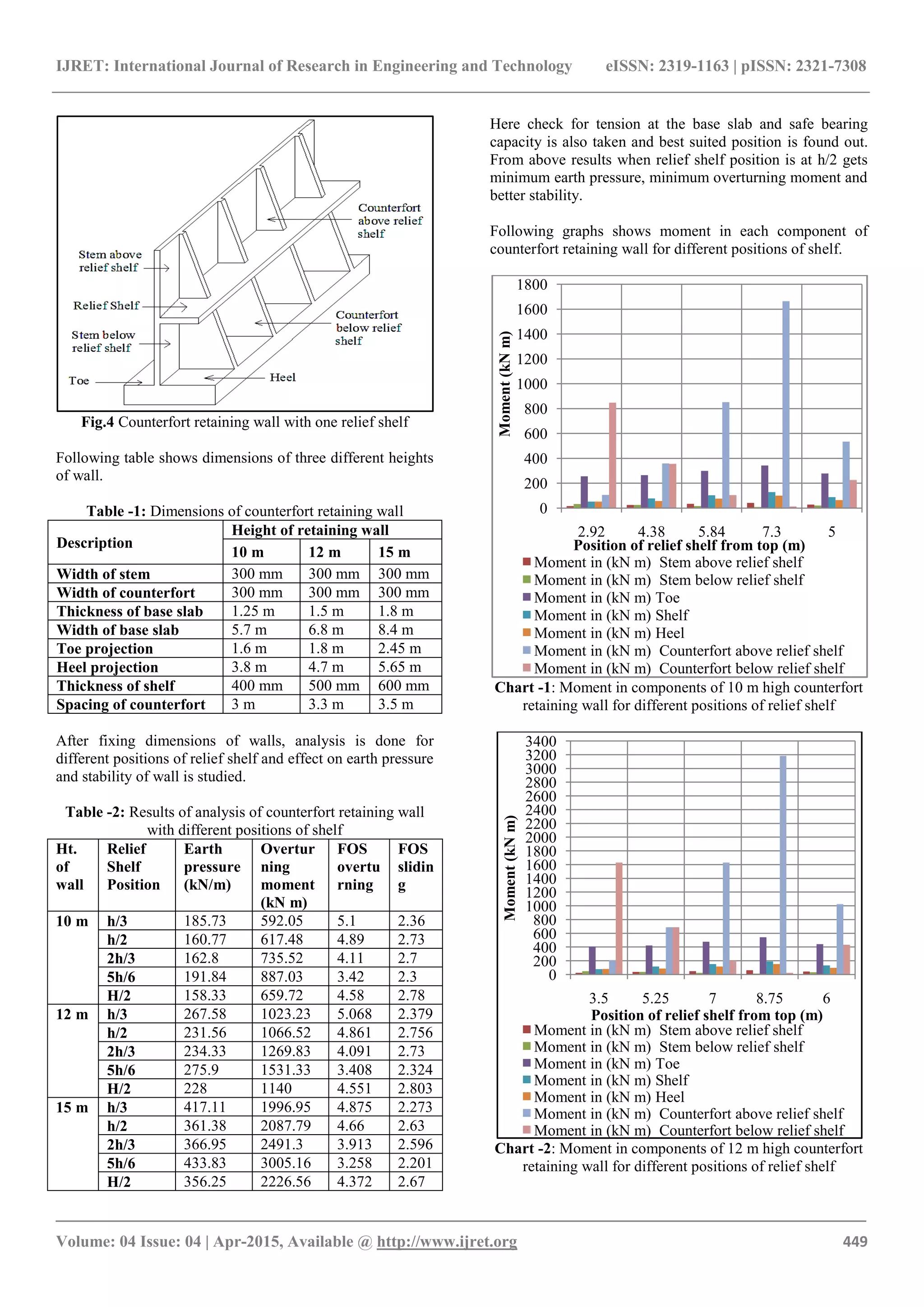
4. ANALYSIS OF COUNTERFORT RETAINING
WALL WITH ONE RELIEF SHELF
From literature it is clear that cantilever retaining wall with
one relief shelf is economical up to 10 m height, above that
height counterfort retaining wall with relief shelf is
economical. Analysis of counterfort retaining wall is done to
find best suited position considering different heights of
walls too. Properties taken for analysis are, Cohesiveness of
soil (c) = 0 N/mm2
, Angle of internal friction (ᴓ) = 300
,
Inclination of soil = 00
, Unit Weight of soil (s) = 19 kN/m3
,
Unit Weight of concrete (c) = 25 kN/m3
, Bearing capacity
of soil (sbc) = 270 N/mm2
, Concrete M20, Steel Fe 415.](https://image.slidesharecdn.com/optimizationandimprovementinstabilityofcounterfortretainingwallwithreliefshelf-160903063648/75/Optimization-and-improvement-in-stability-of-counterfort-retaining-wall-with-relief-shelf-2-2048.jpg)
![IJRET: International Journal of Research in Engineering and Technology eISSN: 2319-1163 | pISSN: 2321-7308
_______________________________________________________________________________________
Volume: 04 Issue: 04 | Apr-2015, Available @ http://www.ijret.org 450
Chart -3: Moment in components of 15 m high counterfort
retaining wall for different positions of relief shelf
From above graphs it is concluded that there is minimum
moment in the components of retaining walls when shelf
position is at h/2 height. (h = height of stem.)
5. OPTIMIZATION OF RETAINING WALL
After fixing position of relief shelf, optimization of retaining
wall is done to minimize the size. Following table shows
optimized dimensions of retaining wall.
Table -3: Optimized dimensions of counterfort retaining
wall
Description Height of retaining wall
10 m 12 m 15 m
Width of stem 200 mm 200 mm 220 mm
Width of counterfort 300 mm 300 mm 300 mm
Thickness of base slab 0.6 m 0.8 m 1 m
Width of base slab 5 m 5.8 m 7.8 m
Toe projection 1.2 m 1.8 m 2.5 m
Heel projection 3.6 m 3.8 m 5.08 m
Thickness of shelf 250 mm 280 mm 320 mm
Spacing of counterfort 3 m 3.3 m 3.5 m
In following table stability checks are given
Table -4: Stability checks for counterfort retaining wall
Ht.
of
wall
FOS against
Overturning
FOS
against
Sliding
P max
(kN/m2
)
P min
(kN/m2
)
10 m 3.612 2.411 213.37 93.15
12 m 3.274 2.143 231.77 106.72
15 m 3.761 2.271 249.74 167.00
In the following table moment in each components of
retaining wall and required steel for respective component
are given
Table -5: Critical mmt in each component of counterfort
retaining wall and their respective steel requirement
Compone
nt of wall
Height of
wall
10 m 12 m 15 m
Stem
Mu
(kN m)
27.12 39.90 56.75
Reqd
. Steel
(mm2)
588.17 913.42 1156.16
Toe
Mu
(kN m)
203.85 483.17 1012.03
Reqd
. Steel
(mm2)
478.51 1911.8 3211.04
Shelf
Mu
(kN m)
82.74 121.59 172.70
Reqd
. Steel
(mm2)
1430.12 1856.7 2241.65
Heel
Mu
(kN m)
91.53 141.84 158.72
Reqd
. Steel
(mm2)
478.51 539.31 472.85
Counterf
ort
Mu
(kN m)
443.84 834.17 1737.86
Reqd
. Steel
(mm2)
719.53 1242.7 1947.39
6. CONCLUSION
Counterfort retaining wall of heights 10 m, 12 m, and 15 m
with relief shelf at h/2 gets minimum earth pressure,
minimum overturning moment and better stability.(where h=
height of stem.)
Optimization of counterfort retaining wall is possible due to
provision of relief shelf. Because of relief shelf moment in
each component of retaining wall is reduced. It results in
reduction in cross-section of retaining wall by 49.86% in 10
m, 49.84% in 12 m and 43.75% in 15 m height of wall. Due
to reduction in cross-sectional area excessive cutting of
earth mass is avoided and requirement of construction
material is reduced, which results in reduction in
construction cost.
REFERENCES
[1] Brig Rajesh Tyagi, “Construction of Retaining
Structures in Bhutan” Journal of the Indian National
Group of the International Association for Bridge &
Structural Engineering, March-April 2009.
[2] Bentler J.G., Labuz, J. F., “Performance of a
cantilever retaining wall.” Journal of geotechnical
and geo environmental engineering, Page: 1062-
1070, 2006.
[3] Chaudhuri P Ray, Garg A. K. “Design of retaining
walls with relieving shelves” IRC Journal, Vol-35,
page:289 – 325,1973.
0
500
1000
1500
2000
2500
3000
3500
4000
4500
5000
5500
6000
6500
7000
7500
4.4 6.6 8.8 11 7.5
Moment(kNm)
Position of relief shelf from top (m)
Moment in (kN m) Stem above relief shelf
Moment in (kN m) Stem below relief shelf
Moment in (kN m) Toe
Moment in (kN m) Shelf
Moment in (kN m) Heel
Moment in (kN m) Counterfort above relief shelf
Moment in (kN m) Counterfort below relief shelf](https://image.slidesharecdn.com/optimizationandimprovementinstabilityofcounterfortretainingwallwithreliefshelf-160903063648/75/Optimization-and-improvement-in-stability-of-counterfort-retaining-wall-with-relief-shelf-4-2048.jpg)
![IJRET: International Journal of Research in Engineering and Technology eISSN: 2319-1163 | pISSN: 2321-7308
_______________________________________________________________________________________
Volume: 04 Issue: 04 | Apr-2015, Available @ http://www.ijret.org 451
[4] DonkadaShravya, MenonDevdas“Optimal design of
reinforced concrete retaining walls” The Indian
Concrete Journal,April 2012.
[5] Dr. Punmia B. C. “Earth Pressure”, Soil Mechanics
and Foundations, Thirteenth Edition, Page- 535 –
581.
[6] I.S. 456:2000 Plain and Reinforced Concrete Code of
Practice (Fourth Revision)
[7] Jumikis A.R., Mechanics of Soils, D Van Nostrand,
1964.
[8] Khural R. A“Design of modified retaining structures”
The Bridge and Structural Engineering, Vol-43,
Page: 31- 47,Mar2013.
[9] Natraja M. C. “Design and Detailing of Retaining
Wall” April 2007.
[10] Padhye R. D, Ullagaddi P. B“Analysis of retaining
wall with pressure relief shelf by coulomb‟s method”
Proceedings of Indian Geotechnical Conference,
Paper No. K-106, Page:671 – 673, 15-17 Dec2011.
[11] Patil S. M, Wagh K. S “Reduction in construction
material: Effect of the provision of the loft behind the
cantilever retaining wall” Indian Geotechnical
Conference, Page:227-230,16-18Dec2010
[12] Ramamrutham S. And Narayan R. “Retaining
Walls”, Design of Reinforced Concrete Structures
(Conforming To IS 456), Fifteenth Revised and
Enlarged Edition, Page: 1236 - 1437.
[13] Sharma Chetan, Baradiya Vijay, “Evaluation of the
effect of lateral soil pressure on cantilever retaining
wall with soil type variation” IOSR Journal of
Mechanical and Civil Engineering, Volume 11, Issue
2, Ver. III, Page: 36-42, Mar- Apr 2014.
BIOGRAPHIES
Tonne V. R, P.G (civil structure)
Scholar, R. I. T. Sakharale, Sangli,
Maharashtra, India
Email:gururaj.tonne@gmail.com
Mohite P. M, Associate Professor of
Civil Engineering Department, R. I. T.
Sakharale, Sangli, Maharashtra, India
Email:prakash.mohite@ritindia.edu](https://image.slidesharecdn.com/optimizationandimprovementinstabilityofcounterfortretainingwallwithreliefshelf-160903063648/75/Optimization-and-improvement-in-stability-of-counterfort-retaining-wall-with-relief-shelf-5-2048.jpg)

This document discusses the optimization and stability improvement of counterfort retaining walls with relief shelves in civil engineering. It presents an analysis to determine the best position for the relief shelf, ensuring reduced earth pressure and enhancing wall stability for various wall heights. Findings indicate that the optimal shelf positioning and design adjustments lead to significant reductions in construction material, costs, and cross-sectional dimensions of the walls.


