Download to read offline

![Behavior of Piles under Lateral Loading Soil structure interaction
DOI: 10.9790/1684-12256874 www.iosrjournals.org 74 | Page
VI. Conclusions
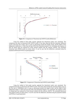
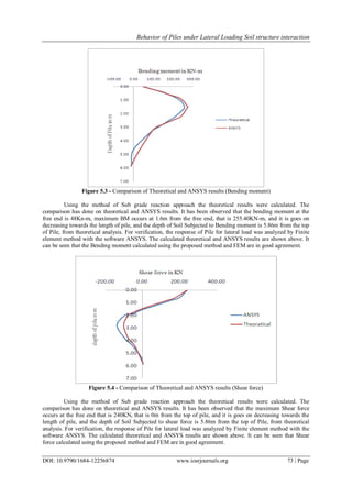
The analysis of laterally loaded piles is done with both theoretical and FEM based ANSYS software. It
has been observed that the analysis of laterally loaded piles can be effectively carried out using ANSYS
software. A Winkler method is adopted for the analysis of laterally loaded piles. The analysis of laterally loaded
pile embedded in a single layer soil profile is carried out. The results show that the calculated deflections, Slope,
Bending moment, Shear force using proposed method agree well with those obtained from FEM with software
ANSYS. This method has the advantage over other procedures in that it is easy to understand and is adaptable to
simple computer programs by engineers.
References
[1]. Shamsher prakash and Hari D. Sharma, “Pile foundations in engineering practice”. John wiley and sons New York - 1990.
[2]. Poulos, H.G. and Davis, E. H, Pile Foundation Analysis and Design. John Wiley & Sons, New York.-1980
[3]. Murugan M, Natarajan C, Muthukkumaran K. “Behavior of laterally loaded piles in cohesionless soils” (2011). International journal
of earth science and engineering
[4]. Rongqing Li and Jinxin Gong. “Analysis of laterally loaded pile in layered soils” (2008). EJGE
[5]. V S Phanikanth, Deepankar choudhury, G Rami reddy. “Response of single pile under lateral loads in cohesionless soils” (2010)
EJGE
[6]. Matlock, H. and Reese, L. C. (1962).” Generalized Solutions for Laterally Loaded Piles. Transactions of the American Society of
Civil Engineers” 12, 1220-1247.
[7]. Hetenyi, M. (1946) “Beams on elastic foundations,” University of Michigan Press, Ann Arbor, Mich., United States.
[8]. Ashour, M., and G. Norris (2000) “Modeling lateral soil–pile response based on soil–pile interaction,” Journal of Geotechnical and
Geoenvironmental Engineering, ASCE, 126(5), pp 420–428.](https://image.slidesharecdn.com/k012256874-160711043425/85/K012256874-7-320.jpg)

This document analyzes the behavior of piles under lateral loading due to soil-structure interaction. It uses the subgrade reaction method to model the soil as a series of elastic springs and analyze the pile as a flexible beam on an elastic foundation. The method is used to calculate the pile deflection, slope, bending moment, and shear force along its length due to a lateral load. These results are validated using finite element modeling in ANSYS software. The document presents an example problem and shows the results from both the subgrade reaction method and ANSYS match well.


![Getting Started with Apache Spark: Big Data Made Simple [Free Meetup]](https://cdn.slidesharecdn.com/ss_thumbnails/apachesparkgettingstarted-260203175547-8361bcc3-thumbnail.jpg?width=640&height=640&fit=bounds)


