This document summarizes the mechanical properties of materials through stress-strain diagrams. It discusses the differences between stress-strain diagrams for ductile versus brittle materials. For ductile materials, the diagram shows elastic behavior, yielding, strain hardening, necking, and true stress-strain. Brittle materials exhibit no yielding and rupture occurs at a much smaller strain. The document also discusses Hooke's law, Poisson's ratio, axial loading of materials, and provides examples of calculating deformation based on applied loads and material properties.
This book is intended to cover the basic Strength of Materials of the first
two years of an engineering degree or diploma course ; it does not attempt
to deal with the more specialized topics which usually comprise the final
year of such courses.
The work has been confined to the mathematical aspect of the subject
and no descriptive matter relating to design or materials testing has been
included.
This is first or introductory lecture of Mechanics of Solids-1 as per curriculum formulated by Higher Education Commission and Pakistan Engineering Council
Bending Stresses are important in the design of beams from strength point of view. The present source gives an idea on theory and problems in bending stresses.
This slide introduces the concept of simple strain, a term used in mechanics to describe the deformation of a material under an applied force. The slide includes a diagram illustrating the deformation of a rectangular object under a tensile force, as well as a formula for calculating strain. Simple strain is a fundamental concept in the study of materials and mechanics, and understanding it is essential for many engineering applications
Mechanics of Materials
Materials Characterization
The American Society for Testing and Materials (ASTM) specifies test procedures for determining the various properties of a material.
These descriptions are guidelines used by experimentalists to obtain reproducible results for material properties.
Strength of Materials Lecture - 2
Elastic stress and strain of materials (stress-strain diagram)
Mehran University of Engineering and Technology.
Department of Mechanical Engineering.
Sachpazis:Terzaghi Bearing Capacity Estimation in simple terms with Calculati...Dr.Costas Sachpazis
Terzaghi's soil bearing capacity theory, developed by Karl Terzaghi, is a fundamental principle in geotechnical engineering used to determine the bearing capacity of shallow foundations. This theory provides a method to calculate the ultimate bearing capacity of soil, which is the maximum load per unit area that the soil can support without undergoing shear failure. The Calculation HTML Code included.
Immunizing Image Classifiers Against Localized Adversary Attacksgerogepatton
This paper addresses the vulnerability of deep learning models, particularly convolutional neural networks
(CNN)s, to adversarial attacks and presents a proactive training technique designed to counter them. We
introduce a novel volumization algorithm, which transforms 2D images into 3D volumetric representations.
When combined with 3D convolution and deep curriculum learning optimization (CLO), itsignificantly improves
the immunity of models against localized universal attacks by up to 40%. We evaluate our proposed approach
using contemporary CNN architectures and the modified Canadian Institute for Advanced Research (CIFAR-10
and CIFAR-100) and ImageNet Large Scale Visual Recognition Challenge (ILSVRC12) datasets, showcasing
accuracy improvements over previous techniques. The results indicate that the combination of the volumetric
input and curriculum learning holds significant promise for mitigating adversarial attacks without necessitating
adversary training.
NO1 Uk best vashikaran specialist in delhi vashikaran baba near me online vas...Amil Baba Dawood bangali
Contact with Dawood Bhai Just call on +92322-6382012 and we'll help you. We'll solve all your problems within 12 to 24 hours and with 101% guarantee and with astrology systematic. If you want to take any personal or professional advice then also you can call us on +92322-6382012 , ONLINE LOVE PROBLEM & Other all types of Daily Life Problem's.Then CALL or WHATSAPP us on +92322-6382012 and Get all these problems solutions here by Amil Baba DAWOOD BANGALI
#vashikaranspecialist #astrologer #palmistry #amliyaat #taweez #manpasandshadi #horoscope #spiritual #lovelife #lovespell #marriagespell#aamilbabainpakistan #amilbabainkarachi #powerfullblackmagicspell #kalajadumantarspecialist #realamilbaba #AmilbabainPakistan #astrologerincanada #astrologerindubai #lovespellsmaster #kalajaduspecialist #lovespellsthatwork #aamilbabainlahore#blackmagicformarriage #aamilbaba #kalajadu #kalailam #taweez #wazifaexpert #jadumantar #vashikaranspecialist #astrologer #palmistry #amliyaat #taweez #manpasandshadi #horoscope #spiritual #lovelife #lovespell #marriagespell#aamilbabainpakistan #amilbabainkarachi #powerfullblackmagicspell #kalajadumantarspecialist #realamilbaba #AmilbabainPakistan #astrologerincanada #astrologerindubai #lovespellsmaster #kalajaduspecialist #lovespellsthatwork #aamilbabainlahore #blackmagicforlove #blackmagicformarriage #aamilbaba #kalajadu #kalailam #taweez #wazifaexpert #jadumantar #vashikaranspecialist #astrologer #palmistry #amliyaat #taweez #manpasandshadi #horoscope #spiritual #lovelife #lovespell #marriagespell#aamilbabainpakistan #amilbabainkarachi #powerfullblackmagicspell #kalajadumantarspecialist #realamilbaba #AmilbabainPakistan #astrologerincanada #astrologerindubai #lovespellsmaster #kalajaduspecialist #lovespellsthatwork #aamilbabainlahore #Amilbabainuk #amilbabainspain #amilbabaindubai #Amilbabainnorway #amilbabainkrachi #amilbabainlahore #amilbabaingujranwalan #amilbabainislamabad
Cosmetic shop management system project report.pdfKamal Acharya
Buying new cosmetic products is difficult. It can even be scary for those who have sensitive skin and are prone to skin trouble. The information needed to alleviate this problem is on the back of each product, but it's thought to interpret those ingredient lists unless you have a background in chemistry.
Instead of buying and hoping for the best, we can use data science to help us predict which products may be good fits for us. It includes various function programs to do the above mentioned tasks.
Data file handling has been effectively used in the program.
The automated cosmetic shop management system should deal with the automation of general workflow and administration process of the shop. The main processes of the system focus on customer's request where the system is able to search the most appropriate products and deliver it to the customers. It should help the employees to quickly identify the list of cosmetic product that have reached the minimum quantity and also keep a track of expired date for each cosmetic product. It should help the employees to find the rack number in which the product is placed.It is also Faster and more efficient way.
Final project report on grocery store management system..pdfKamal Acharya
In today’s fast-changing business environment, it’s extremely important to be able to respond to client needs in the most effective and timely manner. If your customers wish to see your business online and have instant access to your products or services.
Online Grocery Store is an e-commerce website, which retails various grocery products. This project allows viewing various products available enables registered users to purchase desired products instantly using Paytm, UPI payment processor (Instant Pay) and also can place order by using Cash on Delivery (Pay Later) option. This project provides an easy access to Administrators and Managers to view orders placed using Pay Later and Instant Pay options.
In order to develop an e-commerce website, a number of Technologies must be studied and understood. These include multi-tiered architecture, server and client-side scripting techniques, implementation technologies, programming language (such as PHP, HTML, CSS, JavaScript) and MySQL relational databases. This is a project with the objective to develop a basic website where a consumer is provided with a shopping cart website and also to know about the technologies used to develop such a website.
This document will discuss each of the underlying technologies to create and implement an e- commerce website.
Hybrid optimization of pumped hydro system and solar- Engr. Abdul-Azeez.pdffxintegritypublishin
Advancements in technology unveil a myriad of electrical and electronic breakthroughs geared towards efficiently harnessing limited resources to meet human energy demands. The optimization of hybrid solar PV panels and pumped hydro energy supply systems plays a pivotal role in utilizing natural resources effectively. This initiative not only benefits humanity but also fosters environmental sustainability. The study investigated the design optimization of these hybrid systems, focusing on understanding solar radiation patterns, identifying geographical influences on solar radiation, formulating a mathematical model for system optimization, and determining the optimal configuration of PV panels and pumped hydro storage. Through a comparative analysis approach and eight weeks of data collection, the study addressed key research questions related to solar radiation patterns and optimal system design. The findings highlighted regions with heightened solar radiation levels, showcasing substantial potential for power generation and emphasizing the system's efficiency. Optimizing system design significantly boosted power generation, promoted renewable energy utilization, and enhanced energy storage capacity. The study underscored the benefits of optimizing hybrid solar PV panels and pumped hydro energy supply systems for sustainable energy usage. Optimizing the design of solar PV panels and pumped hydro energy supply systems as examined across diverse climatic conditions in a developing country, not only enhances power generation but also improves the integration of renewable energy sources and boosts energy storage capacities, particularly beneficial for less economically prosperous regions. Additionally, the study provides valuable insights for advancing energy research in economically viable areas. Recommendations included conducting site-specific assessments, utilizing advanced modeling tools, implementing regular maintenance protocols, and enhancing communication among system components.
Pile Foundation by Venkatesh Taduvai (Sub Geotechnical Engineering II)-conver...
Mm210(4)
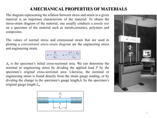
1. 4.MECHANICAL PROPERTIES OF MATERIALS
The diagram representing the relation between stress and strain in a given material is an important characteristic of the material. To obtain the stress-strain diagram of the material, one usually conducts a tensile test on a specimen of the material such as metals,ceramics, polymers and composites.
The values of normal stress and extensional strain that are used in plotting a conventional stress-strain diagram are the engineering stress and engineering strain.
A0 is the specimen’s initial cross-sectional area. We can determine the nominal or engineering stress by dividing the applied load P by the specimen’s original cross-sectional area. Likewise, the nominal or engineering strain is found directly from the strain gauge reading, or by dividing the change in the specimen’s gauge length,δ, by the specimen’s original gauge length L0.
1
2. It is possible to distinguish some common characteristics among the stress-strain diagrams of various groups of materials and to divide materials into two broad categories on the basis of these characteristics, namely, ductile materials and the brittle materials.
2
Stress-strain diagram for ductile materials.
Elastic Behavior. Here the curve is actually a straight line throughout most of this region, so that the stress is proportional to the strain. The material in this region is said to be linear elastic. The upper stress limit to this linear relationship is called proportional limit, PL .If the stress exceeds this limit, the curve tends to bend and flatten out as shown. This continues until the stress reaches the elastic limit. Upon reaching this point, if the load is removed the specimen will still return back to its original shape.
Yielding. A slight increase in stress above the elastic limit will result in a breakdown of the material and cause it to deform permanently. This behavior is called yielding. The stress that causes yielding is called the yield stress or yield point, Y , and the deformation that occurs is called plastic deformation. Although not shown in the diagram,for low-carbon steels or those that are hot rolled, the yield point is often distinguished by two values. The upper yield point occurs first, followed by a sudden decrease in load-carrying capacity to a lower yield point. Notice that once the yield point is reached, then the specimen will continue to elongate without any increase in load. When the material is in this state, it is often referred to as being perfectly plastic.
3. 3
Strain Hardening. When yielding has ended, an increase in load can be supported by the specimen, resulting in a curve that rises continuously but becames flatter until it reaches a maximum stress referred to as the ultimate stress, u .the rise in the curve in this manner is called strain hardening.
Necking. Up to the ultimate stress, as the specimen elongates, its cross-sectional area will decrease. This decrease is fairly uniform over the specimen’s entire gauge length; however, just after, at the ultimate stress, the cross-sectional area will begin to decrease in a localized region of the specimen. As a result, a constriction or neck tends to form in this region as the specimen elongates further. Here the stress-strain diagram tends to curve downward until the specimen breaks at the fracture stress, f
True stress-strain diagram. Instead of always using the original length and cross-sectional area to calculate the stress and strain, we could have used the actual area and length at the instant the load is measured. Note that the conventional and true diagrams are practically coincedent when the strain is small. Although the diagrams are different, most engineering design is done so that the material support a stress within the elastic range.
4. Off-set method for some ductile materials
For materials like aluminum that have no clearly defined yield point, a stress value called the offset yield stress, is used as a yield-point stress.
As illustrated in figure, the offset yield stress is determined by first drawing a straight line that fits the data in initial portion of stress-strain diagram. A second line is then drawn parallel to the original line but offset by a specified amount of strain. The intersection of this second line with the stress-strain curve determine the offset yield stress. In figure the commenly used offset value of 0.002 is illustrated.
4
5. Stress-strain diagram for brittle materials.
Brittle materials, which comprise cast iron, glass and stone are characterized by the fact that rupture occurs without any noticable prior change in the rate of elongation. Thus, for brittle materials, there is no difference between the ultimate strength and the breaking strength.
Also, the strain at the time of rupture is much smaller for brittle than for ductile materials. From the figures, we note the absence of any necking of the specimen in the case of brittle material, and observe that rupture occurs along a surface perpendicular to the load.
5
6. 6
Hooke’s Law and Poisson’s Ratio .
Most engineering structures are designed to undergo relatively small deformations, involving only the straight-line portion of the corresponding stress-strain diagram. For that initial portion of the diagramm the stress is directly proportional to the strain and we can write,
This relation is known as Hooke’s law.
Associated with the elongation of a member in
axial tension, there is a transverse contraction.The
transverse contraction during a tensile test is
related to the longitudinal elongation by
Where ν (greek symbol nu) is Poisson’s ratio. Poisson’s ratio is dimensionless, with typical values in the 0.25-0.35 range. For orientation of axes in figure the transverse strains are related to the longitudinal strain by
∈푦=∈푧=−휈∈푥
7. 7
Example 4.1
The acrylic plastic rod is 200 mm long and 15 mm in diameter. If an axial load of 300 N is applied to it, determine the change in its length and the change in its diameter. Ep = 2.70 GPa, νp = 0.4.
8. 8
5. AXIAL LOAD
• A structural member having a straight longitudinal axis is said to undergo axial deformation if, when
loads are applied to the member or it is subjected to temperature change: (1) the axis of the member
remains straight, and (2) cross sections of the member remain plane, remain perpendicular to the axis,
and do not rotate about the axis as the member deforms.
ELASTIC DEFORMATION OF AN AXIALLY LOADED
MEMBER
Using the method of sections, a differential element of length
dx and cross-sectional area A(x) is isolated from the bar at the
arbitrary position x. The resultant internal axial force P(x) will
deform the element into the shape indicated by dashed outline.
The stress and strain in the element are
Using the Hooke’s law
( )
( )
P x
A x
d
dx
( ) ( )
( ) ( )
P x d P x dx
E E d
A x dx A x E
9. 9
For the entire length L of the bar, we must integrate this expression to find the required end displacement. This yields
훿= 푃푥푑푥 퐴푥퐸 퐿 0
Where
δ : displacement of one point on the bar relative to another point
L : distance between the points
P(x) : internal axial force at the section, located a distance x from one end
A(x) : cross sectional area of the bar, expressed as a function of x
E : modulus of elasticity for the material
Constant Load and Cross-Sectional Area. In many cases the bar will have a constant cross- sectional area A; and the material will be homogeneous, so E is constant. Furthermore, if a constant external force is applied at each end, then the internal force P throughout the length of the bar is also constant.
PLAE
10. If the bar is subjected to several different axial forces, or the cross-sectional area or modulus of elasticity changes abruptly from one region of the bar to the next, the above equation can be applied to each segment of the bar where these quantities are all constant. The displacement of one end of the bar with respect to the other is then found from the vectr addition of the end displacements of each segment.
Sign Convention. In order to apply this equation we must develop a sign convention for the internal force and the displacement of one end of the bar with respect to the other end. We will consider both the force and displacement to be positive if they cause tension and elongation, respectively, whereas a negative force and displacement will cause compression and contraction, respectively.
10
11. Determine the deformation of the steel rod shown in figure under
the given loads.
11
Example 5.1(Beer&Johnston)
6 E 29(10 ) psi
12. 12
Example 5.2
Rigid beam AB rests on the two short posts shown in the figure. AC is made of steel and has a diameter of 20 mm, and BD is made of aluminum and has a diameter of 40 mm. Determine the displacement of point F on AB if a vertical load of 90 kN is applied over this point. Take
Est = 200 GPa, Eal = 70 GPa
13. 13
Example 5.3 (Beer&Johnston)
The rigid bar BDE is supported by two links AB and CD. Link AB is made of aluminum (E = 70 GPa) and has a cross-sectional area of 500 mm2; link CD is made of steel ( E = 200 GPa) and has a cross-sectional area of 600 mm2. for the 30-kN force shown, determine the deflection (a) of B, (b) of D, (c) of E.
14. 14
Example 5.4
The assembly consists of three titanium (Ti-6A1-4V) rods and a rigid bar AC. The cross-sectional area of each rod is given in the figure. If a force of 6 kip is applied to the ring F, determine the angle of tilt of bar AC.
E = 17.4 (103) ksi