Downloaded 103 times
![Note
“Asked Objective Questions” is the total collection of questions from:-
20 yrs IES (2010-1992) [Engineering Service Examination]
21 yrs. GATE (2011-1992)
and 14 yrs. IAS (Prelim.) [Civil Service Preliminary]
Copyright © 2007 S K Mondal
Every effort has been made to see that there are no errors (typographical or otherwise) in the
material presented. However, it is still possible that there are a few errors (serious or
otherwise). I would be thankful to the readers if they are brought to my attention at the
following e-mail address: swapan_mondal_01@yahoo.co.in
S K Mondal
Page 2 of 429](https://image.slidesharecdn.com/strengthofmaterialsbyskmondal-130102103545-phpapp02-150924095946-lva1-app6891/85/Strengthofmaterialsbyskmondal-130102103545-phpapp02-2-320.jpg)
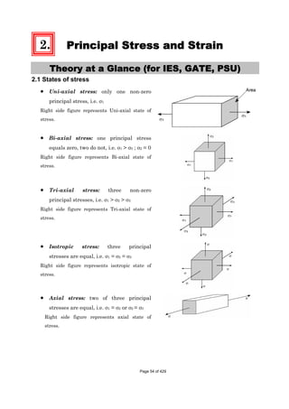
![Chapter-1 Stress and Strain S K Mondal’s
99 100 1
0.01 (Dimensionless)compressive
100 100
o
c
o o
L LL mm mm mm
L L mm mm
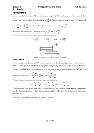
Shear Strain ( ): When a
force P is applied tangentially to
the element shown. Its edge
displaced to dotted line. Where
is the lateral displacement of
the upper face
of the element relative to the lower face and L is the distance between these faces.
Then the shear strain is ( )
L
Let us take an example: A block 100 mm × 100 mm base and 10 mm height. When we apply a
tangential force 10 kN to the upper edge it is displaced 1 mm relative to lower face.
Then the direct shear stress in the element
( )
3
210 10 10
1N/mm 1MPa
100 100 100 100
kN N
mm mm mm mm
And shear strain in the element ( ) =
1
0.1
10
mm
mm
Dimensionless
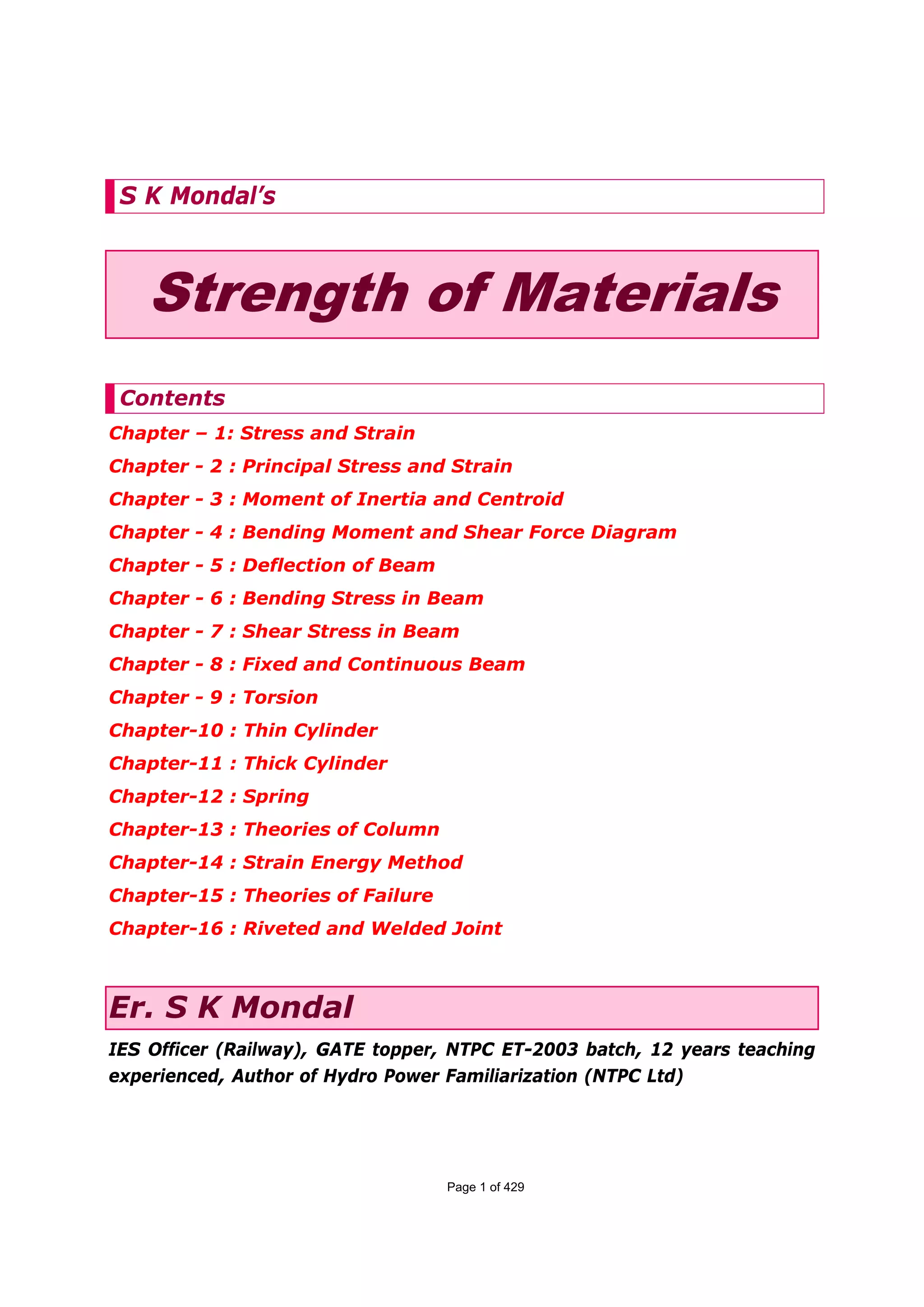
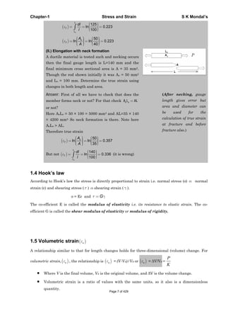
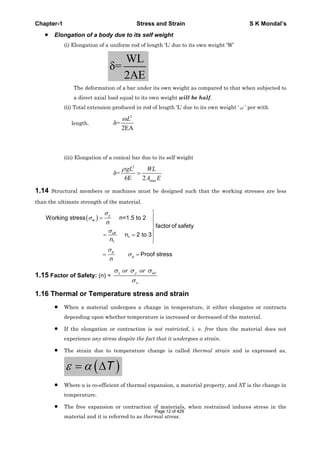
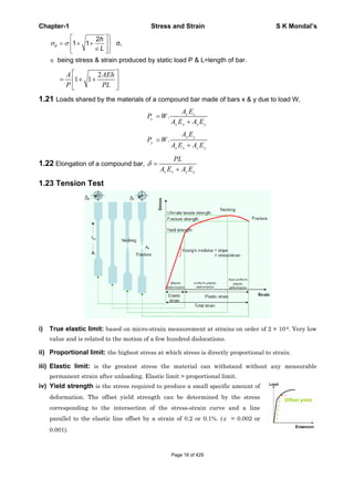
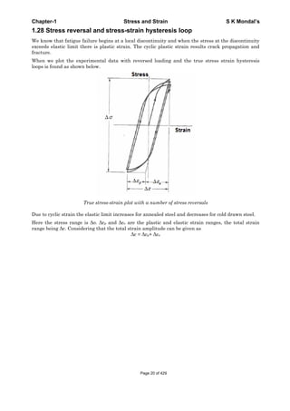
1.3 True stress and True Strain
The true stress is defined as the ratio of the load to the cross section area at any instant.
load
Instantaneous area
T
1
Where and is the engineering stress and engineering strain respectively.
True strain
ln ln 1 ln 2ln
o
L
o o
T
oL
A ddl L
l L A d
or engineering strain ( ) = T
e -1
The volume of the specimen is assumed to be constant during plastic deformation.
[ o oA L AL ] It is valid till the neck formation.
Comparison of engineering and the true stress-strain curves shown below
Page 5 of 429](https://image.slidesharecdn.com/strengthofmaterialsbyskmondal-130102103545-phpapp02-150924095946-lva1-app6891/85/Strengthofmaterialsbyskmondal-130102103545-phpapp02-5-320.jpg)
![Chapter-1 Stress and Strain S K Mondal’s
V/V= volumetric strain = x + y + z = 1 + 2 + 3
Dilation: The hydrostatic component of the total stress contributes to deformation by
changing the area (or volume, in three dimensions) of an object. Area or volume change is
called dilation and is positive or negative, as the volume increases or decreases,
respectively.
p
e
K
Where p is pressure.
1.6 Young’s modulus or Modulus of elasticity (E) =
PL
=
A
1.7 Modulus of rigidity or Shear modulus of elasticity (G) = =
PL
A
1.8 Bulk Modulus or Volume modulus of elasticity (K) =
p p
v R
v R
1.10 Relationship between the elastic constants E, G, K, μ
9KG
E 2G 1 3K 1 2
3K G [VIMP]
Where K = Bulk Modulus, = Poisson’s Ratio, E= Young’s modulus, G= Modulus of rigidity
For a linearly elastic, isotropic and homogeneous material, the number of elastic
constants required to relate stress and strain is two. i.e. any two of the four must be
known.
If the material is non-isotropic (i.e. anisotropic), then the elastic modulii will vary with
additional stresses appearing since there is a coupling between shear stresses and
normal stresses for an anisotropic material.
Let us take an example: The modulus of elasticity and rigidity of a material are 200 GPa and 80
GPa, respectively. Find all other elastic modulus.
Answer: Using the relation
9KG
E 2G 1 3K 1 2
3K G
we may find all other elastic modulus
easily
Poisson’s Ratio
E E 200
( ) : 1 1 1 0.25
2G 2G 2 80
Bulk Modulus (K) :
E E 200
3K K 133.33GPa
1 2 3 1 2 3 1 2 0.25
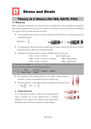
1.11 Poisson’s Ratio (μ)
=
Transverse strainor lateral strain
Longitudinal strain
=
y
x
(Under unidirectional stress in x-direction)
The theory of isotropic elasticity allows Poisson's ratios in the range from -1 to 1/2.
Poisson's ratio in various materials Page 8 of 429](https://image.slidesharecdn.com/strengthofmaterialsbyskmondal-130102103545-phpapp02-150924095946-lva1-app6891/85/Strengthofmaterialsbyskmondal-130102103545-phpapp02-8-320.jpg)
![Chapter-1 Stress and Strain S K Mondal’s
OBJECTIVE QUESTIONS (GATE, IES, IAS)
Previous 20-Years GATE Questions
Stress in a bar due to self-weight
GATE-1. Two identical circular rods of same diameter and same length are subjected to
same magnitude of axial tensile force. One of the rods is made out of mild steel
having the modulus of elasticity of 206 GPa. The other rod is made out of cast
iron having the modulus of elasticity of 100 GPa. Assume both the materials to
be homogeneous and isotropic and the axial force causes the same amount of
uniform stress in both the rods. The stresses developed are within the
proportional limit of the respective materials. Which of the following
observations is correct? [GATE-2003]
(a) Both rods elongate by the same amount
(b) Mild steel rod elongates more than the cast iron rod
(c) Cast iron rod elongates more than the mild steel rod
(d) As the stresses are equal strains are also equal in both the rods
GATE-1. Ans. (c)
PL 1
L or L [AsP, L and A is same]
AE E
mild steel CI
CI MS
MSC.I
L E 100
L L
L E 206
GATE-2. A steel bar of 40 mm × 40 mm square cross-section is subjected to an axial
compressive load of 200 kN. If the length of the bar is 2 m and E = 200 GPa, the
elongation of the bar will be: [GATE-2006]
(a) 1.25 mm (b) 2.70 mm (c) 4.05 mm (d) 5.40 mm
GATE-2. Ans. (a) 9
200 1000 2PL
L m 1.25mm
AE 0.04 0.04 200 10
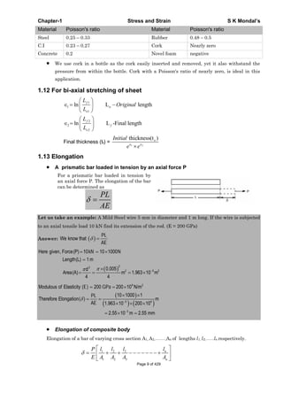
True stress and true strain
GATE-3. The ultimate tensile strength of a material is 400 MPa and the elongation up to
maximum load is 35%. If the material obeys power law of hardening, then the
true stress-true strain relation (stress in MPa) in the plastic deformation range
is: [GATE-2006]
(a) 0.30
540 (b) 0.30
775 (c) 0.35
540 (d) 0.35
775
GATE-3. Ans. (c)
A true stress – true strain curve in
tension n
k
k = Strength co-efficient = 400 ×
(1.35) = 540 MPa
n = Strain – hardening exponent =
0.35
Elasticity and Plasticity
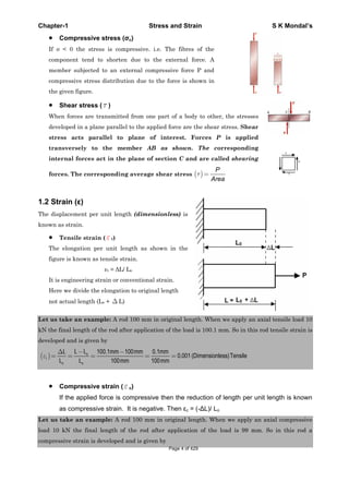
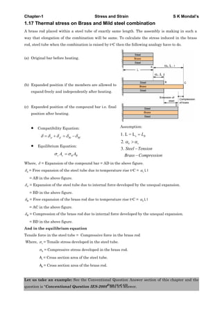
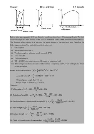
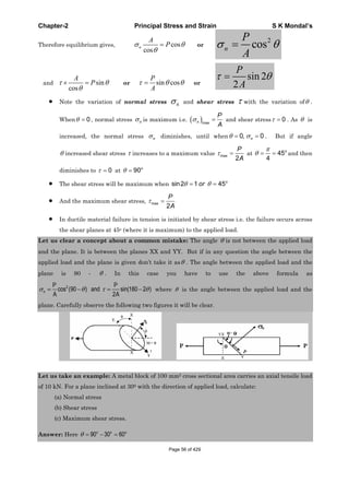
GATE-4. An axial residual compressive stress due to a manufacturing process is present
on the outer surface of a rotating shaft subjected to bending. Under a given
Page 21 of 429](https://image.slidesharecdn.com/strengthofmaterialsbyskmondal-130102103545-phpapp02-150924095946-lva1-app6891/85/Strengthofmaterialsbyskmondal-130102103545-phpapp02-21-320.jpg)
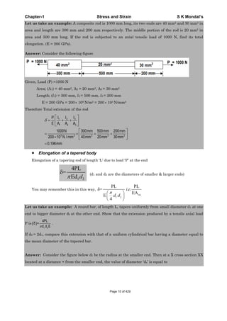
![Chapter-1 Stress and Strain S K Mondal’s
bending load, the fatigue life of the shaft in the presence of the residual
compressive stress is: [GATE-2008]
(a) Decreased
(b) Increased or decreased, depending on the external bending load
(c) Neither decreased nor increased
(d) Increased
GATE-4. Ans. (d)
A cantilever-loaded rotating beam, showing the normal distribution of surface stresses.
(i.e., tension at the top and compression at the bottom)
The residual compressive stresses induced.
Net stress pattern obtained when loading a surface treated beam. The reduced
magnitude of the tensile stresses contributes to increased fatigue life.
GATE-5. A static load is mounted at the centre of a shaft rotating at uniform angular
velocity. This shaft will be designed for [GATE-2002]
(a) The maximum compressive stress (static) (b) The maximum tensile stress (static)
(c) The maximum bending moment (static) (d) Fatigue loading
GATE-5. Ans. (d)
GATE-6. Fatigue strength of a rod subjected to cyclic axial force is less than that of a
rotating beam of the same dimensions subjected to steady lateral force because
(a) Axial stiffness is less than bending stiffness [GATE-1992]
(b) Of absence of centrifugal effects in the rod
(c) The number of discontinuities vulnerable to fatigue are more in the rod
(d) At a particular time the rod has only one type of stress whereas the beam has both
the tensile and compressive stresses.
GATE-6. Ans. (d)
Relation between the Elastic Modulii
GATE-7. A rod of length L and diameter D is subjected to a tensile load P. Which of the
following is sufficient to calculate the resulting change in diameter?
(a) Young's modulus (b) Shear modulus [GATE-2008]
(c) Poisson's ratio (d) Both Young's modulus and shear modulus
Page 22 of 429](https://image.slidesharecdn.com/strengthofmaterialsbyskmondal-130102103545-phpapp02-150924095946-lva1-app6891/85/Strengthofmaterialsbyskmondal-130102103545-phpapp02-22-320.jpg)
![Chapter-1 Stress and Strain S K Mondal’s
GATE-7. Ans. (d) For longitudinal strain we need Young's modulus and for calculating transverse
strain we need Poisson's ratio. We may calculate Poisson's ratio from )1(2GE for
that we need Shear modulus.
GATE-8. In terms of Poisson's ratio (μ) the ratio of Young's Modulus (E) to Shear
Modulus (G) of elastic materials is
[GATE-2004]
1 1
( )2(1 ) ( )2(1 ) ( ) (1 ) ( ) (1 )
2 2
a b c d
GATE-8. Ans. (a)
GATE-9. The relationship between Young's modulus (E), Bulk modulus (K) and Poisson's
ratio (μ) is given by: [GATE-2002]
(a) E 3 K 1 2 (b) K 3 E 1 2
(c) E 3 K 1 (d) K 3 E 1
GATE-9. Ans. (a)
9KG
Remember E 2G 1 3K 1 2
3K G
Stresses in compound strut
GATE-10. In a bolted joint two members
are connected with an axial
tightening force of 2200 N. If
the bolt used has metric
threads of 4 mm pitch, then
torque required for achieving
the tightening force is
(a) 0.7Nm (b) 1.0 Nm
(c) 1.4Nm (d) 2.8Nm [GATE-2004]
GATE-10. Ans. (c)
0.004
T F r 2200 Nm 1.4Nm
2
GATE-11. The figure below shows a steel rod of 25 mm2 cross sectional area. It is loaded
at four points, K, L, M and N. [GATE-2004, IES 1995, 1997, 1998]
Assume Esteel = 200 GPa. The total change in length of the rod due to loading is:
(a) 1 μm (b) -10 μm (c) 16 μm (d) -20 μm
GATE-11. Ans. (b) First draw FBD of all parts separately then
Total change in length =
PL
AE
GATE-12. A bar having a cross-sectional area of 700mm2 is subjected to axial loads at the
positions indicated. The value of stress in the segment QR is: [GATE-2006]
Page 23 of 429](https://image.slidesharecdn.com/strengthofmaterialsbyskmondal-130102103545-phpapp02-150924095946-lva1-app6891/85/Strengthofmaterialsbyskmondal-130102103545-phpapp02-23-320.jpg)
![Chapter-1 Stress and Strain S K Mondal’s
P Q R S
(a) 40 MPa (b) 50 MPa (c) 70 MPa (d) 120 MPa
GATE-12. Ans. (a)
F.B.D
QR
P 28000
MPa 40MPa
A 700
GATE-13. An ejector mechanism consists of a
helical compression spring having a
spring constant of K = 981 × 103 N/m.
It is pre-compressed by 100 mm
from its free state. If it is used to
eject a mass of 100 kg held on it, the
mass will move up through a
distance of
(a) 100mm (b) 500mm
(c) 981 mm (d) 1000mm
[GATE-2004]
GATE-13. Ans. (a) No calculation needed it is pre-
compressed by 100 mm from its free
state. So it can’t move more than 100
mm. choice (b), (c) and (d) out.
GATE-14. The figure shows a pair of pin-jointed
gripper-tongs holding an object
weighing 2000 N. The co-efficient of
friction (μ) at the gripping surface is
0.1 XX is the line of action of the
input force and YY is the line of
application of gripping force. If the
pin-joint is assumed to be
frictionless, then magnitude of force
F required to hold the weight is:
(a) 1000 N
(b) 2000 N
(c) 2500 N
(d) 5000 N
[GATE-2004]
GATE-14. Ans. (d) Frictional force required = 2000 N
Force needed to produce 2000N frictional force at Y-Y section =
2000
20000N
0.1
So for each side we need (Fy) = 10000 N force Page 24 of 429](https://image.slidesharecdn.com/strengthofmaterialsbyskmondal-130102103545-phpapp02-150924095946-lva1-app6891/85/Strengthofmaterialsbyskmondal-130102103545-phpapp02-24-320.jpg)
![Chapter-1 Stress and Strain S K Mondal’s
Taking moment about PIN
y
y
F 50 10000 50
F 50 F 100 or F 5000N
100 100
GATE-15. A uniform, slender cylindrical rod is made of a homogeneous and isotropic
material. The rod rests on a frictionless surface. The rod is heated uniformly. If
the radial and longitudinal thermal stresses are represented by r and z,
respectively, then [GATE-2005]
( ) 0, 0 ( ) 0, 0 ( ) 0, 0 ( ) 0, 0r z r z r z r za b c d
GATE-15. Ans. (a) Thermal stress will develop only when you prevent the material to
contrast/elongate. As here it is free no thermal stress will develop.
Tensile Test
GATE-16. A test specimen is stressed slightly beyond the yield point and then unloaded.
Its yield strength will [GATE-1995]
(a) Decrease (b) Increase
(c) Remains same (d) Becomes equal to ultimate tensile strength
GATE-16. Ans. (b)
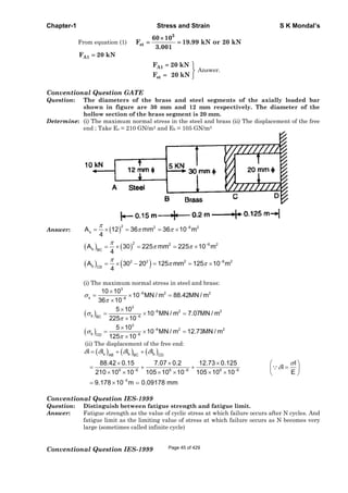
GATE-17. Under repeated loading a
material has the stress-strain
curve shown in figure, which of
the following statements is
true?
(a) The smaller the shaded area,
the better the material damping
(b) The larger the shaded area, the
better the material damping
(c) Material damping is an
independent material property
and does not depend on this
curve
(d) None of these
[GATE-1999]
GATE-17. Ans. (a)
Previous 20-Years IES Questions
Stress in a bar due to self-weight
IES-1. A solid uniform metal bar of diameter D and length L is hanging vertically
from its upper end. The elongation of the bar due to self weight is: [IES-2005]
(a) Proportional to L and inversely proportional to D2
(b) Proportional to L2 and inversely proportional to D2
(c) Proportional of L but independent of D
(d) Proportional of U but independent of DPage 25 of 429](https://image.slidesharecdn.com/strengthofmaterialsbyskmondal-130102103545-phpapp02-150924095946-lva1-app6891/85/Strengthofmaterialsbyskmondal-130102103545-phpapp02-25-320.jpg)
![Chapter-1 Stress and Strain S K Mondal’s
IES-1. Ans. (a) 2 2
WL WL 1
L &
2AE D D
2 E
4
IES-2. The deformation of a bar under its own weight as compared to that when
subjected to a direct axial load equal to its own weight will be: [IES-1998]
(a) The same (b) One-fourth (c) Half (d) Double
IES-2. Ans. (c)
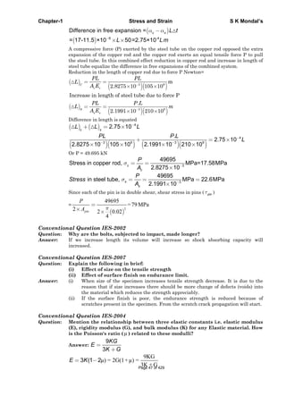
IES-3. A rigid beam of negligible weight is supported in a horizontal position by two
rods of steel and aluminum, 2 m and 1 m long having values of cross - sectional
areas 1 cm2 and 2 cm2 and E of 200 GPa and 100 GPa respectively. A load P is
applied as shown in the figure [IES-2002]
If the rigid beam is to remain horizontal then
(a) The forces on both sides should be equal
(b) The force on aluminum rod should be twice the force on steel
(c) The force on the steel rod should be twice the force on aluminum
(d) The force P must be applied at the centre of the beam
IES-3. Ans. (b)
Bar of uniform strength
IES-4. Which one of the following statements is correct? [IES 2007]
A beam is said to be of uniform strength, if
(a) The bending moment is the same throughout the beam
(b) The shear stress is the same throughout the beam
(c) The deflection is the same throughout the beam
(d) The bending stress is the same at every section along its longitudinal axis
IES-4. Ans. (d)
IES-5. Which one of the following statements is correct? [IES-2006]
Beams of uniform strength vary in section such that
(a) bending moment remains constant (b) deflection remains constant
(c) maximum bending stress remains constant (d) shear force remains constant
IES-5. Ans. (c)
IES-6. For bolts of uniform strength, the shank diameter is made equal to [IES-2003]
(a) Major diameter of threads (b) Pitch diameter of threads
(c) Minor diameter of threads (d) Nominal diameter of threads
IES-6. Ans. (c)
IES-7. A bolt of uniform strength can be developed by [IES-1995]
(a) Keeping the core diameter of threads equal to the diameter of unthreaded portion
of the bolt
(b) Keeping the core diameter smaller than the diameter of the unthreaded portion
Page 26 of 429](https://image.slidesharecdn.com/strengthofmaterialsbyskmondal-130102103545-phpapp02-150924095946-lva1-app6891/85/Strengthofmaterialsbyskmondal-130102103545-phpapp02-26-320.jpg)
![Chapter-1 Stress and Strain S K Mondal’s
(c) Keeping the nominal diameter of threads equal the diameter of unthreaded portion
of the bolt
(d) One end fixed and the other end free
IES-7. Ans. (a)
Elongation of a Taper Rod
IES-8. Two tapering bars of the same material are subjected to a tensile load P. The
lengths of both the bars are the same. The larger diameter of each of the bars is
D. The diameter of the bar A at its smaller end is D/2 and that of the bar B is
D/3. What is the ratio of elongation of the bar A to that of the bar B? [IES-2006]
(a) 3 : 2 (b) 2: 3 (c) 4 : 9 (d) 1: 3
IES-8. Ans. (b) Elongation of a taper rod
1 2
PL
l
d d E
4
2A B
2B A
l d D / 3 2
or
l d D / 2 3
IES-9. A bar of length L tapers uniformly from diameter 1.1 D at one end to 0.9 D at
the other end. The elongation due to axial pull is computed using mean
diameter D. What is the approximate error in computed elongation? [IES-2004]
(a) 10% (b) 5% (c) 1% (d) 0.5%
IES-9. Ans. (c) act
1 2
PL PL
Actual elongation of the bar l
d d E 1.1D 0.9D E
4 4
2Cal
2
act cal
cal
PL
Calculated elongation of the bar l
D
E
4
l l D
Error % 100 1 100% 1%
l 1.1D 0.9D
IES-10. The stretch in a steel rod of circular section, having a length 'l' subjected to a
tensile load' P' and tapering uniformly from a diameter d1 at one end to a
diameter d2 at the other end, is given [IES-1995]
(a)
1 24
Pl
Ed d
(b)
1 2
.pl
Ed d
(c)
1 2
.
4
pl
Ed d
(d)
1 2
4pl
Ed d
IES-10. Ans. (d) act
1 2
PL
Actual elongation of the bar l
d d E
4
IES-11. A tapering bar (diameters of end sections being d1 and d2 a bar of uniform
cross-section ’d’ have the same length and are subjected the same axial pull.
Both the bars will have the same extension if’d’ is equal to [IES-1998]
1 2 1 2 1 2
1 2a b c d
2 2 2
d d d d d d
d d
IES-11. Ans. (b)
Poisson’s ratio
IES-12. In the case of an engineering material under unidirectional stress in the x-
direction, the Poisson's ratio is equal to (symbols have the usual meanings)
[IAS 1994, IES-2000]
Page 27 of 429](https://image.slidesharecdn.com/strengthofmaterialsbyskmondal-130102103545-phpapp02-150924095946-lva1-app6891/85/Strengthofmaterialsbyskmondal-130102103545-phpapp02-27-320.jpg)
![Chapter-1 Stress and Strain S K Mondal’s
(a)
x
y
(b)
x
y
(c)
x
y
(d)
x
y
IES-12. Ans. (a)
IES-13. Which one of the following is correct in respect of Poisson's ratio (v) limits for
an isotropic elastic solid? [IES-2004]
(a) (b) 1/ 4 1/ 3 (c) 1 1/ 2 (d) 1/ 2 1/ 2
IES-13. Ans. (c) Theoretically 1 1/ 2 but practically 0 1/ 2
IES-14. Match List-I (Elastic properties of an isotropic elastic material) with List-II
(Nature of strain produced) and select the correct answer using the codes
given below the Lists: [IES-1997]
List-I List-II
A. Young's modulus 1. Shear strain
B. Modulus of rigidity 2. Normal strain
C. Bulk modulus 3. Transverse strain
D. Poisson's ratio 4. Volumetric strain
Codes: A B C D A B C D
(a) 1 2 3 4 (b) 2 1 3 4
(c) 2 1 4 3 (d) 1 2 4 3
IES-14. Ans. (c)
IES-15. If the value of Poisson's ratio is zero, then it means that [IES-1994]
(a) The material is rigid.
(b) The material is perfectly plastic.
(c) There is no longitudinal strain in the material
(d) The longitudinal strain in the material is infinite.
IES-15. Ans. (a) If Poisson's ratio is zero, then material is rigid.
IES-16. Which of the following is true (μ= Poisson's ratio) [IES-1992]
(a) 0 1/ 2 (b) 1 0 (c) 1 1 (d)
IES-16. Ans. (a)
Elasticity and Plasticity
IES-17. If the area of cross-section of a wire is circular and if the radius of this circle
decreases to half its original value due to the stretch of the wire by a load, then
the modulus of elasticity of the wire be: [IES-1993]
(a) One-fourth of its original value (b) Halved (c) Doubled (d) Unaffected
IES-17. Ans. (d) Note: Modulus of elasticity is the property of material. It will remain same.
IES-18. The relationship between the Lame’s constant ‘ ’, Young’s modulus ‘E’ and the
Poisson’s ratio ‘ ’ [IES-1997]
a ( ) c d
1 1 2 1 2 1 1 1
E E E E
b
IES-18. Ans. (a)
IES-19. Which of the following pairs are correctly matched? [IES-1994]
1. Resilience…………… Resistance to deformation.
2. Malleability …………..Shape change.
3. Creep ........................ Progressive deformation.
4. Plasticity .... ………….Permanent deformation.
Select the correct answer using the codes given below:
Codes: (a) 2, 3 and 4 (b) 1, 2 and 3 (c) 1, 2 and 4 (d) 1, 3 and 4
IES-19. Ans. (a) Strain energy stored by a body within elastic limit is known as resilience.
Page 28 of 429](https://image.slidesharecdn.com/strengthofmaterialsbyskmondal-130102103545-phpapp02-150924095946-lva1-app6891/85/Strengthofmaterialsbyskmondal-130102103545-phpapp02-28-320.jpg)
![Chapter-1 Stress and Strain S K Mondal’s
Creep and fatigue
IES-20. What is the phenomenon of progressive extension of the material i.e., strain
increasing with the time at a constant load, called? [IES 2007]
(a) Plasticity (b) Yielding (b) Creeping (d) Breaking
IES-20. Ans. (c)
IES-21. The correct sequence of creep deformation in a creep curve in order of their
elongation is: [IES-2001]
(a) Steady state, transient, accelerated (b) Transient, steady state, accelerated
(c) Transient, accelerated, steady state (d) Accelerated, steady state, transient
IES-21. Ans. (b)
IES-22. The highest stress that a material can withstand for a specified length of time
without excessive deformation is called [IES-1997]
(a) Fatigue strength (b) Endurance strength
(c) Creep strength (d) Creep rupture strength
IES-22. Ans. (c)
IES-23. Which one of the following features improves the fatigue strength of a metallic
material? [IES-2000]
(a) Increasing the temperature (b) Scratching the surface
(c) Overstressing (d) Under stressing
IES-23. Ans. (d)
IES-24. Consider the following statements: [IES-1993]
For increasing the fatigue strength of welded joints it is necessary to employ
1. Grinding 2. Coating 3. Hammer peening
Of the above statements
(a) 1 and 2 are correct (b) 2 and 3 are correct
(c) 1 and 3 are correct (d) 1, 2 and 3 are correct
IES-24. Ans. (c) A polished surface by grinding can take more number of cycles than a part with
rough surface. In Hammer peening residual compressive stress lower the peak tensile
stress
Relation between the Elastic Modulii
IES-25. For a linearly elastic, isotropic and homogeneous material, the number of
elastic constants required to relate stress and strain is: [IAS 1994; IES-1998]
(a) Two (b) Three (c) Four (d) Six
IES-25. Ans. (a)
IES-26. E, G, K and represent the elastic modulus, shear modulus, bulk modulus and
Poisson's ratio respectively of a linearly elastic, isotropic and homogeneous
material. To express the stress-strain relations completely for this material, at
least [IES-2006]
(a) E, G and must be known (b) E, K and must be known
(c) Any two of the four must be known (d) All the four must be known
IES-26. Ans. (c)
IES-27. The number of elastic constants for a completely anisotropic elastic material
which follows Hooke's law is: [IES-1999]
(a) 3 (b) 4 (c) 21 (d) 25
IES-27. Ans. (c)
IES-28. What are the materials which show direction dependent properties, called?
(a) Homogeneous materials (b) Viscoelastic materials [IES 2007]
(c) Isotropic materials (d) Anisotropic materials
IES-28. Ans. (d)
IES-29. An orthotropic material, under plane stress condition will have: [IES-2006]
Page 29 of 429](https://image.slidesharecdn.com/strengthofmaterialsbyskmondal-130102103545-phpapp02-150924095946-lva1-app6891/85/Strengthofmaterialsbyskmondal-130102103545-phpapp02-29-320.jpg)
![Chapter-1 Stress and Strain S K Mondal’s
(a) 15 independent elastic constants (b) 4 independent elastic constants
(c) 5 independent elastic constants (d) 9 independent elastic constants
IES-29. Ans. (d)
IES-30. Match List-I (Properties) with List-II (Units) and select the correct answer
using the codes given below the lists: [IES-2001]
List I List II
A. Dynamic viscosity 1. Pa
B. Kinematic viscosity 2. m2/s
C. Torsional stiffness 3. Ns/m2
D. Modulus of rigidity 4. N/m
Codes: A B C D A B C D
(a) 3 2 4 1 (b) 5 2 4 3
(b) 3 4 2 3 (d) 5 4 2 1
IES-30. Ans. (a)
IES-31. Young's modulus of elasticity and Poisson's ratio of a material are 1.25 × 10⁵
MPa and 0.34 respectively. The modulus of rigidity of the material is:
[IAS 1994, IES-1995, 2001, 2002, 2007]
(a) 0.4025 ×10⁵ Mpa (b) 0.4664 × 10⁵ Mpa
(c) 0.8375 × 10⁵ MPa (d) 0.9469 × 10⁵ MPa
IES-31. Ans.(b) )1(2GE or 1.25x105 = 2G(1+0.34) or G = 0.4664 × 10⁵ MPa
IES-32. In a homogenous, isotropic elastic material, the modulus of elasticity E in
terms of G and K is equal to [IAS-1995, IES - 1992]
(a)
3
9
G K
KG
(b)
3
9
G K
KG
(c)
9
3
KG
G K
(d)
9
3
KG
K G
IES-32. Ans. (c)
IES-33. What is the relationship between the linear elastic properties Young's modulus
(E), rigidity modulus (G) and bulk modulus (K)? [IES-2008]
1 9 3 3 9 1 9 3 1 9 1 3
(a) (b) (c) (d)
E K G E K G E K G E K G
IES-33. Ans. (d)
9KG
E 2G 1 3K 1 2
3K G
IES-34. What is the relationship between the liner elastic properties Young’s modulus
(E), rigidity modulus (G) and bulk modulus (K)? [IES-2009]
(a)
9
KG
E
K G
(b)
9KG
E
K G
(c)
9
3
KG
E
K G
(d)
9
3
KG
E
K G
IES-34. Ans. (d)
9KG
E 2G 1 3K 1 2
3K G
IES-35. If E, G and K denote Young's modulus, Modulus of rigidity and Bulk Modulus,
respectively, for an elastic material, then which one of the following can be
possibly true? [IES-2005]
(a) G = 2K (b) G = E (c) K = E (d) G = K = E
IES-35. Ans.(c)
9KG
E 2G 1 3K 1 2
3K G
1
the value of must be between 0 to 0.5 so E never equal to G but if then
3
E k so ans. is c
IES-36. If a material had a modulus of elasticity of 2.1 × 10⁶ kgf/cm2 and a modulus of
rigidity of 0.8 × 10⁶ kgf/cm2 then the approximate value of the Poisson's ratio of
the material would be: [IES-1993]
(a) 0.26 (b) 0.31 (c) 0.47 (d) 0.5
Page 30 of 429](https://image.slidesharecdn.com/strengthofmaterialsbyskmondal-130102103545-phpapp02-150924095946-lva1-app6891/85/Strengthofmaterialsbyskmondal-130102103545-phpapp02-30-320.jpg)
![Chapter-1 Stress and Strain S K Mondal’s
IES-36. Ans. (b) Use 2 1E G
IES-37. The modulus of elasticity for a material is 200 GN/m2 and Poisson's ratio is 0.25.
What is the modulus of rigidity? [IES-2004]
(a) 80 GN/m2 (b) 125 GN/m2 (c) 250 GN/m2 (d) 320 GN/m2
IES-37. Ans. (a) 2E 200
E 2G 1 or G 80GN / m
2 1 2 1 0.25
IES-38. Consider the following statements: [IES-2009]
1. Two-dimensional stresses applied to a thin plate in its own plane
represent the plane stress condition.
2. Under plane stress condition, the strain in the direction perpendicular to
the plane is zero.
3. Normal and shear stresses may occur simultaneously on a plane.
Which of the above statements is /are correct?
(a) 1 only (b) 1 and 2 (c) 2 and 3 (d) 1 and 3
IES-38. Ans. (d) Under plane stress condition, the strain in the direction perpendicular to the plane
is not zero. It has been found experimentally that when a body is stressed within elastic
limit, the lateral strain bears a constant ratio to the linear strain. [IES-2009]
Stresses in compound strut
IES-39. Eight bolts are to be selected for fixing the cover plate of a cylinder subjected
to a maximum load of 980·175 kN. If the design stress for the bolt material is
315 N/mm2, what is the diameter of each bolt? [IES-2008]
(a) 10 mm (b) 22 mm (c) 30 mm (d) 36 mm
IES-39. Ans. (b)
2
d P 980175
Total load P 8 or d 22.25mm
4 2 2 315
IES-40. For a composite consisting of a bar enclosed inside a tube of another material
when compressed under a load 'w' as a whole through rigid collars at the end
of the bar. The equation of compatibility is given by (suffixes 1 and 2) refer to
bar and tube respectively [IES-1998]
1 2 1 2
1 2 1 2
1 1 2 2 1 2 2 1
( ) ( ) . ( ) ( )
W W W W
a W W W b W W Const c d
A E A E A E A E
IES-40. Ans. (c) Compatibility equation insists that the change in length of the bar must be
compatible with the boundary conditions. Here (a) is also correct but it is equilibrium
equation.
IES-41. When a composite unit consisting of a steel rod surrounded by a cast iron tube
is subjected to an axial load. [IES-2000]
Assertion (A): The ratio of normal stresses induced in both the materials is
equal to the ratio of Young's moduli of respective materials.
Reason (R): The composite unit of these two materials is firmly fastened
together at the ends to ensure equal deformation in both the materials.
(a) Both A and R are individually true and R is the correct explanation of A
(b) Both A and R are individually true but R is not the correct explanation of A
(c) A is true but R is false
(d) A is false but R is true
IES-41. Ans. (a)
IES-42. The figure below shows a steel rod of 25 mm2 cross sectional area. It is loaded
at four points, K, L, M and N. [GATE-2004, IES 1995, 1997, 1998]
Page 31 of 429](https://image.slidesharecdn.com/strengthofmaterialsbyskmondal-130102103545-phpapp02-150924095946-lva1-app6891/85/Strengthofmaterialsbyskmondal-130102103545-phpapp02-31-320.jpg)
![Chapter-1 Stress and Strain S K Mondal’s
Assume Esteel = 200 GPa. The total change in length of the rod due to loading is
(a) 1 μm (b) -10 μm (c) 16 μm (d) -20 μm
IES-42. Ans. (b) First draw FBD of all parts separately then
Total change in length =
PL
AE
IES-43. The reactions at the rigid
supports at A and B for
the bar loaded as shown
in the figure are
respectively.
(a) 20/3 kN,10/3 kN
(b) 10/3 kN, 20/3 kN
(c) 5 kN, 5 kN
(d) 6 kN, 4 kN
[IES-2002; IAS-
2003]
IES-43. Ans. (a) Elongation in AC = length reduction in CB
A BR 1 R 2
AE AE
And RA + RB = 10
IES-44. Which one of the following is correct? [IES-2008]
When a nut is tightened by placing a washer below it, the bolt will be subjected
to
(a) Compression only (b) Tension
(c) Shear only (d) Compression and shear
IES-44. Ans. (b)
IES-45. Which of the following stresses are associated with the tightening of nut on a
bolt? [IES-1998]
1. Tensile stress due to the stretching of bolt
2. Bending stress due to the bending of bolt
3. Crushing and shear stresses in threads
4. Torsional shear stress due to frictional resistance between the nut and
the bolt.
Select the correct answer using the codes given below
Codes: (a) 1, 2 and 4 (b) 1, 2 and 3 (c) 2, 3 and 4 (d) 1, 3 and 4
IES-45. Ans. (d)
Thermal effect
IES-46. A 100 mm × 5 mm × 5 mm steel bar free to expand is heated from 15°C to 40°C.
What shall be developed? [IES-2008]
(a) Tensile stress (b) Compressive stress (c) Shear stress (d) No stress
IES-46. Ans. (d) If we resist to expand then only stress will develop.
IES-47. Which one of the following statements is correct? [GATE-1995; IES 2007]
If a material expands freely due to heating, it will developPage 32 of 429](https://image.slidesharecdn.com/strengthofmaterialsbyskmondal-130102103545-phpapp02-150924095946-lva1-app6891/85/Strengthofmaterialsbyskmondal-130102103545-phpapp02-32-320.jpg)
![Chapter-1 Stress and Strain S K Mondal’s
(a) Thermal stress (b) Tensile stress (c) Compressive stress (d) No stress
IES-47. Ans. (d)
IES-48. A cube having each side of length a, is constrained in all directions and is
heated uniformly so that the temperature is raised to T°C. If is the thermal
coefficient of expansion of the cube material and E the modulus of elasticity,
the stress developed in the cube is: [IES-2003]
(a)
TE
(b)
1 2
TE
(c)
2
TE
(d)
1 2
TE
IES-48. Ans. (b)
33 3
3
1p a T aV
V K a
3
3 1 2
P
Or T
E
IES-49. Consider the following statements: [IES-2002]
Thermal stress is induced in a component in general, when
1. A temperature gradient exists in the component
2. The component is free from any restraint
3. It is restrained to expand or contract freely
Which of the above statements are correct?
(a) 1 and 2 (b) 2 and 3 (c) 3 alone (d) 2 alone
IES-49. Ans. (c)
IES-50. A steel rod 10 mm in diameter and 1m long is heated from 20°C to 120°C, E = 200
GPa and = 12 × 10-6 per °C. If the rod is not free to expand, the thermal stress
developed is: [IAS-2003, IES-1997, 2000, 2006]
(a) 120 MPa (tensile) (b) 240 MPa (tensile)
(c) 120 MPa (compressive) (d) 240 MPa (compressive)
IES-50. Ans. (d) 6 3
E t 12 10 200 10 120 20 240MPa
It will be compressive as elongation restricted.
IES-51. A cube with a side length of 1 cm is heated uniformly 1° C above the room
temperature and all the sides are free to expand. What will be the increase in
volume of the cube? (Given coefficient of thermal expansion is per °C)
(a) 3 cm3 (b) 2 cm3 (c) cm3 (d) zero [IES-2004]
IES-51. Ans. (a) co-efficient of volume expansion 3 co efficient of linear expansion
IES-52. A bar of copper and steel form a composite system. [IES-2004]
They are heated to a temperature of 40 ° C. What type of stress is induced in the
copper bar?
(a) Tensile (b) Compressive (c) Both tensile and compressive (d) Shear
IES-52. Ans. (b)
IES-53.
-6 o
=12.5×10 / C, E= 200GPa If the rod fitted strongly between the supports as
shown in the figure, is heated, the stress induced in it due to 20oC rise in
temperature will be: [IES-1999]
(a) 0.07945 MPa (b) -0.07945 MPa (c) -0.03972 MPa (d) 0.03972 MPa
Page 33 of 429](https://image.slidesharecdn.com/strengthofmaterialsbyskmondal-130102103545-phpapp02-150924095946-lva1-app6891/85/Strengthofmaterialsbyskmondal-130102103545-phpapp02-33-320.jpg)
![Chapter-1 Stress and Strain S K Mondal’s
IES-53. Ans. (b) Let compression of the spring = x m
Therefore spring force = kx kN
Expansion of the rod due to temperature rise = L t
Reduction in the length due to compression force =
kx L
AE
Now
kx L
L t x
AE
Or
6
2
6
0.5 12.5 10 20
x 0.125mm
50 0.5
1
0.010
200 10
4
Compressive stress = 2
kx 50 0.125
0.07945MPa
A 0.010
4
IES-54. The temperature stress is a function of [IES-1992]
1. Coefficient of linear expansion 2. Temperature rise 3. Modulus of elasticity
The correct answer is:
(a) 1 and 2 only (b) 1 and 3 only (c) 2 and 3 only (d) 1, 2 and 3
IES-54. Ans. (d) Stress in the rod due to temperature rise = t E
Impact loading
IES-55. Assertion (A): Ductile materials generally absorb more impact loading than a
brittle material [IES-2004]
Reason (R): Ductile materials generally have higher ultimate strength than
brittle materials
(a) Both A and R are individually true and R is the correct explanation of A
(b) Both A and R are individually true but R is not the correct explanation of A
(c) A is true but R is false
(d) A is false but R is true
IES-55. Ans. (c)
IES-56. Assertion (A): Specimens for impact testing are never notched. [IES-1999]
Reason (R): A notch introduces tri-axial tensile stresses which cause brittle
fracture.
(a) Both A and R are individually true and R is the correct explanation of A
(b) Both A and R are individually true but R is NOT the correct explanation of A
(c) A is true but R is false
(d) A is false but R is true
IES-56. Ans. (d) A is false but R is correct.
Page 34 of 429](https://image.slidesharecdn.com/strengthofmaterialsbyskmondal-130102103545-phpapp02-150924095946-lva1-app6891/85/Strengthofmaterialsbyskmondal-130102103545-phpapp02-34-320.jpg)
![Chapter-1 Stress and Strain S K Mondal’s
Tensile Test
IES-57. During tensile-testing of a specimen using a Universal Testing Machine, the
parameters actually measured include [IES-1996]
(a) True stress and true strain (b) Poisson’s ratio and Young's modulus
(c) Engineering stress and engineering strain (d) Load and elongation
IES-57. Ans. (d)
IES-58. In a tensile test, near the elastic limit zone [IES-2006]
(a) Tensile stress increases at a faster rate
(b) Tensile stress decreases at a faster rate
(c) Tensile stress increases in linear proportion to the stress
(d) Tensile stress decreases in linear proportion to the stress
IES-58. Ans. (b)
IES-59. Match List-I (Types of Tests and Materials) with List-II (Types of Fractures)
and select the correct answer using the codes given below the lists:
List I List-II [IES-2002; IAS-2004]
(Types of Tests and Materials) (Types of Fractures)
A. Tensile test on CI 1. Plain fracture on a transverse plane
B. Torsion test on MS 2. Granular helecoidal fracture
C. Tensile test on MS 3. Plain granular at 45° to the axis
D. Torsion test on CI 4. Cup and Cone
5. Granular fracture on a transverse plane
Codes:
A B C D A B C D
(a) 4 2 3 1 (c) 4 1 3 2
(b) 5 1 4 2 (d) 5 2 4 1
IES-59. Ans. (d)
IES-60. Which of the following materials generally exhibits a yield point? [IES-2003]
(a) Cast iron (b) Annealed and hot-rolled mild steel
(c) Soft brass (d) Cold-rolled steel
IES-60. Ans. (b)
IES-61. For most brittle materials, the ultimate strength in compression is much large
then the ultimate strength in tension. The is mainly due to [IES-1992]
(a) Presence of flaws and microscopic cracks or cavities
(b) Necking in tension
(c) Severity of tensile stress as compared to compressive stress
(d) Non-linearity of stress-strain diagram
IES-61. Ans. (a)
IES-62. What is the safe static tensile load for a M36 × 4C bolt of mild steel having yield
stress of 280 MPa and a factor of safety 1.5? [IES-2005]
(a) 285 kN (b) 190 kN (c) 142.5 kN (d) 95 kN
IES-62. Ans. (b)
2
c c2
W d
or W
4d
4
;
2 2
c
safe
dW 280 36
W N 190kN
fos fos 4 1.5 4
IES-63. Which one of the following properties is more sensitive to increase in strain
rate? [IES-2000]
(a) Yield strength (b) Proportional limit (c) Elastic limit (d) Tensile strength
IES-63. Ans. (b)
Page 35 of 429](https://image.slidesharecdn.com/strengthofmaterialsbyskmondal-130102103545-phpapp02-150924095946-lva1-app6891/85/Strengthofmaterialsbyskmondal-130102103545-phpapp02-35-320.jpg)
![Chapter-1 Stress and Strain S K Mondal’s
IES-64. A steel hub of 100 mm internal diameter and uniform thickness of 10 mm was
heated to a temperature of 300oC to shrink-fit it on a shaft. On cooling, a crack
developed parallel to the direction of the length of the hub. Consider the
following factors in this regard: [IES-1994]
1. Tensile hoop stress 2. Tensile radial stress
3. Compressive hoop stress 4. Compressive radial stress
The cause of failure is attributable to
(a) 1 alone (b) 1 and 3 (c) 1, 2 and 4 (d) 2, 3 and 4
IES-64. Ans. (a) A crack parallel to the direction of length of hub means the failure was due to
tensile hoop stress only.
IES-65. If failure in shear along 45° planes is to be avoided, then a material subjected
to uniaxial tension should have its shear strength equal to at least [IES-1994]
(a) Tensile strength (b) Compressive strength
(c) Half the difference between the tensile and compressive strengths.
(d) Half the tensile strength.
IES-65. Ans. (d)
IES-66. Select the proper sequence [IES-1992]
1. Proportional Limit 2. Elastic limit 3. Yielding 4. Failure
(a) 2, 3, 1, 4 (b) 2, 1, 3, 4 (c) 1, 3, 2, 4 (d) 1, 2, 3, 4
IES-66. Ans. (d)
Previous 20-Years IAS Questions
Stress in a bar due to self-weight
IAS-1. A heavy uniform rod of length 'L' and material density ' ' is hung vertically
with its top end rigidly fixed. How is the total elongation of the bar under its
own weight expressed? [IAS-2007]
(a)
2
2 L g
E
(b)
2
L g
E
(c)
2
2
L g
E
(d)
2
2
L g
E
IAS-1. Ans. (d) Elongation due to self weight =
2
2 2 2
ALg LWL L g
AE AE E
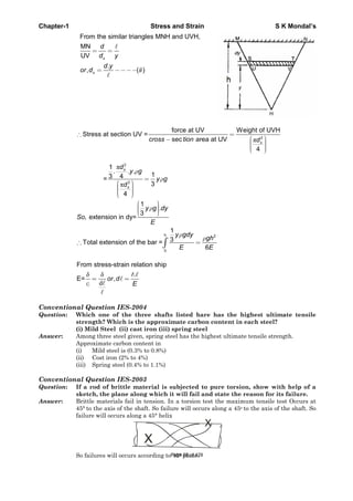
IAS-2. A rod of length 'l' and cross-section area ‘A’ rotates about an axis passing
through one end of the rod. The extension produced in the rod due to
centrifugal forces is (w is the weight of the rod per unit length and is the
angular velocity of rotation of the rod). [IAS 1994]
(a)
gE
wl2
(b)
gE
wl
3
32
(c)
gE
wl32
(d) 32
3
wl
gE
IAS-2. Ans. (b)
Page 36 of 429](https://image.slidesharecdn.com/strengthofmaterialsbyskmondal-130102103545-phpapp02-150924095946-lva1-app6891/85/Strengthofmaterialsbyskmondal-130102103545-phpapp02-36-320.jpg)
![Chapter-1 Stress and Strain S K Mondal’s
Elongation of a Taper Rod
IAS-3. A rod of length, " " tapers uniformly from a diameter ''D1' to a diameter ''D2' and
carries an axial tensile load of "P". The extension of the rod is (E represents the
modulus of elasticity of the material of the rod) [IAS-1996]
(a)
1 2
4 1P
ED D 1 2
4 1
( )
PE
b
D D
(c)
1 2
1
4
EP
D D
(d)
1 2
1
4
P
ED D
IAS-3. Ans. (a) The extension of the taper rod =
1 2
Pl
D D .E
4
Poisson’s ratio
IAS-4. In the case of an engineering material under unidirectional stress in the x-
direction, the Poisson's ratio is equal to (symbols have the usual meanings)
[IAS 1994, IES-2000]
(a)
x
y
(b)
x
y
(c)
x
y
(d)
x
y
IAS-4. Ans. (a)
IAS-5. Assertion (A): Poisson's ratio of a material is a measure of its ductility.
Reason (R): For every linear strain in the direction of force, Poisson's ratio of
the material gives the lateral strain in directions perpendicular to the
direction of force. [IAS-1999]
(a) Both A and R are individually true and R is the correct explanation of A
(b) Both A and R are individually true but R is not the correct explanation of A
(c) A is true but R is false
(d) A is false but R is true
IAS-5. ans. (d)
IAS-6. Assertion (A): Poisson's ratio is a measure of the lateral strain in all direction
perpendicular to and in terms of the linear strain. [IAS-1997]
Reason (R): The nature of lateral strain in a uni-axially loaded bar is opposite
to that of the linear strain.
(a) Both A and R are individually true and R is the correct explanation of A
(b) Both A and R are individually true but R is not the correct explanation of A
(c) A is true but R is false
(d) A is false but R is true
IAS-6. Ans. (b)
Elasticity and Plasticity
IAS-7. A weight falls on a plunger fitted in a container filled with oil thereby
producing a pressure of 1.5 N/mm2 in the oil. The Bulk Modulus of oil is 2800
N/mm2. Given this situation, the volumetric compressive strain produced in the
oil will be: [IAS-1997]
(a) 400 × 10-6 (b) 800 × 106 (c) 268 × 106 (d) 535 × 10-6
IAS-7. Ans. (d) Bulk modulus of elasticity (K) = 6
v
v
P P 1.5
or 535 10
K 2800
Relation between the Elastic Modulii
IAS-8. For a linearly elastic, isotropic and homogeneous material, the number of
elastic constants required to relate stress and strain is: [IAS 1994; IES-1998]
(a) Two (b) Three (c) Four (d) Six
IAS-8. Ans. (a)
Page 37 of 429](https://image.slidesharecdn.com/strengthofmaterialsbyskmondal-130102103545-phpapp02-150924095946-lva1-app6891/85/Strengthofmaterialsbyskmondal-130102103545-phpapp02-37-320.jpg)
![Chapter-1 Stress and Strain S K Mondal’s
IAS-9. The independent elastic constants for a homogenous and isotropic material are
(a) E, G, K, v (b) E, G, K (c) E, G, v (d) E, G [IAS-1995]
IAS-9. Ans. (d)
IAS-10. The unit of elastic modulus is the same as those of [IAS 1994]
(a) Stress, shear modulus and pressure (b) Strain, shear modulus and force
(c) Shear modulus, stress and force (d) Stress, strain and pressure.
IAS-10. Ans. (a)
IAS-11. Young's modulus of elasticity and Poisson's ratio of a material are 1.25 × 10⁵
MPa and 0.34 respectively. The modulus of rigidity of the material is:
[IAS 1994, IES-1995, 2001, 2002, 2007]
(a) 0.4025 × 10⁵ MPa (b) 0.4664 × 10⁵ MPa
(c) 0.8375 × 10⁵ MPa (d) 0.9469 × 10⁵ MPa
IAS-11. Ans.(b) )1(2GE or 1.25x105 = 2G(1+0.34) or G = 0.4664 × 10⁵ MPa
IAS-12. The Young's modulus of elasticity of a material is 2.5 times its modulus of
rigidity. The Posson's ratio for the material will be: [IAS-1997]
(a) 0.25 (b) 0.33 (c) 0.50 (d) 0.75
IAS-12. Ans. (a)
E E 2.5
E 2G 1 1 1 1 0.25
2G 2G 2
IAS-13. In a homogenous, isotropic elastic material, the modulus of elasticity E in
terms of G and K is equal to [IAS-1995, IES - 1992]
(a)
3
9
G K
KG
(b)
3
9
G K
KG
(c)
9
3
KG
G K
(d)
9
3
KG
K G
IAS-13. Ans. (c)
IAS-14. The Elastic Constants E and K are related as ( is the Poisson’s ratio)[IAS-1996]
(a) E = 2k (1 – 2 ) (b) E = 3k (1- 2 ) (c) E = 3k (1 + ) (d) E = 2K(1 + 2 )
IAS-14. Ans. (b) E = 2G (1 + ) = 3k (1- 2 )
IAS-15. For an isotropic, homogeneous and linearly elastic material, which obeys
Hooke's law, the number of independent elastic constant is: [IAS-2000]
(a) 1 (b) 2 (c) 3 (d) 6
IAS-15. Ans. (b) E, G, K and μ represent the elastic modulus, shear modulus, bulk modulus and
poisons ratio respectively of a ‘linearly elastic, isotropic and homogeneous material.’ To
express the stress – strain relations completely for this material; at least any two of the
four must be known.
9
2 1 3 1 3
3
KG
E G K
K G
IAS-16. The moduli of elasticity and rigidity of a material are 200 GPa and 80 GPa,
respectively. What is the value of the Poisson's ratio of the material? [IAS-2007]
(a) 0·30 (b) 0·26 (c) 0·25 (d) 0·24
IAS-16. Ans. (c) E = 2G (1+ ) or =
200
1 1 0.25
2 2 80
E
G
Stresses in compound strut
IAS-17. The reactions at the rigid supports at A and B for the bar loaded as shown in
the figure are respectively. [IES-2002; IAS-2003]
(a) 20/3 kN,10/3 Kn (b) 10/3 kN, 20/3 kN (c) 5 kN, 5 kN (d) 6 kN, 4 kN
Page 38 of 429](https://image.slidesharecdn.com/strengthofmaterialsbyskmondal-130102103545-phpapp02-150924095946-lva1-app6891/85/Strengthofmaterialsbyskmondal-130102103545-phpapp02-38-320.jpg)
![Chapter-1 Stress and Strain S K Mondal’s
IAS-17. Ans. (a) Elongation in AC = length reduction in CB
A BR 1 R 2
AE AE
And RA + RB = 10
Thermal effect
IAS-18. A steel rod 10 mm in diameter and 1m long is heated from 20°C to 120°C, E = 200
GPa and = 12 × 10-6 per °C. If the rod is not free to expand, the thermal stress
developed is: [IAS-2003, IES-1997, 2000, 2006]
(a) 120 MPa (tensile) (b) 240 MPa (tensile)
(c) 120 MPa (compressive) (d) 240 MPa (compressive)
IAS-18. Ans. (d) 6 3
E t 12 10 200 10 120 20 240MPa
It will be compressive as elongation restricted.
IAS-19. A. steel rod of diameter 1 cm and 1 m long is heated from 20°C to 120°C. Its
6
12 10 / K and E=200 GN/m2. If the rod is free to expand, the thermal
stress developed in it is: [IAS-2002]
(a) 12 × 104 N/m2 (b) 240 kN/m2 (c) zero (d) infinity
IAS-19. Ans. (c) Thermal stress will develop only if expansion is restricted.
IAS-20. Which one of the following pairs is NOT correctly matched? [IAS-1999]
(E = Young's modulus, = Coefficient of linear expansion, T = Temperature
rise, A = Area of cross-section, l= Original length)
(a) Temperature strain with permitted expansion ….. ( Tl )
(b) Temperature stress ….. TE
(c) Temperature thrust ….. TEA
(d) Temperature stress with permitted expansion …..
( )E Tl
l
IAS-20. Ans. (a) Dimensional analysis gives (a) is wrong
Impact loading
IAS-21. Match List I with List II and select the correct answer using the codes given
below the lists: [IAS-1995]
List I (Property) List II (Testing Machine)
A. Tensile strength 1. Rotating Bending Machine
B. Impact strength 2. Three-Point Loading Machine
C. Bending strength 3. Universal Testing Machine
D. Fatigue strength 4. Izod Testing Machine
Codes: A B C D A B C D
(a) 4 3 2 1 (b) 3 2 1 4
(c) 2 1 4 3 (d) 3 4 2 1
IAS-21. Ans. (d)
Page 39 of 429](https://image.slidesharecdn.com/strengthofmaterialsbyskmondal-130102103545-phpapp02-150924095946-lva1-app6891/85/Strengthofmaterialsbyskmondal-130102103545-phpapp02-39-320.jpg)
![Chapter-1 Stress and Strain S K Mondal’s
Tensile Test
IAS-22. A mild steel specimen is tested in tension up to fracture in a Universal Testing
Machine. Which of the following mechanical properties of the material can be
evaluated from such a test? [IAS-2007]
1. Modulus of elasticity 2. Yield stress 3. Ductility
4. Tensile strength 5. Modulus of rigidity
Select the correct answer using the code given below:
(a) 1, 3, 5 and 6 (b) 2, 3, 4 and 6 (c) 1, 2, 5 and 6 (d) 1, 2, 3 and 4
IAS-22. Ans. (d)
IAS-23. In a simple tension test, Hooke's law is valid upto the [IAS-1998]
(a) Elastic limit (b) Limit of proportionality (c) Ultimate stress (d) Breaking point
IAS-23. Ans. (b)
IAS-24. Lueder' lines on steel specimen under simple tension test is a direct indication
of yielding of material due to slip along the plane [IAS-1997]
(a) Of maximum principal stress (b) Off maximum shear
(c) Of loading (d) Perpendicular to the direction of loading
IAS-24. Ans. (b)
IAS-25. The percentage elongation of a material as obtained from static tension test
depends upon the [IAS-1998]
(a) Diameter of the test specimen (b) Gauge length of the specimen
(c) Nature of end-grips of the testing machine (d) Geometry of the test specimen
IAS-25. Ans. (b)
IAS-26. Match List-I (Types of Tests and Materials) with List-II (Types of Fractures)
and select the correct answer using the codes given below the lists:
List I List-II [IES-2002; IAS-2004]
(Types of Tests and Materials) (Types of Fractures)
A. Tensile test on CI 1. Plain fracture on a transverse plane
B. Torsion test on MS 2. Granular helecoidal fracture
C. Tensile test on MS 3. Plain granular at 45° to the axis
D. Torsion test on CI 4. Cup and Cone
5. Granular fracture on a transverse plane
Codes: A B C D A B C D
(a) 4 2 3 1 (c) 4 1 3 2
(b) 5 1 4 2 (d) 5 2 4 1
IAS-26. Ans. (d)
IAS-27. Assertion (A): For a ductile material stress-strain curve is a straight line up to
the yield point. [IAS-2003]
Reason (R): The material follows Hooke's law up to the point of proportionality.
(a) Both A and R are individually true and R is the correct explanation of A
(b) Both A and R are individually true but R is not the correct explanation of A
(c) A is true but R is false
(d) A is false but R is true
IAS-27. Ans. (d)
IAS-28. Assertion (A): Stress-strain curves for brittle material do not exhibit yield
point. [IAS-1996]
Reason (R): Brittle materials fail without yielding.
(a) Both A and R are individually true and R is the correct explanation of A
(b) Both A and R are individually true but R is NOT the correct explanation of A
(c) A is true but R is false
(d) A is false but R is true
IAS-28. Ans. (a) Up to elastic limit.
Page 40 of 429](https://image.slidesharecdn.com/strengthofmaterialsbyskmondal-130102103545-phpapp02-150924095946-lva1-app6891/85/Strengthofmaterialsbyskmondal-130102103545-phpapp02-40-320.jpg)
![Chapter-1 Stress and Strain S K Mondal’s
IAS-29. Match List I (Materials) with List II (Stress-Strain curves) and select the
correct answer using the codes given below the Lists: [IAS-2001]
Codes: A B C D A B C D
(a) 3 1 4 1 (b) 3 2 4 2
(c) 2 4 3 1 (d) 4 1 3 2
IAS-29. Ans. (b)
IAS-30. The stress-strain curve of an ideal elastic strain hardening material will be as
[IAS-1998]
IAS-30. Ans. (d)
IAS-31. An idealised stress-strain curve for a perfectly plastic material is given by
[IAS-1996]
IAS-31. Ans. (a)
IAS-32. Match List I with List II and select the correct answer using the codes given
below the Lists: [IAS-2002]
List I List II
A. Ultimate strength 1. Internal structure
Page 41 of 429](https://image.slidesharecdn.com/strengthofmaterialsbyskmondal-130102103545-phpapp02-150924095946-lva1-app6891/85/Strengthofmaterialsbyskmondal-130102103545-phpapp02-41-320.jpg)
![Chapter-1 Stress and Strain S K Mondal’s
B. Natural strain 2. Change of length per unit instantaneous length
C. Conventional strain 3. Change of length per unit gauge length
D. Stress 4. Load per unit area
Codes: A B C D A B C D
(a) 1 2 3 4 (b) 4 3 2 1
(c) 1 3 2 4 (d) 4 2 3 1
IAS-32. Ans. (a)
IAS-33. What is the cause of failure of a short MS strut under an axial load? [IAS-2007]
(a) Fracture stress (b) Shear stress (c) Buckling (d) Yielding
IAS-33. Ans. (d) In compression tests of ductile materials fractures is seldom obtained.
Compression is accompanied by lateral expansion and a compressed cylinder ultimately
assumes the shape of a flat disc.
IAS-34. Match List I with List II and select the correct answer using the codes given
the lists: [IAS-1995]
List I List II
A. Rigid-Perfectly plastic
B. Elastic-Perfectly plastic
C. Rigid-Strain hardening
D. Linearly elastic
Codes: A B C D A B C D
(a) 3 1 4 2 (b) 1 3 2 4
(c) 3 1 2 4 (d) 1 3 4 2
IAS-34. Ans. (a)
IAS-35. Which one of the following materials is highly elastic? [IAS-1995]
(a) Rubber (b) Brass (c) Steel (d) Glass
IAS-35. Ans. (c) Steel is the highly elastic material because it is deformed least on loading, and
regains its original from on removal of the load.
IAS-36. Assertion (A): Hooke's law is the constitutive law for a linear elastic material.
Reason (R) Formulation of the theory of elasticity requires the hypothesis that there
exists a unique unstressed state of the body, to which the body returns
whenever all the forces are removed. [IAS-2002]
(a) Both A and R are individually true and R is the correct explanation of A
(b) Both A and R are individually true but R is not the correct explanation of A
(c) A is true but R is false
(d) A is false but R is true
IAS-36. Ans. (a)
IAS-37. Consider the following statements: [IAS-2002]Page 42 of 429](https://image.slidesharecdn.com/strengthofmaterialsbyskmondal-130102103545-phpapp02-150924095946-lva1-app6891/85/Strengthofmaterialsbyskmondal-130102103545-phpapp02-42-320.jpg)
![Chapter-1 Stress and Strain S K Mondal’s
1. There are only two independent elastic constants.
2. Elastic constants are different in orthogonal directions.
3. Material properties are same everywhere.
4. Elastic constants are same in all loading directions.
5. The material has ability to withstand shock loading.
Which of the above statements are true for a linearly elastic, homogeneous and
isotropic material?
(a) 1, 3, 4 and 5 (b) 2, 3 and 4 (c) 1, 3 and 4 (d) 2 and 5
IAS-37. Ans. (a)
IAS-38. Which one of the following pairs is NOT correctly matched? [IAS-1999]
(a) Uniformly distributed stress …. Force passed through the centroid of the
cross-section
(b) Elastic deformation …. Work done by external forces during
deformation is dissipated fully as heat
(c) Potential energy of strain …. Body is in a state of elastic deformation
(d) Hooke's law …. Relation between stress and strain
IAS-38. Ans. (b)
IAS-39. A tensile bar is stressed to 250 N/mm2 which is beyond its elastic limit. At this
stage the strain produced in the bar is observed to be 0.0014. If the modulus of
elasticity of the material of the bar is 205000 N/mm2 then the elastic component
of the strain is very close to [IAS-1997]
(a) 0.0004 (b) 0.0002 (c) 0.0001 (d) 0.00005
IAS-39. Ans. (b)
Page 43 of 429](https://image.slidesharecdn.com/strengthofmaterialsbyskmondal-130102103545-phpapp02-150924095946-lva1-app6891/85/Strengthofmaterialsbyskmondal-130102103545-phpapp02-43-320.jpg)
![Chapter-1 Stress and Strain S K Mondal’s
Previous Conventional Questions with Answers
Conventional Question IES-2010
Q. If a load of 60 kN is applied to a rigid
bar suspended by 3 wires as shown
in the above figure what force will
be resisted by each wire?
The outside wires are of Al, cross-
sectional area 300 mm2 and length 4
m. The central wire is steel with area
200 mm2 and length 8 m.
Initially there is no slack in the
wires 5 2
E 2 10 N / mm for Steel
5 2
0.667 10 N / mm for Aluminum
[2 Marks]
Ans.
FA1
FSt
Aluminium wire
Steel wire
FA1
60kN
P 60 kN
2
A1 A1a 300mm l 4m
2
st sta 200mm l 8m
5 2
A1E 0.667 10 N / mm
5 2
stE 2 10 N / mm
Force balance along vertical direction
A1 st2F F 60 kN (1)
Elongation will be same in all wires because rod is rigid remain horizontal after
loading
st stA1 A1
Al Al st st
F .lF l
a .E a .E
(2)
stA1
5 5
F 8F 4
300 0.667 10 200 2 10
A1 stF 1.0005 F (3)
Page 44 of 429](https://image.slidesharecdn.com/strengthofmaterialsbyskmondal-130102103545-phpapp02-150924095946-lva1-app6891/85/Strengthofmaterialsbyskmondal-130102103545-phpapp02-44-320.jpg)
![Chapter-1 Stress and Strain S K Mondal’s
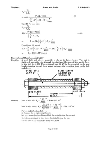
Question: List at least two factors that promote transition from ductile to brittle
fracture.
Answer: (i) With the grooved specimens only a small reduction in area took place, and the
appearance of the facture was like that of brittle materials.
(ii) By internal cavities, thermal stresses and residual stresses may combine with
the effect of the stress concentration at the cavity to produce a crack. The
resulting fracture will have the characteristics of a brittle failure without
appreciable plastic flow, although the material may prove ductile in the usual
tensile tests.
Conventional Question IES-1999
Question: Distinguish between creep and fatigue.
Answer: Fatigue is a phenomenon associated with variable loading or more precisely to cyclic
stressing or straining of a material, metallic, components subjected to variable loading
get fatigue, which leads to their premature failure under specific conditions.
When a member is subjected to a constant load over a long period of time it undergoes
a slow permanent deformation and this is termed as ''Creep''. This is dependent on
temperature.
Conventional Question IES-2008
Question: What different stresses set-up in a bolt due to initial tightening, while used as
a fastener? Name all the stresses in detail.
Answer: (i) When the nut is initially tightened there will be some elongation in the bolt so
tensile stress will develop.
(ii) While it is tightening a torque across some shear stress. But when tightening will
be completed there should be no shear stress.
Conventional Question IES-2008
Question: A Copper rod 6 cm in diameter is placed within a steel tube, 8 cm external
diameter and 6 cm internal diameter, of exactly the same length. The two
pieces are rigidly fixed together by two transverse pins 20 mm in diameter,
one at each end passing through both rod and the tube.
Calculated the stresses induced in the copper rod, steel tube and the pins if
the temperature of the combination is raised by 50oC.
[Take ES=210 GPa, 0.0000115/o
s C ; Ec=105 GPa, 0.000017 /o
c C ]
Answer:
( )c s
c s
c s
t
E E
22
2 3 2
c
6
Area of copper rod(A ) = 2.8274 10
4 4 100
d
m m
2 22
2 3 28 6
Area of steel tube (A ) = 2.1991 10
4 4 100 100
s
d
m m
in temperature, 50o
Rise t C
cFree expansion of copper bar= L t
Free expansion of steel tube = sL tPage 46 of 429](https://image.slidesharecdn.com/strengthofmaterialsbyskmondal-130102103545-phpapp02-150924095946-lva1-app6891/85/Strengthofmaterialsbyskmondal-130102103545-phpapp02-46-320.jpg)
![Chapter-1 Stress and Strain S K Mondal’s
Conventional Question IAS-1995
Question: The steel bolt shown in Figure has a thread pitch of 1.6 mm. If the nut is
initially tightened up by hand so as to cause no stress in the copper spacing
tube, calculate the stresses induced in the tube and in the bolt if a spanner is
then used to turn the nut through 90°.Take Ec and Es as 100 GPa and 209 GPa
respectively.
Answer: Given: p = 1.6 mm, Ec= 100 GPa ; Es = 209 CPa.
Stresses induced in the tube and the bolt, c s, :
2
5 2
s
2 2
5 2
s
10
A 7.584 10 m
4 1000
18 12
A 14.14 10 m
4 1000 1000
Tensile force on steel bolt, Ps = compressive force in copper tube, Pc = P
Also, Increase in length of bolt + decrease in length of tube = axial displacement of nut
3
s c
3
s c
s s c c
3
5 9 5 9
s c
90
i,e l l 1.6 0.4mm 0.4 10 m
360
Pl Pl
or 0.4 10 l l l
A E A E
100 1 1
or P 0.4 10
1000 7.854 10 209 10 14.14 10 100 10
or P 30386N
P P
386.88MPa and 214.89MPa
A A
Conventional Question AMIE-1997
Question: A steel wire 2 m long and 3 mm in diameter is extended by 0·75 mm when a
weight W is suspended from the wire. If the same weight is suspended from a
brass wire, 2·5 m long and 2 mm in diameter, it is elongated by 4 -64 mm.
Determine the modulus of elasticity of brass if that of steel be 2.0 × 10⁵ N /
mm2
Answer: Given, sl 2 m, ds = 3 mm, sl 0·75 mm; Es = 2·0 × 105 N / mm2; bl 2.5 m, db
=2 mm bl 4.64mm and let modulus of elasticity of brass = Eb
Hooke's law gives,
Pl
l
AE
[Symbol has usual meaning]
Case I: For steel wire:
Page 51 of 429](https://image.slidesharecdn.com/strengthofmaterialsbyskmondal-130102103545-phpapp02-150924095946-lva1-app6891/85/Strengthofmaterialsbyskmondal-130102103545-phpapp02-51-320.jpg)
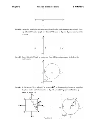
![Chapter-2 Principal Stress and Strain S K Mondal’s
Step-VI: Calculation, Draw a perpendicular PQ and PR where PQ = and PR = n
OC and MC = CL = CP =
2 2
PR = cos 2
2 2
PQ = = CPsin 2 = sin 2
2
x y x y
x y x y
x y
n
[Note: In the examination you only draw final figure (which is in Step-V) and follow the
procedure step by step so that no mistakes occur.]
Construction of Mohr’s circle for unlike stresses (when x and y are opposite in sign)
Follow the same steps which we followed for construction for ‘like stresses’ and finally will get
the figure shown below.
Note: For construction of Mohr’s circle for principal stresses when ( 1and 2 is known) then follow
the same steps of Constant of Mohr’s circle for Bi-axial stress (when only x and y known) just
change the 1x and 2y
Page 70 of 429](https://image.slidesharecdn.com/strengthofmaterialsbyskmondal-130102103545-phpapp02-150924095946-lva1-app6891/85/Strengthofmaterialsbyskmondal-130102103545-phpapp02-70-320.jpg)
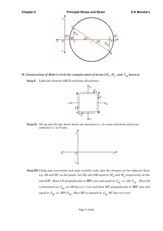
![Chapter-2 Principal Stress and Strain S K Mondal’s
Step-IV: Join ST and it will cut oσ axis at C. With C as centre and CS or CT as radius, draw
circle. It is the Mohr’s circle.
Step-V: At the centre draw a line CP at an angle 2θ in the same direction as the normal to the
plane makes with the direction of xσ .
Step-VI: Calculation, Draw a perpendicular PQ and PR where PQ = τ and PR = σn
Centre, OC =
2
x yσ σ+
Radius CS = ( ) ( )
2
2 2 2CL LS CT= CP
2
yx
xy
σ σ
τ
−⎛ ⎞
+ = + =⎜ ⎟⎜ ⎟
⎝ ⎠
PR cos 2 sin 2
2 2
PQ sin2 cos2 .
2
x y x y
n xy
x y
xy
σ σ σ σ
σ θ τ θ
σ σ
τ θ τ θ
+ −
= = + +
−
= = −
[Note: In the examination you only draw final figure (which is in Step-V) and follow the
procedure step by step so that no mistakes occur.]
PDF created with pdfFactory Pro trial version www.pdffactory.com
Page 72 of 429](https://image.slidesharecdn.com/strengthofmaterialsbyskmondal-130102103545-phpapp02-150924095946-lva1-app6891/85/Strengthofmaterialsbyskmondal-130102103545-phpapp02-72-320.jpg)

![Chapter-2 Principal Stress and Strain S K Mondal’s
x
x
E
;
x
y x
E
; and
x
z x
E
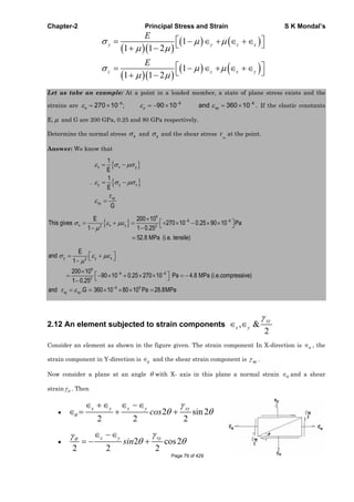
1-D state of strain or Uni-axial state of strain
0 0
0 0 0 0
0 0 0 0 0 0
0 0 0 0
0 0
x
x y
x
ij x y
x y
x
E p
q
E
q
E
2-D Strain ( 0)z
(i)
1
x x y
E
1
y y x
E
z x y
E
[Where, , ,x y z are strain component in X, Y, and Z axis respectively]
(ii)
2
1
x x y
E
2
1
y y x
E
3-D Strain
(i)
1
x x y z
E
1
y y z x
E
1
z z x y
E
(ii) 1
1 1 2
x x y z
E
Page 78 of 429](https://image.slidesharecdn.com/strengthofmaterialsbyskmondal-130102103545-phpapp02-150924095946-lva1-app6891/85/Strengthofmaterialsbyskmondal-130102103545-phpapp02-78-320.jpg)
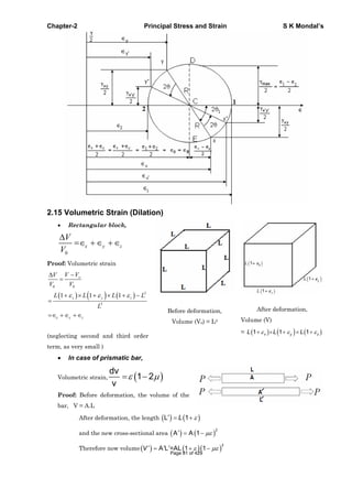
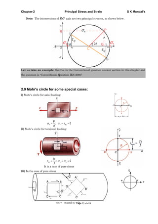
![Chapter-2 Principal Stress and Strain S K Mondal’s
2
AL 1 1 ALV V -V
1 2
V V AL
V
1 2
V
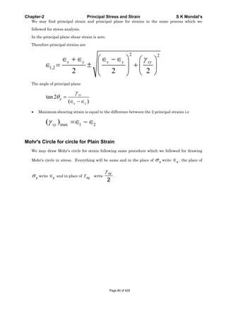
Thin Cylindrical vessel
1=Longitudinal strain = 1 2
1 2
2
pr
E E Et
2 =Circumferential strain = 2 1
2
2
pr
E E Et
1 22 [5 4 ]
2o
V pr
V Et
Thin Spherical vessels
1 2 [1 ]
2
pr
Et
0
3
3 [1 ]
2
V pr
V Et
In case of pure shear
x y
Therefore
x
y
z
1
E
1
E
0
x y z
dv
Therefore 0
v
v
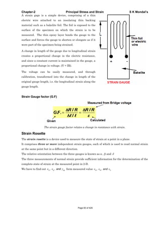
2.16 Measurement of Strain
Unlike stress, strain can be measured directly. The most common way of measuring strain is by use
of the Strain Gauge.
Strain Gauge
Page 82 of 429](https://image.slidesharecdn.com/strengthofmaterialsbyskmondal-130102103545-phpapp02-150924095946-lva1-app6891/85/Strengthofmaterialsbyskmondal-130102103545-phpapp02-82-320.jpg)
![Chapter-2 Principal Stress and Strain S K Mondal’s
OBJECTIVE QUESTIONS (GATE, IES, IAS)
Previous 20-Years GATE Questions
Stresses due to Pure Shear
GATE-1. A block of steel is loaded by a tangential force on its top surface while the
bottom surface is held rigidly. The deformation of the block is due to
[GATE-1992]
(a) Shear only (b) Bending only (c) Shear and bending (d) Torsion
GATE-1. Ans. (a) It is the definition of shear stress. The force is applied tangentially it is not a
point load so you cannot compare it with a cantilever with a point load at its free end.
GATE-2. A shaft subjected to torsion experiences a pure shear stress on the surface.
The maximum principal stress on the surface which is at 45° to the axis will
have a value [GATE-2003]
(a) cos 45° (b) 2 cos 45° (c) cos2 45° (d) 2 sin 45° cos 45°
GATE-2. Ans. (d)
x y x y
n xycos2 sin2
2 2
Here o
x 2 xy0, , 45
GATE-3. The number of components in a stress tensor defining stress at a point in three
dimensions is: [GATE-2002]
(a) 3 (b) 4 (c) 6 (d) 9
GATE-3. Ans. (d) It is well known that,
xy yx, xz zx yz zy
x y z xy yz zx
and
so that the state of stress at a point is given by six components , , and , ,
Principal Stress and Principal Plane
GATE-4. A body is subjected to a pure tensile stress of 100 units. What is the maximum
shear produced in the body at some oblique plane due to the above? [IES-2006]
(a) 100 units (b) 75 units (c) 50 units (d) 0 unit
GATE-4. Ans. (c) 1 2
max
100 0
50 units.
2 2
GATE-5. In a strained material one of the principal stresses is twice the other. The
maximum shear stress in the same case is max .Then, what is the value of the
maximum principle stress? [IES 2007]
(a) max (b) 2 max (c) 4 max (d) 8 max
GATE-5. Ans. (c)
2
21
max , 21 2 or
2
2
max or max2 2 or 21 2 = max4
GATE-6. A material element subjected to a plane state of stress such that the maximum
shear stress is equal to the maximum tensile stress, would correspond to
[IAS-1998]
Page 85 of 429](https://image.slidesharecdn.com/strengthofmaterialsbyskmondal-130102103545-phpapp02-150924095946-lva1-app6891/85/Strengthofmaterialsbyskmondal-130102103545-phpapp02-85-320.jpg)
![Chapter-2 Principal Stress and Strain S K Mondal’s
GATE-6. Ans. (d) 1 2 1 1
max 1
( )
2 2
GATE-7. A solid circular shaft is subjected to a maximum shearing stress of 140 MPs.
The magnitude of the maximum normal stress developed in the shaft is:
[IAS-1995]
(a) 140 MPa (b) 80 MPa (c) 70 MPa (d) 60 MPa
GATE-7. Ans. (a) 1 2
max
2
Maximum normal stress will developed if 1 2
GATE-8. The state of stress at a point in a loaded member is shown in the figure. The
magnitude of maximum shear stress is [1MPa = 10 kg/cm2] [IAS 1994]
(a) 10 MPa (b) 30 MPa (c) 50 MPa (d) 100MPa
GATE-8. Ans. (c)
2
2
max
2
xy
yx
=
2
2
30
2
4040
= 50 MPa
GATE-9. A solid circular shaft of diameter 100 mm is subjected to an axial stress of 50
MPa. It is further subjected to a torque of 10 kNm. The maximum principal
stress experienced on the shaft is closest to [GATE-2008]
(a) 41 MPa (b) 82 MPa (c) 164 MPa (d) 204 MPa
GATE-9. Ans. (b) Shear Stress ( )= MPaPa
d
T
93.50
)1.0(
100001616
33
Maximum principal Stress =
2
2
22
bb
=82 MPa
GATE-10. In a bi-axial stress problem, the stresses in x and y directions are ( x = 200 MPa
and y =100 MPa. The maximum principal stress in MPa, is: [GATE-2000]
(a) 50 (b) 100 (c) 150 (d) 200
GATE-10. Ans. (d)
2
x y x y 2
1 xy xyif 0
2 2
Page 86 of 429](https://image.slidesharecdn.com/strengthofmaterialsbyskmondal-130102103545-phpapp02-150924095946-lva1-app6891/85/Strengthofmaterialsbyskmondal-130102103545-phpapp02-86-320.jpg)
![Chapter-2 Principal Stress and Strain S K Mondal’s
2
x y x y
x
2 2
GATE-11. The maximum principle stress for the stress
state shown in the figure is
(a) (b) 2
(c) 3 (d) 1.5
[GATE-2001]
GATE-11. Ans. (b) x y xy, ,
2
2x y x y 2 2
1 xymax
0 2
2 2 2
GATE-12. The normal stresses at a point are x = 10 MPa and, y = 2 MPa; the shear stress
at this point is 4MPa. The maximum principal stress at this point is:
[GATE-1998]
(a) 16 MPa (b) 14 MPa (c) 11 MPa (d) 10 MPa
GATE-12. Ans. (c)
2
x y x y 2
1 xy
2 2
2
210 2 10 2
4 11.66 MPa
2 2
GATE-13. In a Mohr's circle, the radius of the circle is taken as: [IES-2006; GATE-1993]
(a)
2
2
2
x y
xy (b)
2
2
2
x y
xy
(c)
2
2
2
x y
xy (d)
2 2
x y xy
Where, x and y are normal stresses along x and y directions respectively and xy is the
shear stress.
GATE-13. Ans. (a)
GATE-14. A two dimensional fluid element rotates like a rigid body. At a point within the
element, the pressure is 1 unit. Radius of the Mohr's circle, characterizing the
state of stress at that point, is: [GATE-2008]
(a) 0.5 unit (b) 0 unit (c) 1 unit (d) 2 units
GATE-14. Ans. (b)
Page 87 of 429](https://image.slidesharecdn.com/strengthofmaterialsbyskmondal-130102103545-phpapp02-150924095946-lva1-app6891/85/Strengthofmaterialsbyskmondal-130102103545-phpapp02-87-320.jpg)
![Chapter-2 Principal Stress and Strain S K Mondal’s
GATE-15. The Mohr's circle of plane stress
for a point in a body is shown.
The design is to be done on the
basis of the maximum shear
stress theory for yielding. Then,
yielding will just begin if the
designer chooses a ductile
material whose yield strength is:
(a) 45 MPa (b) 50 MPa
(c) 90 MPa (d) 100 MPa [GATE-2005]
GATE-15. Ans. (c)
1 2
y1 2
max
1 2 y y
Given 10 MPa, 100 MPa
Maximum shear stresstheory give
2 2
or 10 ( 100) 90MPa
GATE-16. The figure shows the state of
stress at a certain point in a
stressed body. The magnitudes of
normal stresses in the x and y
direction are 100MPa and 20 MPa
respectively. The radius of
Mohr's stress circle representing
this state of stress is:
(a) 120 (b) 80
(c) 60 (d) 40
[GATE-2004]
GATE-16. Ans. (c)
x y
x y
100MPa, 20MPa
100 20
Radius of Mohr 'scircle 60
2 2
Data for Q17–Q18 are given below. Solve the problems and choose correct answers.
[GATE-2003]
The state of stress at a point "P" in a two dimensional loading is such that the Mohr's
circle is a point located at 175 MPa on the positive normal stress axis.
GATE-17. Determine the maximum and minimum principal stresses respectively from the
Mohr's circle
(a) + 175 MPa, –175MPa (b) +175 MPa, +175 MPa
(c) 0, –175 MPa (d) 0, 0
GATE-17. Ans. (b)
1 2 x y 175 MPa
GATE-18. Determine the directions of maximum and minimum principal stresses at the
point “P” from the Mohr's circle [GATE-2003]Page 88 of 429](https://image.slidesharecdn.com/strengthofmaterialsbyskmondal-130102103545-phpapp02-150924095946-lva1-app6891/85/Strengthofmaterialsbyskmondal-130102103545-phpapp02-88-320.jpg)
![Chapter-2 Principal Stress and Strain S K Mondal’s
(a) 0, 90° (b) 90°, 0 (c) 45°, 135° (d) All directions
GATE-18. Ans. (d) From the Mohr’s circle it will give all directions.
Principal strains
GATE-19. If the two principal strains at a point are 1000 × 10-6 and -600 × 10-6, then the
maximum shear strain is: [GATE-1996]
(a) 800 × 10-6 (b) 500 × 10-6 (c) 1600 × 10-6 (d) 200 × 10-6
GATE-19. Ans. (c) Shear strain 6 6
max mine e 1000 600 10 1600 10
Previous 20-Years IES Questions
Stresses due to Pure Shear
IES-1. If a prismatic bar be subjected to an axial tensile stress , then shear stress
induced on a plane inclined at with the axis will be: [IES-1992]
2 2
a sin 2 b cos2 c cos d sin
2 2 2 2
IES-1. Ans. (a)
IES-2. In the case of bi-axial state of normal stresses, the normal stress on 45° plane is
equal to [IES-1992]
(a) The sum of the normal stresses (b) Difference of the normal stresses
(c) Half the sum of the normal stresses (d) Half the difference of the normal stresses
IES-2. Ans. (c)
x y x y
n xycos2 sin2
2 2
x yo
xy nAt 45 and 0;
2
IES-3. In a two-dimensional problem, the state of pure shear at a point is
characterized by [IES-2001]
(a) 0x y xyand (b) 0x y xyand
(c) 2 0x y xyand (d) 0.5 0x y xyand
IES-3. Ans. (b)
IES-4. Which one of the following Mohr’s circles represents the state of pure shear?
[IES-2000]
IES-4. Ans. (c)
Page 89 of 429](https://image.slidesharecdn.com/strengthofmaterialsbyskmondal-130102103545-phpapp02-150924095946-lva1-app6891/85/Strengthofmaterialsbyskmondal-130102103545-phpapp02-89-320.jpg)
![Chapter-2 Principal Stress and Strain S K Mondal’s
IES-5. For the state of stress of pure shear the strain energy stored per unit volume
in the elastic, homogeneous isotropic material having elastic constants E and
will be: [IES-1998]
(a)
2
1
E
(b)
2
1
2E
(c)
2
2
1
E
(d)
2
2
2E
IES-5. Ans. (a) 1 2 3, , 0
22 21 1
U 2 V V
2E E
IES-6. Assertion (A): If the state at a point is pure shear, then the principal planes
through that point making an angle of 45° with plane of shearing stress carries
principal stresses whose magnitude is equal to that of shearing stress.
Reason (R): Complementary shear stresses are equal in magnitude, but
opposite in direction. [IES-1996]
(a) Both A and R are individually true and R is the correct explanation of A
(b) Both A and R are individually true but R is NOT the correct explanation of A
(c) A is true but R is false
(d) A is false but R is true
IES-6. Ans. (b)
IES-7. Assertion (A): Circular shafts made of brittle material fail along a helicoidally
surface inclined at 45° to the axis (artery point) when subjected to twisting
moment. [IES-1995]
Reason (R): The state of pure shear caused by torsion of the shaft is equivalent
to one of tension at 45° to the shaft axis and equal compression in the
perpendicular direction.
(a) Both A and R are individually true and R is the correct explanation of A
(b) Both A and R are individually true but R is NOT the correct explanation of A
(c) A is true but R is false
(d) A is false but R is true
IES-7. Ans. (a) Both A and R are true and R is correct explanation for A.
IES-8. A state of pure shear in a biaxial state of stress is given by [IES-1994]
(a)
1
2
0
0
(b)
1
1
0
0
(c)
x xy
yx y
(d) None of the above
IES-8. Ans. (b) 1 2 3, , 0
IES-9. The state of plane stress in a plate of 100 mm thickness is given as [IES-2000]
xx = 100 N/mm2, yy = 200 N/mm2, Young's modulus = 300 N/mm2, Poisson's ratio
= 0.3. The stress developed in the direction of thickness is:
(a) Zero (b) 90 N/mm2 (c) 100 N/mm2 (d) 200 N/mm2
IES-9. Ans. (a)
IES-10. The state of plane stress at a point is described by and 0x y xy . The
normal stress on the plane inclined at 45° to the x-plane will be: [IES-1998]
a b 2 c 3 d 2
IES-10. Ans. (a)
x y x y
n xycos2 sin2
2 2
IES-11. Consider the following statements: [IES-1996, 1998]
State of stress in two dimensions at a point in a loaded component can be
completely specified by indicating the normal and shear stresses on
1. A plane containing the point
2. Any two planes passing through the point
3. Two mutually perpendicular planes passing through the pointPage 90 of 429](https://image.slidesharecdn.com/strengthofmaterialsbyskmondal-130102103545-phpapp02-150924095946-lva1-app6891/85/Strengthofmaterialsbyskmondal-130102103545-phpapp02-90-320.jpg)
![Chapter-2 Principal Stress and Strain S K Mondal’s
Of these statements
(a) 1, and 3 are correct (b) 2 alone is correct
(c) 1 alone is correct (d) 3 alone is correct
IES-11. Ans. (d)
Principal Stress and Principal Plane
IES-12. A body is subjected to a pure tensile stress of 100 units. What is the maximum
shear produced in the body at some oblique plane due to the above? [IES-2006]
(a) 100 units (b) 75 units (c) 50 units (d) 0 unit
IES-12. Ans. (c) 1 2
max
100 0
50 units.
2 2
IES-13. In a strained material one of the principal stresses is twice the other. The
maximum shear stress in the same case is max . Then, what is the value of the
maximum principle stress? [IES 2007]
(a) max (b) 2 max (c) 4 max (d) 8 max
IES-13. Ans. (c)
2
21
max , 21 2 or
2
2
max or max2 2 or 21 2 = max4
IES-14. In a strained material, normal stresses on two mutually perpendicular planes
are x and y (both alike) accompanied by a shear stress xy One of the principal
stresses will be zero, only if [IES-2006]
(a)
2
x y
xy (b) xy x y (c) xy x y (d)
2 2
xy x y
IES-14. Ans. (c)
2
x y x y 2
1,2 xy
2 2
2
x y x y 2
2 xy
2 2
x y x y 2
xy xy x y
if 0
2 2
or or
2 2
IES-15. The principal stresses 1, 2 and 3 at a point respectively are 80 MPa, 30 MPa
and –40 MPa. The maximum shear stress is: [IES-2001]
(a) 25 MPa (b) 35 MPa (c) 55 MPa (d) 60 MPa
IES-15. Ans. (d) 1 2
max
80 ( 40)
60
2 2
MPa
IES-16. Plane stress at a point in a body is defined by principal stresses 3 and . The
ratio of the normal stress to the maximum shear stresses on the plane of
maximum shear stress is: [IES-2000]
(a) 1 (b) 2 (c) 3 (d) 4
IES-16. Ans. (b)
xy
x y
2
tan2 0
1 2
max
3
2 2
Major principal stress on the plane of maximum shear = 1
3
2
2
Page 91 of 429](https://image.slidesharecdn.com/strengthofmaterialsbyskmondal-130102103545-phpapp02-150924095946-lva1-app6891/85/Strengthofmaterialsbyskmondal-130102103545-phpapp02-91-320.jpg)
![Chapter-2 Principal Stress and Strain S K Mondal’s
IES-17. Principal stresses at a point in plane stressed element are
2
500kg/cmx y .
Normal stress on the plane inclined at 45o to x-axis will be: [IES-1993]
(a) 0 (b) 500 kg/cm2 (c) 707 kg/cm2 (d) 1000 kg/cm2
IES-17. Ans. (b) When stresses are alike, then normal stress n on plane inclined at angle 45° is
2 2
2 2 21 1 1 1
cos sin 500 500kg/cm
2 22 2
n y x y x
IES-18. If the principal stresses corresponding to a two-dimensional state of stress are
1 and 2 is greater than 2 and both are tensile, then which one of the
following would be the correct criterion for failure by yielding, according to
the maximum shear stress criterion? [IES-1993]
1 2 1 2
1( ) ( ) ( ) ( ) 2
2 2 2 2 2 2
yp yp yp
ypa b c d
IES-18. Ans. (a)
IES-19. For the state of plane stress.
Shown the maximum and
minimum principal stresses are:
(a) 60 MPa and 30 MPa
(b) 50 MPa and 10 MPa
(c) 40 MPa and 20 MPa
(d) 70 MPa and 30 MPa
[IES-1992]
IES-19. Ans. (d)
2
x y x y 2
1,2 xy
2 2
2
2
1,2
50 ( 10) 50 10
40
2 2
max min70 and 30
IES-20. Normal stresses of equal magnitude p, but of opposite signs, act at a point of a
strained material in perpendicular direction. What is the magnitude of the
resultant normal stress on a plane inclined at 45° to the applied stresses?
[IES-2005]
(a) 2 p (b) p/2 (c) p/4 (d) Zero
IES-20. Ans. (d)
x y x y
x cos2
2 2
n
P P P P
cos2 45 0
2 2
IES-21. A plane stressed element is subjected to the state of stress given by
2
100kgf/cmx xy and y = 0. Maximum shear stress in the element is equal
to [IES-1997]
2 2 2 2
a 50 3 kgf/cm b 100kgf/cm c 50 5 kgf/cm d 150kgf/cm
Page 92 of 429](https://image.slidesharecdn.com/strengthofmaterialsbyskmondal-130102103545-phpapp02-150924095946-lva1-app6891/85/Strengthofmaterialsbyskmondal-130102103545-phpapp02-92-320.jpg)
![Chapter-2 Principal Stress and Strain S K Mondal’s
IES-21. Ans. (c)
2
2
1,2
0 0
50 50 5
2 2
x x
xy
Maximum shear stress = 1 2
50 5
2
IES-22. Match List I with List II and select the correct answer, using the codes given
below the lists: [IES-1995]
List I(State of stress) List II(Kind of loading)
Codes: A B C D A B C D
(a) 1 2 3 4 (b) 2 3 4 1
(c) 2 4 3 1 (d) 3 4 1 2
IES-22. Ans. (c)
Mohr's circle
IES-23. Consider the Mohr's circle shown
above:
What is the state of stress
represented by this circle?
x y xy
x y xy
x y xy
x y xy
(a) 0, 0
(b) 0, 0
(c) 0, 0
(d) 0, 0
[IES-2008]
IES-23. Ans. (b) It is a case of pure shear. 1 2Just put
IES-24. For a general two dimensional stress system, what are the coordinates of the
centre of Mohr’s circle? [IE
(a)
2
yx
, 0 (b) 0,
2
yx
(c)
2
yx
,0 (d) 0,
2
yx
IES-24. Ans. (c)
IES-25. In a Mohr's circle, the radius of the circle is taken as: [IES-2006; GATE-1993]
(a)
2
2
2
x y
xy (b)
2
2
2
x y
xy
(c)
2
2
2
x y
xy (d)
2 2
x y xy
Page 93 of 429](https://image.slidesharecdn.com/strengthofmaterialsbyskmondal-130102103545-phpapp02-150924095946-lva1-app6891/85/Strengthofmaterialsbyskmondal-130102103545-phpapp02-93-320.jpg)
![Chapter-2 Principal Stress and Strain S K Mondal’s
Where, x and y are normal stresses along x and y directions respectively and xy is the
shear stress.
IES-25. Ans. (a)
IES-26. Maximum shear stress in a Mohr's Circle [IES- 2008]
(a) Is equal to radius of Mohr's circle (b) Is greater than radius of Mohr's circle
(c) Is less than radius of Mohr's circle (d) Could be any of the above
IES-26. Ans. (a)
2
2 2
x y x y2 2
x x y xy
2
x y 2
xy
2
x y x y 2
t xy
2
x y x y 2
2 xy
x y1 2
max max
2 2
Radius of the Mohr Circle
2
2 2
2 2
r
2 2
2
2
xy
IES-27. At a point in two-dimensional stress system x = 100 N/mm2, y = xy = 40 N/mm2.
What is the radius of the Mohr circle for stress drawn with a scale of: 1 cm = 10
N/mm2? [IES-2005]
(a) 3 cm (b) 4 cm (c) 5 cm (d) 6 cm
Page 94 of 429](https://image.slidesharecdn.com/strengthofmaterialsbyskmondal-130102103545-phpapp02-150924095946-lva1-app6891/85/Strengthofmaterialsbyskmondal-130102103545-phpapp02-94-320.jpg)
![Chapter-2 Principal Stress and Strain S K Mondal’s
IES-27. Ans. (c) Radius of the Mohr circle
2 2
x y 2 2
xy
100 40
/ 10 40 / 10 50 / 10 5cm
2 2
IES-28. Consider a two dimensional state of stress given for an element as shown in the
diagram given below: [IES-2004]
What are the coordinates of the centre of Mohr's circle?
(a) (0, 0) (b) (100, 200) (c) (200, 100) (d) (50, 0)
IES-28. Ans. (d) Centre of Mohr’s circle is
x y 200 100
,0 ,0 50,0
2 2
IES-29. Two-dimensional state of stress at a point in a plane stressed element is
represented by a Mohr circle of zero radius. Then both principal stresses
(a) Are equal to zero [IES-2003]
(b) Are equal to zero and shear stress is also equal to zero
(c) Are of equal magnitude but of opposite sign
(d) Are of equal magnitude and of same sign
IES-29. Ans. (d)
IES-30. Assertion (A): Mohr's circle of stress can be related to Mohr's circle of strain by
some constant of proportionality. [IES-2002]
Reason (R): The relationship is a function of yield stress of the material.
(a) Both A and R are individually true and R is the correct explanation of A
(b) Both A and R are individually true but R is NOT the correct explanation of A
(c) A is true but R is false
(d) A is false but R is true
IES-30. Ans. (c)
IES-31. When two mutually perpendicular principal stresses are unequal but like, the
maximum shear stress is represented by [IES-1994]
(a) The diameter of the Mohr's circle
(b) Half the diameter of the Mohr's circle
(c) One-third the diameter of the Mohr's circle
(d) One-fourth the diameter of the Mohr's circle
IES-31. Ans. (b)
IES-32. State of stress in a plane element is shown in figure I. Which one of the
following figures-II is the correct sketch of Mohr's circle of the state of stress?
[IES-1993, 1996]
Figure-I Figure-II
Page 95 of 429](https://image.slidesharecdn.com/strengthofmaterialsbyskmondal-130102103545-phpapp02-150924095946-lva1-app6891/85/Strengthofmaterialsbyskmondal-130102103545-phpapp02-95-320.jpg)
![Chapter-2 Principal Stress and Strain S K Mondal’s
IES-32. Ans. (c)
Strain
IES-33. A point in a two dimensional state of strain is subjected to pure shearing strain
of magnitude xy radians. Which one of the following is the maximum principal
strain? [IES-2008]
(a) xy (b) xy / 2 (c) xy /2 (d) 2 xy
IES-33. Ans. (c)
IES-34. Assertion (A): A plane state of stress does not necessarily result into a plane
state of strain as well. [IES-1996]
Reason (R): Normal stresses acting along X and Y directions will also result
into normal strain along the Z-direction.
(a) Both A and R are individually true and R is the correct explanation of A
(b) Both A and R are individually true but R is NOT the correct explanation of A
(c) A is true but R is false
(d) A is false but R is true
IES-34. Ans. (a)
Principal strains
IES-35. Principal strains at a point are 6
100 10 and 6
200 10 . What is the maximum
shear strain at the point? [IES-2006]
(a) 300 × 10–6 (b) 200 × 10–6 (c) 150 × 10–6 (d) 100 × 10–6
IES-35. Ans. (a) 6 6
max 1 2 100 200 10 300 10
1 2
max
xy 1 2 1 2
max
don't confusewithMaximumShear stress
2
in strain and that is the difference.
2 2 2
IES-36. The principal strains at a point in a body, under biaxial state of stress, are
1000×10–6 and –600 × 10–6. What is the maximum shear strain at that point?
[IES-2009]
(a) 200 × 10–6 (b) 800 × 10–6 (c) 1000 × 10–6 (d) 1600 × 10–6
IES-36. Ans. (d)
x y xy 6 6 6
xy x y 1000 10 600 10 1600 10
2 2
IES-37. The number of strain readings (using strain gauges) needed on a plane surface
to determine the principal strains and their directions is: [IES-1994]
(a) 1 (b) 2 (c) 3 (d) 4
IES-37. Ans. (c) Three strain gauges are needed on a plane surface to determine the principal
strains and their directions.
Principal strain induced by principal stress
IES-38. The principal stresses at a point in two dimensional stress system are 1 and
2 and corresponding principal strains are 1 and 2 . If E and denote
Young's modulus and Poisson's ratio, respectively, then which one of the
following is correct? [IES-2008]
1 1 1 1 22
1 1 2 1 1 22
E
(a) E (b)
1
E
(c) (d) E
1
Page 96 of 429](https://image.slidesharecdn.com/strengthofmaterialsbyskmondal-130102103545-phpapp02-150924095946-lva1-app6891/85/Strengthofmaterialsbyskmondal-130102103545-phpapp02-96-320.jpg)
![Chapter-2 Principal Stress and Strain S K Mondal’s
IES-38. Ans. (b) 1 2 2 1
1 2and
E E E E
From these two equation eliminate 2 .
IES-39. Assertion (A): Mohr's construction is possible for stresses, strains and area
moment of inertia. [IES-2009]
Reason (R): Mohr's circle represents the transformation of second-order tensor.
(a) Both A and R are individually true and R is the correct explanation of A.
(b) Both A and R are individually true but R is NOT the correct explanation of A.
(c) A is true but R is false.
(d) A is false but R is true.
IES-39. Ans. (a)
Previous 20-Years IAS Questions
Stresses due to Pure Shear
IAS-1. On a plane, resultant stress is inclined at an angle of 45o to the plane. If the
normal stress is 100 N /mm2, the shear stress on the plane is: [IAS-2003]
(a) 71.5 N/mm2 (b) 100 N/mm2 (c) 86.6 N/mm2 (d) 120.8 N/mm2
IAS-1. Ans. (b) 2
nWeknow cos and sin cos
2
100 cos 45 or 200
200sin45cos45 100
IAS-2. Biaxial stress system is correctly shown in [IAS-1999]
IAS-2. Ans. (c)
IAS-3. The complementary shear stresses of
intensity are induced at a point in
the material, as shown in the figure.
Which one of the following is the
correct set of orientations of principal
planes with respect to AB?
(a) 30° and 120° (b) 45° and 135°
(c) 60° and 150° (d) 75° and 165°
[IAS-1998]
Page 97 of 429](https://image.slidesharecdn.com/strengthofmaterialsbyskmondal-130102103545-phpapp02-150924095946-lva1-app6891/85/Strengthofmaterialsbyskmondal-130102103545-phpapp02-97-320.jpg)
![Chapter-2 Principal Stress and Strain S K Mondal’s
IAS-3. Ans. (b) It is a case of pure shear so principal planes will be along the diagonal.
IAS-4. A uniform bar lying in the x-direction is subjected to pure bending. Which one
of the following tensors represents the strain variations when bending moment
is about the z-axis (p, q and r constants)? [IAS-2001]
(a)
0 0
0 0
0 0
py
qy
ry
(b)
0 0
0 0
0 0 0
py
qy
(c)
0 0
0 0
0 0
py
py
py
(d)
0 0
0 0
0 0
py
qy
qy
IAS-4. Ans. (d) Stress in x direction = x
Therefore x x x
, ,x y z
E E E
IAS-5. Assuming E = 160 GPa and G = 100 GPa for a material, a strain tensor is given
as: [IAS-2001]
0.002 0.004 0.006
0.004 0.003 0
0.006 0 0
The shear stress, xy is:
(a) 400 MPa (b) 500 MPa (c) 800 MPa (d) 1000 MPa
IAS-5. Ans. (c)
and
2
xx xy xz
xy
yx yy yz xy
zx zy zz
3
100 10 0.004 2 MPa 800MPaxy xyG
Principal Stress and Principal Plane
IAS-6. A material element subjected to a plane state of stress such that the maximum
shear stress is equal to the maximum tensile stress, would correspond to
[IAS-1998]
IAS-6. Ans. (d) 1 2 1 1
max 1
( )
2 2
IAS-7. A solid circular shaft is subjected to a maximum shearing stress of 140 MPs.
The magnitude of the maximum normal stress developed in the shaft is:
[IAS-1995]
Page 98 of 429](https://image.slidesharecdn.com/strengthofmaterialsbyskmondal-130102103545-phpapp02-150924095946-lva1-app6891/85/Strengthofmaterialsbyskmondal-130102103545-phpapp02-98-320.jpg)
![Chapter-2 Principal Stress and Strain S K Mondal’s
(a) 140 MPa (b) 80 MPa (c) 70 MPa (d) 60 MPa
IAS-7. Ans. (a) 1 2
max
2
Maximum normal stress will developed if 1 2
IAS-8. The state of stress at a point in a loaded member is shown in the figure. The
magnitude of maximum shear stress is [1MPa = 10 kg/cm2] [IAS 1994]
(a) 10 MPa (b) 30 MPa (c) 50 MPa (d) 100MPa
IAS-8. Ans. (c)
2
2
max
2
xy
yx
=
2
2
30
2
4040
= 50 MPa
IAS-9. A horizontal beam under bending has a maximum bending stress of 100 MPa
and a maximum shear stress of 20 MPa. What is the maximum principal stress
in the beam? [IAS-2004]
(a) 20 (b) 50 (c) 50 + 2900 (d) 100
IAS-9. Ans. (c) b=100MPa =20 mPa
1,2=
2
2
2 2
b b
2 2
2 2
1,2
100 100
20 50 2900 MPa
2 2 2 2
b b
IAS-10. When the two principal stresses are equal and like: the resultant stress on any
plane is: [IAS-2002]
(a) Equal to the principal stress (b) Zero
(c) One half the principal stress (d) One third of the principal stress
IAS-10. Ans. (a) cos2
2 2
x y x y
n
[We may consider this as 0xy ] ( )x y say So foranyplanen
IAS-11. Assertion (A): When an isotropic, linearly elastic material is loaded biaxially,
the directions of principal stressed are different from those of principal
strains. [IAS-2001]
Reason (R): For an isotropic, linearly elastic material the Hooke's law gives
only two independent material properties.
(a) Both A and R are individually true and R is the correct explanation of A
(b) Both A and R are individually true but R is NOT the correct explanation of A
(c) A is true but R is false
(d) A is false but R is true
IAS-11. Ans. (d) They are same.
Page 99 of 429](https://image.slidesharecdn.com/strengthofmaterialsbyskmondal-130102103545-phpapp02-150924095946-lva1-app6891/85/Strengthofmaterialsbyskmondal-130102103545-phpapp02-99-320.jpg)
![Chapter-2 Principal Stress and Strain S K Mondal’s
IAS-12. Principal stress at a point in a stressed solid are 400 MPa and 300 MPa
respectively. The normal stresses on planes inclined at 45° to the principal
planes will be: [IAS-2000]
(a) 200 MPa and 500 MPa (b) 350 MPa on both planes
(c) 100MPaand6ooMPa (d) 150 MPa and 550 MPa
IAS-12. Ans. (b)
400 300 400 300
cos2 cos2 45 350
2 2 2 2
x y x y o
n MPa
IAS-13. The principal stresses at a point in an elastic material are 60N/mm2 tensile, 20
N/mm2 tensile and 50 N/mm2 compressive. If the material properties are: μ =
0.35 and E = 105 Nmm2, then the volumetric strain of the material is: [IAS-1997]
(a) 9 × 10⁻⁵ (b) 3 × 10⁻⁴ (c) 10.5 × 10⁻⁵ (d) 21 × 10–5
IAS-13. Ans. (a)
y y yx z z x z x
x y z, and
E E E E E E E E E
x y z
v x y z x y z
x y z 5
5
2
E E
60 20 50
1 2 1 2 0.35 9 10
E 10
Mohr's circle
IAS-14. Match List-I (Mohr's Circles of stress) with List-II (Types of Loading) and select
the correct answer using the codes given below the lists: [IAS-2004]
List-I List-II
(Mohr's Circles of Stress) (Types of Loading)
1. A shaft compressed all round by a hub
2. Bending moment applied at the free
end of a cantilever
3. Shaft under torsion
4. Thin cylinder under pressure
5. Thin spherical shell under internal
pressure
Codes: A B C D A B C D
(a) 5 4 3 2 (b) 2 4 1 3
(c) 4 3 2 5 (d) 2 3 1 5
IAS-14. Ans. (d)
Page 100 of 429](https://image.slidesharecdn.com/strengthofmaterialsbyskmondal-130102103545-phpapp02-150924095946-lva1-app6891/85/Strengthofmaterialsbyskmondal-130102103545-phpapp02-100-320.jpg)
![Chapter-2 Principal Stress and Strain S K Mondal’s
IAS-15. The resultant stress on a certain plane makes an angle of 20° with the normal
to the plane. On the plane perpendicular to the above plane, the resultant
stress makes an angle of with the normal. The value of can be: [IAS-2001]
(a) 0° or 20° (b) Any value other than 0° or 90°
(c) Any value between 0° and 20° (d) 20° only
IAS-15. Ans. (b)
IAS-16. The correct Mohr's stress-circle drawn for a point in a solid shaft compressed
by a shrunk fit hub is as (O-Origin and C-Centre of circle; OA = 1 and OB = 2)
[IAS-2001]
IAS-16. Ans. (d)
IAS-17. A Mohr's stress circle is drawn for a body subjected to tensile stress xf and yf
in two mutually perpendicular directions such that xf > yf . Which one of the
following statements in this regard is NOT correct? [IAS-2000]
(a) Normal stress on a plane at 45° to xf is equal to
2
x yf f
(b) Shear stress on a plane at 450 to xf is equal to
2
x yf f
(c) Maximum normal stress is equal to xf .
(d) Maximum shear stress is equal to
2
x yf f
IAS-17. Ans. (d) Maximum shear stress is
2
x yf f
IAS-18. For the given stress condition x =2 N/mm2, x =0 and 0xy , the correct
Mohr’s circle is: [IAS-1999]
IAS-18. Ans. (d)
x y 2 0
Centre ,0 ,0 1, 0
2 2
2 2
x y 2
x
2 0
radius 0 1
2 2
IAS-19. For which one of the following two-dimensional states of stress will the Mohr's
stress circle degenerate into a point? [IAS-1996]
Page 101 of 429](https://image.slidesharecdn.com/strengthofmaterialsbyskmondal-130102103545-phpapp02-150924095946-lva1-app6891/85/Strengthofmaterialsbyskmondal-130102103545-phpapp02-101-320.jpg)
![Chapter-2 Principal Stress and Strain S K Mondal’s
IAS-19. Ans. (c) Mohr’s circle will be a point.
Radius of the Mohr’s circle =
2
x y 2
xy xy x y0 and
2
Principal strains
IAS-20. In an axi-symmetric plane strain problem, let u be the radial displacement at r.
Then the strain components , ,r e are given by [IAS-1995]
(a)
2
, ,r r
u u u
r r r
(b) , ,r r
u u
o
r r
(c) , , 0r r
u u
r r
(d)
2
, ,r r
u u u
r r
IAS-20. Ans. (b)
IAS-21. Assertion (A): Uniaxial stress normally gives rise to triaxial strain.
Reason (R): Magnitude of strains in the perpendicular directions of applied
stress is smaller than that in the direction of applied stress. [IAS-2004]
(a) Both A and R are individually true and R is the correct explanation of A
(b) Both A and R are individually true but R is NOT the correct explanation of A
(c) A is true but R is false
(d) A is false but R is true
IAS-21. Ans. (b)
IAS-22. Assertion (A): A plane state of stress will, in general, not result in a plane state
of strain. [IAS-2002]
Reason (R): A thin plane lamina stretched in its own plane will result in a state
of plane strain.
(a) Both A and R are individually true and R is the correct explanation of A
(b) Both A and R are individually true but R is NOT the correct explanation of A
(c) A is true but R is false
(d) A is false but R is true
IAS-22. Ans. (c) R is false. Stress in one plane always induce a lateral strain with its orthogonal
plane.
Page 102 of 429](https://image.slidesharecdn.com/strengthofmaterialsbyskmondal-130102103545-phpapp02-150924095946-lva1-app6891/85/Strengthofmaterialsbyskmondal-130102103545-phpapp02-102-320.jpg)
![Chapter-2 Principal Stress and Strain S K Mondal’s
Previous Conventional Questions with Answers
Conventional Question IES-1999
Question: What are principal in planes?
Answer: The planes which pass through the point in such a manner that the resultant stress
across them is totally a normal stress are known as principal planes. No shear stress
exists at the principal planes.
Conventional Question IES-2009
Q. The Mohr’s circle for a plane stress is a circle of radius R with its origin at + 2R
on axis. Sketch the Mohr’s circle and determine max , min , av , xy max
for
this situation. [2 Marks]
Ans. Here max 3R
min
v
max min
xy
R
3R R
2R
2
3R R
and R
2 2
R
(2R,0)
R
3R
Conventional Question IES-1999
Question: Direct tensile stresses of 120 MPa and 70 MPa act on a body on mutually
perpendicular planes. What is the magnitude of shearing stress that can be
applied so that the major principal stress at the point does not exceed 135
MPa? Determine the value of minor principal stress and the maximum shear
stress.
Answer: Let shearing stress is ' ' MPa.
2
2
1,2
The principal stresses are
120 70 120 70
2 2
2
2
1
Major principal stress is
120 70 120 70
2 2
135(Given) , 31.2 .or MPa
Page 103 of 429](https://image.slidesharecdn.com/strengthofmaterialsbyskmondal-130102103545-phpapp02-150924095946-lva1-app6891/85/Strengthofmaterialsbyskmondal-130102103545-phpapp02-103-320.jpg)
![Chapter-2 Principal Stress and Strain S K Mondal’s
2
2
2
1 2
max
Minor principal stress is
120 70 120 70
31.2 55MPa
2 2
135 55
40MPa
2 2
Conventional Question IES-2009
Q. The state of stress at a point in a loaded machine member is given by the
principle stresses. [ 2 Marks]
1 600 MPa, 2 0 and 3 600 MPa .
(i) What is the magnitude of the maximum shear stress?
(ii) What is the inclination of the plane on which the maximum shear stress
acts with respect to the plane on which the maximum principle stress
1 acts?
Ans. (i) Maximum shear stress,
1 3 600 600
2 2
600 MPa
(ii) At = 45º max. shear stress occurs with 1 plane. Since 1 and 3 are principle
stress does not contains shear stress. Hence max. shear stress is at 45º with principle
plane.
Conventional Question IES-2008
Question: A prismatic bar in compression has a cross- sectional area A = 900 mm2 and
carries an axial load P = 90 kN. What are the stresses acts on
(i) A plane transverse to the loading axis;
(ii) A plane at = 60o to the loading axis?
Answer: (i) From figure it is clear A plane
transverse to loading axis, =0o
2 2
n
2
90000
cos = /
900
100 /
P 90000
= 2 = sin =0
2A 2×900
P
N mm
A
N mm
and Sin
(iii) A plane at 60o to loading axis,
= 60°- 30° = 30°
2 2
n
2
90000
cos = cos 30
900
75 /
P
A
N mm
2
90000
sin2 sin2 60
2 2 900
43.3 /
oP
A
N mm
Conventional Question IES-2001
Question: A tension member with a cross-sectional area of 30 mm2 resists a load of 80
kN, Calculate the normal and shear stresses on the plane of maximum shear
stress.
Answer:
2
cos sin2
2
n
P P
A A
Page 104 of 429](https://image.slidesharecdn.com/strengthofmaterialsbyskmondal-130102103545-phpapp02-150924095946-lva1-app6891/85/Strengthofmaterialsbyskmondal-130102103545-phpapp02-104-320.jpg)
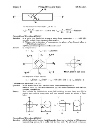
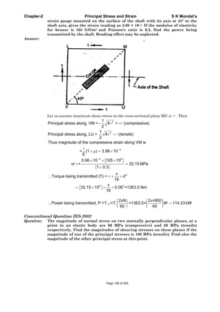
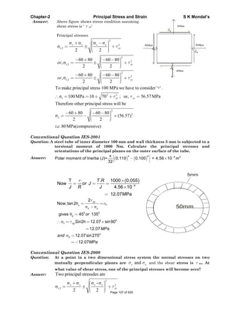
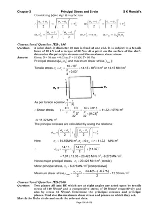
![Chapter-2 Principal Stress and Strain S K Mondal’s
Answer: Given
x
y
=140MPa(tensile)
=-70MPa(compressive)
35MPaxy
1 2Principal stresses; , ;
70N/mm
2
35Nmm
2
A
C B
140N/mm
2
x
2
2
1,2
2
2
1 2
We know that,
2 2
140 70 140 70
35 35 110.7
2 2
Therefore =145.7 MPa and 75.7MPa
x y y
xy
y
-
1 2
1 2
max
Position of Principal planes ,
2 2 35
tan2 0.3333
140 70
145 75.7
Maximum shear stress, 110.7
2 2
xy
p
x
MPa
Mohr cirle:
xOL= 140
70
35
Joining ST that cuts at 'N'
y
xy
MPa
OM MPa
SM LT MPa
1
2
SN=NT=radius of Mohr circle =110.7 MPa
OV= 145.7
75.7
MPa
OV MPa
T
V
L
2 =198.4p
S
U
M O 2
140=
Y
N
Conventional Question IES-2010
Q6. The data obtained from a rectangular strain gauge rosette attached to a
stressed steel member are
6 0 6
0 45= 220 10 , 120 100 , and
6
90 =220 10 . Given that the value of E =
5 2
2 10 N / mm and Poisson’s
Ratio 0.3 , calculate the values of principal stresses acting at the point and
their directions. [10 Marks]
Ans. A rectangular strain gauge rosette strain
0
6 6 6
0 9045
11 2
220 10 120 10 220 10
E = 2 10 N / m poisson ratio 0.3
Find out principal stress and their direction.
Let a o c 90 b 45e e and e
We know that principal strain are
2 2a b
12 a b b c
e e
e e e e
2
6 6
2 2
6 6
220 10 120 10 1
220 120 10 120 220 10
2 2
6 61
50 10 354.40 10
2 Page 109 of 429](https://image.slidesharecdn.com/strengthofmaterialsbyskmondal-130102103545-phpapp02-150924095946-lva1-app6891/85/Strengthofmaterialsbyskmondal-130102103545-phpapp02-109-320.jpg)
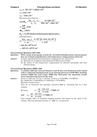
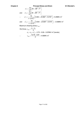
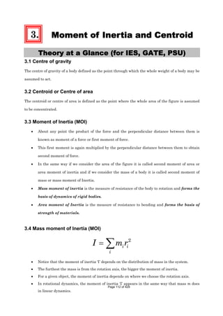
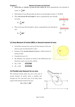
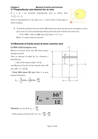
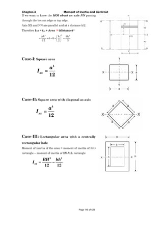
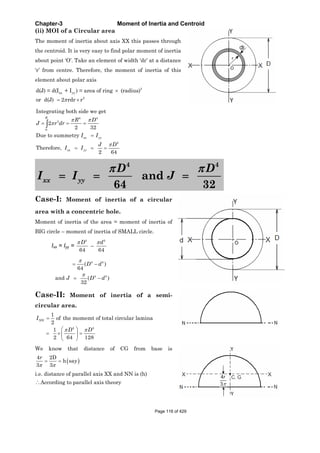
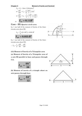
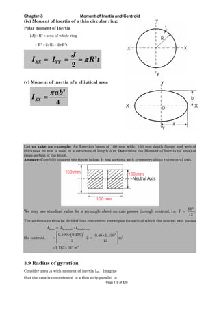
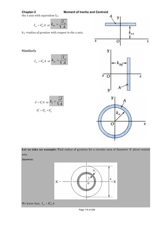
![Chapter-3 Moment of Inertia and Centroid
OBJECTIVE QUESTIONS (GATE, IES, IAS)
Previous 20-Years GATE Questions
Moment of Inertia (Second moment of an area)
GATE-1. The second moment of a circular area about the diameter is given by (D is the
diameter) [GATE-2003]
(a)
4
4
D
(b)
4
16
D
(c)
4
32
D
(d)
4
64
D
GATE-1. Ans. (d)
GATE-2. The area moment of inertia of a square of size 1 unit about its diagonal is:
[GATE-2001]
(a)
1
3
(b)
1
4
(c)
1
12
(d)
1
6
GATE-2. Ans. (c)
4
4
1
12 12
xx
a
I
Radius of Gyration
Data for Q3–Q4 are given below. Solve the problems and choose correct
answers.
A reel of mass “m” and radius of gyration “k” is rolling down smoothly from rest with one
end of the thread wound on it held in the ceiling as depicted in the figure. Consider the
thickness of the thread and its mass negligible in comparison with the radius “r” of the
hub and the reel mass “m”. Symbol “g” represents the acceleration due to gravity.
[GATE-2003]
Page 121 of 429](https://image.slidesharecdn.com/strengthofmaterialsbyskmondal-130102103545-phpapp02-150924095946-lva1-app6891/85/Strengthofmaterialsbyskmondal-130102103545-phpapp02-121-320.jpg)
![Chapter-3 Moment of Inertia and Centroid
GATE-3. The linear acceleration of the reel is:
(a)
2
2 2
gr
r k
(b)
2
2 2
gk
r k
(c) 2 2
grk
r k
(d)
2
2 2
mgr
r k
GATE-3. Ans. (a) For downward linear motion mg – T = mf, where f = linear tangential
acceleration = r , = rotational acceleration. Considering rotational motion
.Tr I
or, T = 2
2
f
mk
r
therefore mg – T = mf gives f =
2
2 2
gr
r k
GATE-4. The tension in the thread is:
(a)
2
2 2
mgr
r k
(b) 2 2
mgrk
r k
(c)
2
2 2
mgk
r k
(d) 2 2
mg
r k
GATE-4. Ans. (c)
2 2
2 2
2 2 2 2 2 2
f gr mgk
T mk mk
r r r k r k
Previous 20-Years IES Questions
Centroid
IES-1. Assertion (A): Inertia force always acts through the centroid of the body and is
directed opposite to the acceleration of the centroid. [IES-2001]
Reason (R): It has always a tendency to retard the motion.
(a) Both A and R are individually true and R is the correct explanation of A
(b) Both A and R are individually true but R is NOT the correct explanation of A
(c) A is true but R is false
(d) A is false but R is true
IES-1. Ans. (c) It has always a tendency to oppose the motion not retard. If we want to retard a
motion then it will wand to accelerate.
Page 122 of 429](https://image.slidesharecdn.com/strengthofmaterialsbyskmondal-130102103545-phpapp02-150924095946-lva1-app6891/85/Strengthofmaterialsbyskmondal-130102103545-phpapp02-122-320.jpg)
![Chapter-3 Moment of Inertia and Centroid
Radius of Gyration
IES-2. Figure shows a rigid body of mass
m having radius of gyration k
about its centre of gravity. It is to
be replaced by an equivalent
dynamical system of two masses
placed at A and B. The mass at A
should be:
(a)
a m
a b
(b)
b m
a b
(c)
3
m a
b
(d)
2
m b
a
[IES-2003]
IES-2. Ans. (b)
IES-3. Force required to accelerate a cylindrical body which rolls without slipping on a
horizontal plane (mass of cylindrical body is m, radius of the cylindrical
surface in contact with plane is r, radius of gyration of body is k and
acceleration of the body is a) is: [IES-2001]
(a) 2 2
/ 1 .m k r a (b) 2 2
/ .mk r a (c) 2
.mk a (d) 2
/ 1 .mk r a
IES-3. Ans. (a)
IES-4. A body of mass m and radius of gyration k is to be replaced by two masses m1 and
m2 located at distances h1 and h2 from the CG of the original body. An
equivalent dynamic system will result, if [IES-2001]
(a) 1 2h h k (b)
2 2 2
1 2h h k (c)
2
1 2h h k (d)
2
1 2h h k
IES-4. Ans. (c)
Previous 20-Years IAS Questions
Radius of Gyration
IAS-1. A wheel of centroidal radius of gyration 'k' is rolling on a horizontal surface
with constant velocity. It comes across an obstruction of height 'h' Because of
its rolling speed, it just overcomes the obstruction. To determine v, one should
use the principle (s) of conservation of [IAS 1994]
(a) Energy (b) Linear momentum
(c) Energy and linear momentum (d) Energy and angular momentum
IAS-1. Ans. (a)
Page 123 of 429](https://image.slidesharecdn.com/strengthofmaterialsbyskmondal-130102103545-phpapp02-150924095946-lva1-app6891/85/Strengthofmaterialsbyskmondal-130102103545-phpapp02-123-320.jpg)
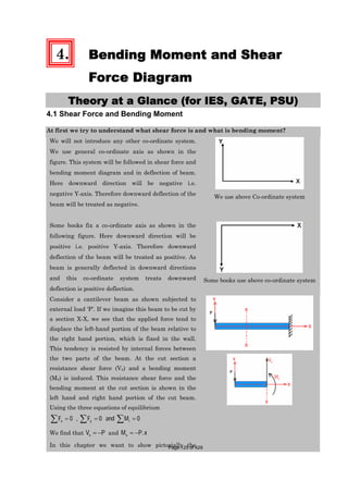
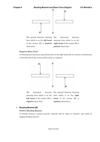
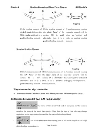
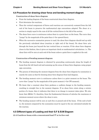
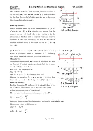
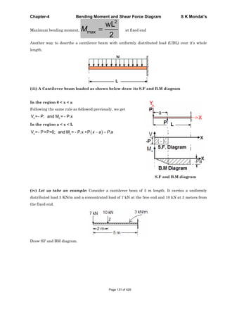
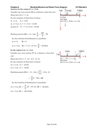
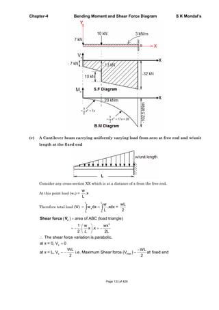
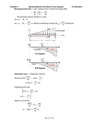
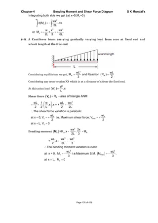
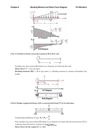
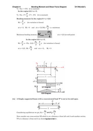
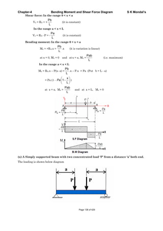
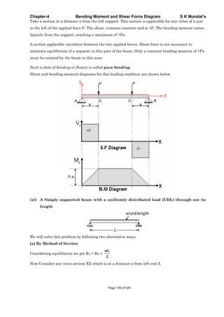
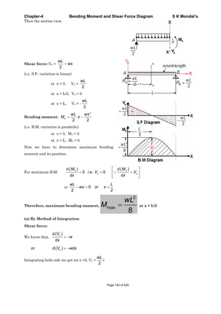
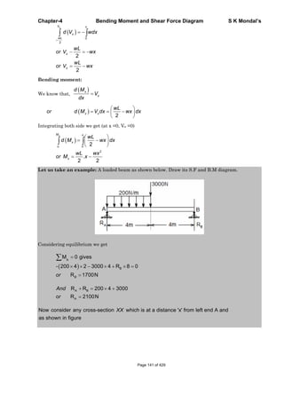
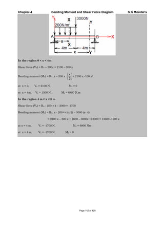
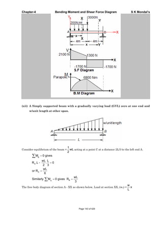
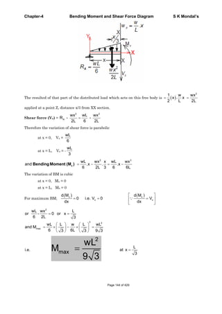
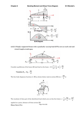
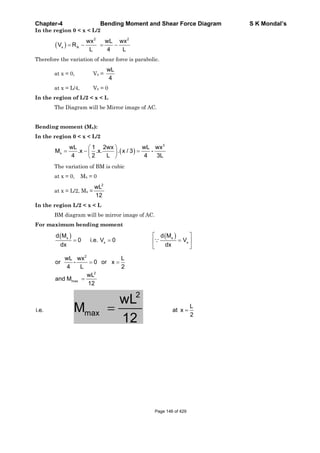
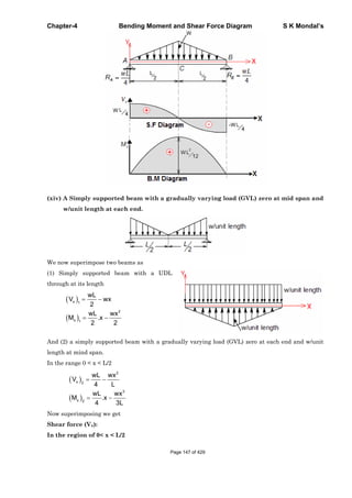
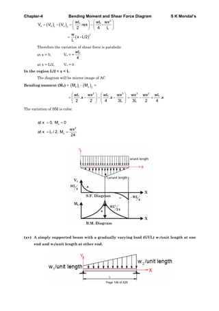
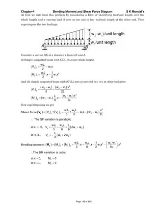
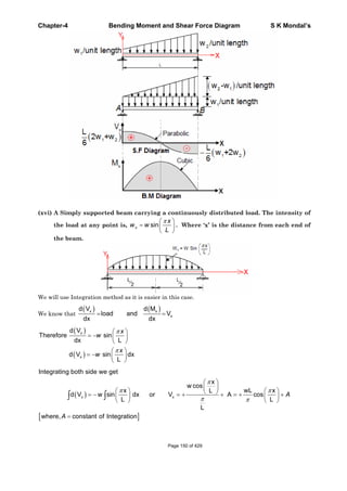
![Chapter-4 Bending Moment and Shear Force Diagram S K Mondal’s
x
x x x
2
x 2
Again we know that
d M wL x
V or d M V dx cos dx
dx L
Integrating both side we get
wL x
sin
wL xL
M x + B sin x + B
L
L
A
A A
[Where B = constant of Integration]
Now apply boundary conditions
At x = 0, Mx = 0 and at x = L, Mx = 0
This gives A = 0 and B = 0
x max
2
x 2
2
max 2
wL x wL
Shear force V cos and V at x 0
L
wL x
And M sin
L
wL
M at x = L/2
(xvii) A Simply supported beam with a couple or moment at a distance ‘a’ from left end.
Considering equilibrium we get
Page 151 of 429](https://image.slidesharecdn.com/strengthofmaterialsbyskmondal-130102103545-phpapp02-150924095946-lva1-app6891/85/Strengthofmaterialsbyskmondal-130102103545-phpapp02-151-320.jpg)
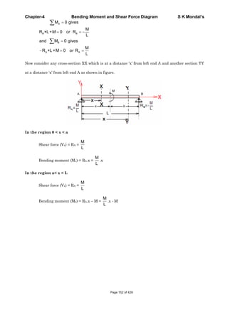
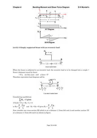
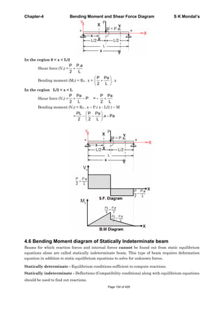
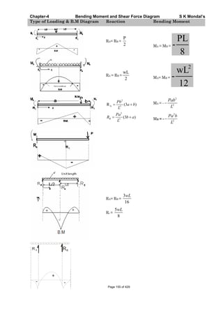
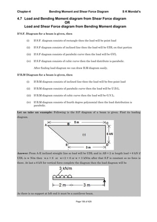
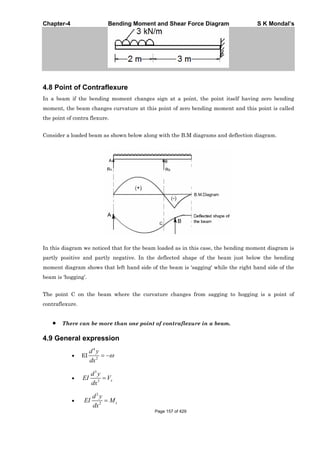
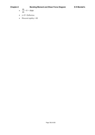
![Chapter-4 Bending Moment and Shear Force Diagram S K Mondal’s
OBJECTIVE QUESTIONS (GATE, IES, IAS)
Previous 20-Years GATE Questions
Shear Force (S.F.) and Bending Moment (B.M.)
GATE-1. A concentrated force, F is applied
(perpendicular to the plane of the figure) on
the tip of the bent bar shown in Figure. The
equivalent load at a section close to the fixed
end is:
(a) Force F
(b) Force F and bending moment FL
(c) Force F and twisting moment FL
(d) Force F bending moment F L, and twisting
moment FL
[GATE-1999]
GATE-1. Ans. (c)
GATE-2. The shear force in a beam subjected to pure positive bending is……
(positive/zero/negative) [GATE-1995]
GATE-2. Ans. Zero
Cantilever
GATE-3. Two identical cantilever beams are supported as shown, with their free ends in
contact through a rigid roller. After the load P is applied, the free ends will
have [GATE-2005]
(a) Equal deflections but not equal slopes
(b) Equal slopes but not equal deflections
(c) Equal slopes as well as equal deflections
(d) Neither equal slopes nor equal deflections
GATE-3. Ans. (a) As it is rigid roller, deflection must be same, because after deflection they also
will be in contact. But slope unequal.
GATE-4. A beam is made up of two
identical bars AB and BC, by
hinging them together at B. The
end A is built-in (cantilevered)
and the end C is simply-
supported. With the load P acting
as shown, the bending moment at
A is:
[GATE-2005]
Page 159 of 429](https://image.slidesharecdn.com/strengthofmaterialsbyskmondal-130102103545-phpapp02-150924095946-lva1-app6891/85/Strengthofmaterialsbyskmondal-130102103545-phpapp02-159-320.jpg)
![Chapter-4 Bending Moment and Shear Force Diagram S K Mondal’s
(a) Zero (b)
PL
2
(c)
3PL
2
(d) Indeterminate
GATE-4. Ans. (b)
Cantilever with Uniformly Distributed Load
GATE-5. The shapes of the bending moment diagram for a uniform cantilever beam
carrying a uniformly distributed load over its length is: [GATE-2001]
(a) A straight line (b) A hyperbola (c) An ellipse (d) A parabola
GATE-5. Ans. (d)
Cantilever Carrying load Whose Intensity varies
GATE-6. A cantilever beam carries the anti-
symmetric load shown, where o is
the peak intensity of the
distributed load. Qualitatively, the
correct bending moment diagram
for this beam is:
[GATE-2005]
GATE-6. Ans. (d)
Page 160 of 429](https://image.slidesharecdn.com/strengthofmaterialsbyskmondal-130102103545-phpapp02-150924095946-lva1-app6891/85/Strengthofmaterialsbyskmondal-130102103545-phpapp02-160-320.jpg)
![Chapter-4 Bending Moment and Shear Force Diagram S K Mondal’s
2 3
x
wx wx
M
2 6L
Simply Supported Beam Carrying Concentrated Load
GATE-7. A concentrated load of P acts on a simply supported beam of span L at a
distance
3
L
from the left support. The bending moment at the point of
application of the load is given by [GATE-2003]
2 2
( ) ( ) ( ) ( )
3 3 9 9
PL PL PL PL
a b c d
GATE-7. Ans. (d)
c
L 2L
P
Pab 2PL3 3
M
l L 9
GATE-8. A simply supported beam carries a load 'P'
through a bracket, as shown in Figure. The
maximum bending moment in the beam is
(a) PI/2 (b) PI/2 + aP/2
(c) PI/2 + aP (d) PI/2 – aP
[GATE-2000]
GATE-8. Ans. (c)
Taking moment about Ra
b
lP Pa R l 0
2
b a
P a P a
or R P R P
2 l 2 l
Maximum bending moment will be at centre ‘C’
c a b max
l l Pl
M R P a R or M Pa
2 2 2
Simply Supported Beam Carrying a Uniformly
Distributed Load
Statement for Linked Answer and Questions Q9-Q10:
A mass less beam has a loading pattern as shown in the figure. The beam is of rectangular
cross-section with a width of 30 mm and height of 100 mm. [GATE-2010]
Page 161 of 429](https://image.slidesharecdn.com/strengthofmaterialsbyskmondal-130102103545-phpapp02-150924095946-lva1-app6891/85/Strengthofmaterialsbyskmondal-130102103545-phpapp02-161-320.jpg)
![Chapter-4 Bending Moment and Shear Force Diagram S K Mondal’s
GATE-9. The maximum bending moment occurs at
(a) Location B (b) 2675 mm to the right of A
(c) 2500 mm to the right of A (d) 3225 mm to the right of A
GATE-9. Ans. (C)
R1 R2
3000 N/m
1 2
1
1
n
1
R R 3000 2 6000N
R 4 3000 2 1 0
R 1500,
S.F. eq . at any section x from end A.
R 3000 x 2 0 for x 2m}
x 2.5 m.
GATE-10. The maximum magnitude of bending stress (in MPa) is given by
(a) 60.0 (b) 67.5 (c) 200.0 (d) 225.0
GATE-10. Ans. (b)
Binding stress will be maximum at the outer surface
So taking 9 = 50 mm
3
3
2
3
x
6
2500
6
3
50
and &
12
12
m 1.5 10 [2000 ]
2
3.375 10
3.375 10 50 12
67.5
30 100
ld m
I
dl
x
x
m N mm
MPa
Data for Q11-Q12 are given below. Solve the problems and choose correct
answers
A steel beam of breadth 120 mm and
height 750 mm is loaded as shown in the
figure. Assume Esteel= 200 GPa.
[GATE-2004]
GATE-11. The beam is subjected to a maximum bending moment of
(a) 3375 kNm (b) 4750 kNm (c) 6750 kNm (d) 8750 kNmPage 162 of 429](https://image.slidesharecdn.com/strengthofmaterialsbyskmondal-130102103545-phpapp02-150924095946-lva1-app6891/85/Strengthofmaterialsbyskmondal-130102103545-phpapp02-162-320.jpg)
![Chapter-4 Bending Moment and Shear Force Diagram S K Mondal’s
GATE-11. Ans. (a)
2 2
max
wl 120 15
M kNm 3375kNm
8 8
GATE-12. The value of maximum deflection of the beam is:
(a) 93.75 mm (b) 83.75 mm (c) 73.75 mm (d) 63.75 mm
GATE-12. Ans. (a) Moment of inertia (I) =
33
3 4
0.12 0.75bh
4.22 10 m
12 12
4 3 4
max 9 3
5 wl 5 120 10 15
m 93.75mm
384 EI 384 200 10 4.22 10
Statement for Linked Answer and Questions Q13-Q14:
A simply supported beam of span length 6m and 75mm diameter carries a uniformly
distributed load of 1.5 kN/m [GATE-2006]
GATE-13. What is the maximum value of bending moment?
(a) 9 kNm (b) 13.5 kNm (c) 81 kNm (d) 125 kNm
GATE-13. Ans. (a)
2 2
max
wl 1.5 6
M 6.75kNm
8 8
But not in choice. Nearest choice (a)
GATE-14. What is the maximum value of bending stress?
(a) 162.98 MPa (b) 325.95 MPa (c) 625.95 Mpa (d) 651.90 Mpa
GATE-14. Ans. (a)
3
3 2
32M 32 6.75 10
Pa 162.98MPa
d 0.075
Simply Supported Beam Carrying a Load whose
Intensity varies Uniformly from Zero at each End to w
per Unit Run at the MiD Span
GATE-15. A simply supported beam is
subjected to a distributed
loading as shown in the
diagram given below:
What is the maximum shear
force in the beam?
(a) WL/3 (b) WL/2
(c) WL/3 (d) WL/6
[IES-2004]
GATE-15. Ans. (d)
2
x
max at x 0
1 WL
Total load L W
2 2
WL 1 W WL Wx
S x. X
L4 2 4 L
2
WL
S
4
GATE-16. A simply supported beam of length 'l' is subjected to a symmetrical uniformly
varying load with zero intensity at the ends and intensity w (load per unit
length) at the mid span. What is the maximum bending moment? [IAS-2004]
Page 163 of 429](https://image.slidesharecdn.com/strengthofmaterialsbyskmondal-130102103545-phpapp02-150924095946-lva1-app6891/85/Strengthofmaterialsbyskmondal-130102103545-phpapp02-163-320.jpg)
![Chapter-4 Bending Moment and Shear Force Diagram S K Mondal’s
(a)
2
3
8
wl
(b)
2
12
wl
(c)
2
24
wl
(d)
2
5
12
wl
GATE-16. Ans. (b)
Previous 20-Years IES Questions
Shear Force (S.F.) and Bending Moment (B.M.)
IES-1. A lever is supported on two
hinges at A and C. It carries a
force of 3 kN as shown in the
above figure. The bending
moment at B will be
(a) 3 kN-m (b) 2 kN-m
(c) 1 kN-m (d) Zero
[IES-1998]
IES-1. Ans. (a)
IES-2. A beam subjected to a load P is shown in
the given figure. The bending moment at
the support AA of the beam will be
(a) PL (b) PL/2
(c) 2PL (d) zero
[IES-1997]
IES-2. Ans. (b) Load P at end produces moment
2
PL
in
anticlockwise direction. Load P at end
produces moment of PL in clockwise
direction. Net moment at AA is PL/2.
IES-3. The bending moment (M) is constant over a length segment (I) of a beam. The
shearing force will also be constant over this length and is given by [IES-1996]
(a) M/l (b) M/2l (c) M/4l (d) None of the above
IES-3. Ans. (d) Dimensional analysis gives choice (d)
IES-4. A rectangular section beam subjected to a bending moment M varying along its
length is required to develop same maximum bending stress at any cross-
section. If the depth of the section is constant, then its width will vary as
[IES-1995]
(a) M (b) M (c) M2 (d) 1/M
IES-4. Ans. (a)
3
M bh
const. and I
I 12
IES-5. Consider the following statements: [IES-1995]
If at a section distant from one of the ends of the beam, M represents the
bending moment. V the shear force and w the intensity of loading, then
1. dM/dx = V 2. dV/dx = w
3. dw/dx = y (the deflection of the beam at the section)
Select the correct answer using the codes given below:
(a) 1 and 3 (b) 1 and 2 (c) 2 and 3 (d) 1, 2 and 3
IES-5. Ans. (b) Page 164 of 429](https://image.slidesharecdn.com/strengthofmaterialsbyskmondal-130102103545-phpapp02-150924095946-lva1-app6891/85/Strengthofmaterialsbyskmondal-130102103545-phpapp02-164-320.jpg)
![Chapter-4 Bending Moment and Shear Force Diagram S K Mondal’s
Cantilever
IES-6. The given figure shows a beam BC simply supported at C and hinged at B (free
end) of a cantilever AB. The beam and the cantilever carry forces of
100 kg and 200 kg respectively. The bending moment at B is: [IES-1995]
(a) Zero (b) 100 kg-m (c) 150 kg-m (d) 200 kg-m
IES-6. Ans. (a)
IES-7. Match List-I with List-II and select the correct answer using the codes given
below the lists: [IES-1993]
List-I List-II
(Condition of beam) (Bending moment diagram)
A. Subjected to bending moment at the 1. Triangle
end of a cantilever
B. Cantilever carrying uniformly distributed 2. Cubic parabola
load over the whole length
C. Cantilever carrying linearly varying load 3. Parabola
from zero at the fixed end to maximum at
the support
D. A beam having load at the centre and 4. Rectangle
supported at the ends
Codes: A B C D A B C D
(a) 4 1 2 3 (b) 4 3 2 1
(c) 3 4 2 1 (d) 3 4 1 2
IES-7. Ans. (b)
IES-8. If the shear force acting at every section of a beam is of the same magnitude
and of the same direction then it represents a [IES-1996]
(a) Simply supported beam with a concentrated load at the centre.
(b) Overhung beam having equal overhang at both supports and carrying equal
concentrated loads acting in the same direction at the free ends.
(c) Cantilever subjected to concentrated load at the free end.
(d) Simply supported beam having concentrated loads of equal magnitude and in the
same direction acting at equal distances from the supports.
IES-8. Ans. (c)
Cantilever with Uniformly Distributed Load
IES-9. A uniformly distributed load (in kN/m) is acting over the entire length of a 3
m long cantilever beam. If the shear force at the midpoint of cantilever is 6 kN,
what is the value of ? [IES-2009]
(a) 2 (b) 3 (c) 4 (d) 5
IES-9. Ans. (c)
Shear force at mid point of cantilever
6
2
3
6
2
6 2
4 kN / m
3
l
Page 165 of 429](https://image.slidesharecdn.com/strengthofmaterialsbyskmondal-130102103545-phpapp02-150924095946-lva1-app6891/85/Strengthofmaterialsbyskmondal-130102103545-phpapp02-165-320.jpg)
![Chapter-4 Bending Moment and Shear Force Diagram S K Mondal’s
IES-10. Match List-I with List-II and select the correct answer using the code given
below the Lists: [IES-2009]
Code: A B C D A B C D
(a) 1 5 2 4 (b) 4 5 2 3
(c) 1 3 4 5 (d) 4 2 5 3
IES-10. Ans. (b)
IES-11. The shearing force diagram for a
beam is shown in the above figure.
The bending moment diagram is
represented by which one of the
following?
[IES-2008]
IES-11. Ans. (b) Uniformly distributed load on cantilever beam.
Page 166 of 429](https://image.slidesharecdn.com/strengthofmaterialsbyskmondal-130102103545-phpapp02-150924095946-lva1-app6891/85/Strengthofmaterialsbyskmondal-130102103545-phpapp02-166-320.jpg)
![Chapter-4 Bending Moment and Shear Force Diagram S K Mondal’s
IES-12. A cantilever beam having 5 m length is so loaded that it develops a shearing
force of 20T and a bending moment of 20 T-m at a section 2m from the free end.
Maximum shearing force and maximum bending moment developed in the
beam under this load are respectively 50 T and 125 T-m. The load on the beam
is: [IES-1995]
(a) 25 T concentrated load at free end
(b) 20T concentrated load at free end
(c) 5T concentrated load at free end and 2 T/m load over entire length
(d) 10 T/m udl over entire length
IES-12. Ans. (d)
Cantilever Carrying Uniformly Distributed Load for a
Part of its Length
IES-13. A vertical hanging bar of length L and weighing w N/ unit length carries a load
W at the bottom. The tensile force in the bar at a distance Y from the support
will be given by [IES-1992]
a b ( ) c / d ( )
W
W wL W w L y W w y L W L y
w
IES-13. Ans. (b)
Cantilever Carrying load Whose Intensity varies
IES-14. A cantilever beam of 2m length supports a triangularly distributed load over
its entire length, the maximum of which is at the free end. The total load is 37.5
kN.What is the bending moment at the fixed end? [IES 2007]
(a) 50 106 N mm (b) 12.5 106 N mm (c) 100 106 N mm (d) 25 106 N mm
IES-14. Ans. (a)
Page 167 of 429](https://image.slidesharecdn.com/strengthofmaterialsbyskmondal-130102103545-phpapp02-150924095946-lva1-app6891/85/Strengthofmaterialsbyskmondal-130102103545-phpapp02-167-320.jpg)
![Chapter-4 Bending Moment and Shear Force Diagram S K Mondal’s
M = 37.5
3
4
KNm = 50 106 Nmm
Simply Supported Beam Carrying Concentrated Load
IES-15. Assertion (A): If the bending moment along the length of a beam is constant,
then the beam cross section will not experience any shear stress. [IES-1998]
Reason (R): The shear force acting on the beam will be zero everywhere along
the length.
(a) Both A and R are individually true and R is the correct explanation of A
(b) Both A and R are individually true but R is NOT the correct explanation of A
(c) A is true but R is false
(d) A is false but R is true
IES-15. Ans. (a)
IES-16. Assertion (A): If the bending moment diagram is a rectangle, it indicates that
the beam is loaded by a uniformly distributed moment all along the length.
Reason (R): The BMD is a representation of internal forces in the beam and not
the moment applied on the beam. [IES-2002]
(a) Both A and R are individually true and R is the correct explanation of A
(b) Both A and R are individually true but R is NOT the correct explanation of A
(c) A is true but R is false
(d) A is false but R is true
IES-16. Ans. (d)
IES-17. The maximum bending moment in a simply supported beam of length L loaded
by a concentrated load W at the midpoint is given by [IES-1996]
(a) WL (b)
2
WL
(c)
4
WL
(d)
8
WL
IES-17. Ans. (c)
IES-18. A simply supported beam is
loaded as shown in the above
figure. The maximum shear force
in the beam will be
(a) Zero (b) W
(c) 2W (d) 4W
[IES-1998]
IES-18. Ans. (c)
IES-19. If a beam is subjected to a constant bending moment along its length, then the
shear force will [IES-1997]
(a) Also have a constant value everywhere along its length
(b) Be zero at all sections along the beam
(c) Be maximum at the centre and zero at the ends (d) zero at the centre and
maximum at the ends
IES-19. Ans. (b)
Page 168 of 429](https://image.slidesharecdn.com/strengthofmaterialsbyskmondal-130102103545-phpapp02-150924095946-lva1-app6891/85/Strengthofmaterialsbyskmondal-130102103545-phpapp02-168-320.jpg)
![Chapter-4 Bending Moment and Shear Force Diagram S K Mondal’s
IES-20. A loaded beam is shown in
the figure. The bending
moment diagram of the
beam is best represented as:
[IES-2000]
IES-20. Ans. (a)
IES-21. A simply supported beam has equal over-hanging lengths and carries equal
concentrated loads P at ends. Bending moment over the length between the
supports [IES-2003]
(a) Is zero (b) Is a non-zero constant
(c) Varies uniformly from one support to the other (d) Is maximum at mid-span
IES-21. Ans. (b)
IES-22. The bending moment diagram for the case shown below will be q as shown in
(a) (b)
(c) (d)
[IES-1992]
IES-22. Ans. (a)
Page 169 of 429](https://image.slidesharecdn.com/strengthofmaterialsbyskmondal-130102103545-phpapp02-150924095946-lva1-app6891/85/Strengthofmaterialsbyskmondal-130102103545-phpapp02-169-320.jpg)
![Chapter-4 Bending Moment and Shear Force Diagram S K Mondal’s
IES-23. Which one of the following
portions of the loaded beam
shown in the given figure is
subjected to pure bending?
(a) AB (b)DE
(c) AE (d) BD
[IES-1999]
IES-23. Ans. (d) Pure bending takes place in the section between two weights W
IES-24. Constant bending moment over span "l" will occur in [IES-1995]
IES-24. Ans. (d)
IES-25. For the beam shown in the above
figure, the elastic curve between the
supports B and C will be:
(a) Circular (b) Parabolic
(c) Elliptic (d) A straight line
[IES-1998]
IES-25. Ans. (b)
IES-26. A beam is simply supported at its ends and is loaded by a couple at its mid-span
as shown in figure A. Shear force diagram for the beam is given by the figure.
[IES-1994]
(a) B (b) C (c) D (d) E
IES-26. Ans. (d)
IES-27. A beam AB is hinged-supported at its ends and is loaded by couple P.c. as
shown in the given figure. The magnitude or shearing force at a section x of the
beam is: [IES-1993]
(a) 0 (b) P (c) P/2L (d) P.c./2L
Page 170 of 429](https://image.slidesharecdn.com/strengthofmaterialsbyskmondal-130102103545-phpapp02-150924095946-lva1-app6891/85/Strengthofmaterialsbyskmondal-130102103545-phpapp02-170-320.jpg)
![Chapter-4 Bending Moment and Shear Force Diagram S K Mondal’s
IES-27. Ans. (d) If F be the shearing force at section x (at point A), then taking moments about B, F
x 2L = Pc
Thus shearing force in zone x
2 2
Pc Pc
or F
L L
Simply Supported Beam Carrying a Uniformly
Distributed Load
IES-28. A freely supported beam at its ends carries a central concentrated load, and maximum
bending moment is M. If the same load be uniformly distributed over the beam length,
then what is the maximum bending moment? [IES-2009]
(a) M (b)
2
M
(c)
3
M
(d) 2M
IES-28. Ans. (b)
Max
WL
B.M M
4
Where the Load is U.D.L.
Maximum Bending Moment
2
W L
L 8
WL 1 WL M
8 2 4 2
Page 171 of 429](https://image.slidesharecdn.com/strengthofmaterialsbyskmondal-130102103545-phpapp02-150924095946-lva1-app6891/85/Strengthofmaterialsbyskmondal-130102103545-phpapp02-171-320.jpg)
![Chapter-4 Bending Moment and Shear Force Diagram S K Mondal’s
Simply Supported Beam Carrying a Load whose
Intensity varies Uniformly from Zero at each End to w
per Unit Run at the MiD Span
IES-29. A simply supported beam is
subjected to a distributed
loading as shown in the
diagram given below:
What is the maximum shear
force in the beam?
(a) WL/3 (b) WL/2
(c) WL/3 (d) WL/6
[IES-2004]
IES-29. Ans. (d)
2
x
max at x 0
1 WL
Total load L W
2 2
WL 1 W WL Wx
S x. X
L4 2 4 L
2
WL
S
4
Simply Supported Beam carrying a Load whose
Intensity varies
IES-30. A beam having uniform cross-section carries a uniformly distributed load of
intensity q per unit length over its entire span, and its mid-span deflection is .
The value of mid-span deflection of the same beam when the same load is
distributed with intensity varying from 2q unit length at one end to zero at the
other end is: [IES-1995]
(a) 1/3 (b) 1/2 (c) 2/3 (d)
IES-30. Ans. (d)
Simply Supported Beam with Equal Overhangs and
carrying a Uniformly Distributed Load
IES-31. A beam, built-in at both ends, carries a uniformly distributed load over its
entire span as shown in figure-I. Which one of the diagrams given below,
represents bending moment distribution along the length of the beam?
[IES-1996]
Page 172 of 429](https://image.slidesharecdn.com/strengthofmaterialsbyskmondal-130102103545-phpapp02-150924095946-lva1-app6891/85/Strengthofmaterialsbyskmondal-130102103545-phpapp02-172-320.jpg)
![Chapter-4 Bending Moment and Shear Force Diagram S K Mondal’s
IES-31. Ans. (d)
The Points of Contraflexure
IES-32. The point· of contraflexure is a point where: [IES-2005]
(a) Shear force changes sign (b) Bending moment changes sign
(c) Shear force is maximum (d) Bending moment is maximum
IES-32. Ans. (b)
IES-33. Match List I with List II and select the correct answer using the codes given
below the Lists: [IES-2000]
List-I List-II
A. Bending moment is constant 1. Point of contraflexure
B. Bending moment is maximum or minimum 2. Shear force changes sign
C. Bending moment is zero 3. Slope of shear force diagram is
zero over the portion of the beam
D. Loading is constant 4. Shear force is zero over the
portion of the beam
Code: A B C D A B C D
(a) 4 1 2 3 (b) 3 2 1 4
(c) 4 2 1 3 (d) 3 1 2 4
IES-33. Ans. (b)
Loading and B.M. diagram from S.F. Diagram
IES-34. The bending moment diagram shown in Fig. I correspond to the shear force
diagram in [IES-1999]
IES-34. Ans. (b) If shear force is zero, B.M. will also be zero. If shear force varies linearly with
length, B.M. diagram will be curved line.
IES-35. Bending moment distribution in a built be am is shown in the given
Page 173 of 429](https://image.slidesharecdn.com/strengthofmaterialsbyskmondal-130102103545-phpapp02-150924095946-lva1-app6891/85/Strengthofmaterialsbyskmondal-130102103545-phpapp02-173-320.jpg)
![Chapter-4 Bending Moment and Shear Force Diagram S K Mondal’s
The shear force distribution in the beam is represented by [IES-2001]
IES-35. Ans. (a)
IES-36. The given figure shows the
shear force diagram for the
beam ABCD.
Bending moment in the portion
BC of the beam
[IES-1996]
(a) Is a non-zero constant (b) Is zero
(c) Varies linearly from B to C (d) Varies parabolically from B to C
IES-36. Ans. (a)
IES-37. Figure shown above represents the
BM diagram for a simply supported
beam. The beam is subjected to
which one of the following?
(a) A concentrated load at its mid-
length
(b) A uniformly distributed load over
its length
(c) A couple at its mid-length
(d) Couple at 1/4 of the span from each
end
[IES-2006]
IES-37. Ans. (c)
IES-38. If the bending moment diagram for
a simply supported beam is of the
form given below.
Then the load acting on the beam
is:
(a) A concentrated force at C
(b) A uniformly distributed load over
the whole length of the beam
(c) Equal and opposite moments
applied at A and B
(d) A moment applied at C [IES-1994]
IES-38. Ans. (d) A vertical line in centre of B.M. diagram is possible when a moment is applied
there.
IES-39. The figure given below shows a bending moment diagram for the beam CABD:
Page 174 of 429](https://image.slidesharecdn.com/strengthofmaterialsbyskmondal-130102103545-phpapp02-150924095946-lva1-app6891/85/Strengthofmaterialsbyskmondal-130102103545-phpapp02-174-320.jpg)
![Chapter-4 Bending Moment and Shear Force Diagram S K Mondal’s
Load diagram for the above beam will be: [IES-1993]
IES-39. Ans. (a) Load diagram at (a) is correct because B.M. diagram between A and B is parabola
which is possible with uniformly distributed load in this region.
IES-40. The shear force diagram shown in the following figure is that of a [IES-1994]
(a) Freely supported beam with symmetrical point load about mid-span.
(b) Freely supported beam with symmetrical uniformly distributed load about mid-
span
(c) Simply supported beam with positive and negative point loads symmetrical about
the mid-span
(d) Simply supported beam with symmetrical varying load about mid-span
IES-40. Ans. (b) The shear force diagram is possible on simply supported beam with symmetrical
varying load about mid span.
Previous 20-Years IAS Questions
Shear Force (S.F.) and Bending Moment (B.M.)
IAS-1. Assertion (A): A beam subjected only to end moments will be free from shearing
force. [IAS-2004]
Reason (R): The bending moment variation along the beam length is zero.
(a) Both A and R are individually true and R is the correct explanation of A
Page 175 of 429](https://image.slidesharecdn.com/strengthofmaterialsbyskmondal-130102103545-phpapp02-150924095946-lva1-app6891/85/Strengthofmaterialsbyskmondal-130102103545-phpapp02-175-320.jpg)
![Chapter-4 Bending Moment and Shear Force Diagram S K Mondal’s
(b) Both A and R are individually true but R is NOT the correct explanation of A
(c) A is true but R is false
(d) A is false but R is true
IAS-1. Ans. (a)
IAS-2. Assertion (A): The change in bending moment between two cross-sections of a
beam is equal to the area of the shearing force diagram between the two
sections. [IAS-1998]
Reason (R): The change in the shearing force between two cross-sections of
beam due to distributed loading is equal to the area of the load intensity
diagram between the two sections.
(a) Both A and R are individually true and R is the correct explanation of A
(b) Both A and R are individually true but R is NOT the correct explanation of A
(c) A is true but R is false
(d) A is false but R is true
IAS-2. Ans. (b)
IAS-3. The ratio of the area under the bending moment diagram to the flexural
rigidity between any two points along a beam gives the change in [IAS-1998]
(a) Deflection (b) Slope (c) Shear force (d) Bending moment
IAS-3. Ans. (b)
Cantilever
IAS-4. A beam AB of length 2 L having a
concentrated load P at its mid-span
is hinge supported at its two ends A
and B on two identical cantilevers as
shown in the given figure. The
correct value of bending moment at
A is
(a) Zero (b) PLl2
(c) PL (d) 2 PL [IAS-1995]
IAS-4. Ans. (a) Because of hinge support between beam AB and cantilevers, the bending moment
can't be transmitted to cantilever. Thus bending moment at points A and B is zero.
IAS-5. A load perpendicular to the plane of the handle is applied at the free end as
shown in the given figure. The values of Shear Forces (S.F.), Bending Moment
(B.M.) and torque at the fixed end of the handle have been determined
respectively as 400 N, 340 Nm and 100 by a student. Among these values, those
of [IAS-1999]
(a) S.F., B.M. and torque are correct
(b) S.F. and B.M. are correct
(c) B.M. and torque are correct
(d) S.F. and torque are correct
IAS-5. Ans. (d)
S.F 400N and BM 400 0.4 0.2 240Nm
Torque 400 0.25 100Nm
Cantilever with Uniformly Distributed Load
IAS-6. If the SF diagram for a beam is a triangle with length of the beam as its base,
the beam is: [IAS-2007]
(a) A cantilever with a concentrated load at its free end
(b) A cantilever with udl over its whole span
(c) Simply supported with a concentrated load at its mid-point
(d) Simply supported with a udl over its whole span
Page 176 of 429](https://image.slidesharecdn.com/strengthofmaterialsbyskmondal-130102103545-phpapp02-150924095946-lva1-app6891/85/Strengthofmaterialsbyskmondal-130102103545-phpapp02-176-320.jpg)
![Chapter-4 Bending Moment and Shear Force Diagram S K Mondal’s
IAS-6. Ans. (b)
IAS-7. A cantilever carrying a uniformly distributed load is shown in Fig. I.
Select the correct R.M. diagram of the cantilever. [IAS-1999]
IAS-7. Ans. (c)
2
x
x wx
M wx
2 2
IAS-8. A structural member ABCD is loaded
as shown in the given figure. The
shearing force at any section on the
length BC of the member is:
(a) Zero (b) P
(c) Pa/k (d) Pk/a
[IAS-1996]
IAS-8. Ans. (a)
Cantilever Carrying load Whose Intensity varies
IAS-9. The beam is loaded as shown in Fig. I. Select the correct B.M. diagram
[IAS-1999]
Page 177 of 429](https://image.slidesharecdn.com/strengthofmaterialsbyskmondal-130102103545-phpapp02-150924095946-lva1-app6891/85/Strengthofmaterialsbyskmondal-130102103545-phpapp02-177-320.jpg)
![Chapter-4 Bending Moment and Shear Force Diagram S K Mondal’s
IAS-9. Ans. (d)
Simply Supported Beam Carrying Concentrated Load
IAS-10. Assertion (A): In a simply supported beam carrying a concentrated load at mid-
span, both the shear force and bending moment diagrams are triangular in
nature without any change in sign. [IAS-1999]
Reason (R): When the shear force at any section of a beam is either zero or
changes sign, the bending moment at that section is maximum.
(a) Both A and R are individually true and R is the correct explanation of A
(b) Both A and R are individually true but R is NOT the correct explanation of A
(c) A is true but R is false
(d) A is false but R is true
IAS-10. Ans. (d) A is false.
IAS-11. For the shear force to be uniform throughout the span of a simply supported
beam, it should carry which one of the following loadings? [IAS-2007]
(a) A concentrated load at mid-span
(b) Udl over the entire span
(c) A couple anywhere within its span
(d) Two concentrated loads equal in magnitude and placed at equal distance from each
support
Page 178 of 429](https://image.slidesharecdn.com/strengthofmaterialsbyskmondal-130102103545-phpapp02-150924095946-lva1-app6891/85/Strengthofmaterialsbyskmondal-130102103545-phpapp02-178-320.jpg)
![Chapter-4 Bending Moment and Shear Force Diagram S K Mondal’s
IAS-11. Ans. (d) It is a case of pure bending.
IAS-12. Which one of the following figures represents the correct shear force diagram
for the loaded beam shown in the given figure I? [IAS-1998; IAS-1995]
IAS-12. Ans. (a)
Simply Supported Beam Carrying a Uniformly
Distributed Load
IAS-13. For a simply supported beam of length fl' subjected to downward load of
uniform intensity w, match List-I with List-II and select the correct answer
using the codes given below the Lists: [IAS-1997]
List-I List-II
A. Slope of shear force diagram 1.
4
5
384
w
E I
B. Maximum shear force 2. w
C. Maximum deflection 3.
4
8
w
D. Magnitude of maximum bending moment 4.
2
w
Codes: A B C D A B C D
(a) 1 2 3 4 (b) 3 1 2 4
(c) 3 2 1 4 (d) 2 4 1 3Page 179 of 429](https://image.slidesharecdn.com/strengthofmaterialsbyskmondal-130102103545-phpapp02-150924095946-lva1-app6891/85/Strengthofmaterialsbyskmondal-130102103545-phpapp02-179-320.jpg)
![Chapter-4 Bending Moment and Shear Force Diagram S K Mondal’s
IAS-13. Ans. (d)
Simply Supported Beam Carrying a Load whose
Intensity varies Uniformly from Zero at each End to w
per Unit Run at the MiD Span
IAS-14. A simply supported beam of length 'l' is subjected to a symmetrical uniformly
varying load with zero intensity at the ends and intensity w (load per unit
length) at the mid span. What is the maximum bending moment? [IAS-2004]
(a)
2
3
8
wl
(b)
2
12
wl
(c)
2
24
wl
(d)
2
5
12
wl
IAS-14. Ans. (b)
Simply Supported Beam carrying a Load whose
Intensity varies
IAS-15. A simply supported beam of span l is subjected to a uniformly varying load
having zero intensity at the left support and w N/m at the right support. The
reaction at the right support is: [IAS-2003]
(a)
2
wl
(b)
5
wl
(c)
4
wl
(d)
3
wl
IAS-15. Ans. (d)
Simply Supported Beam with Equal Overhangs and
carrying a Uniformly Distributed Load
IAS-16. Consider the following statements for a simply supported beam subjected to a
couple at its mid-span: [IAS-2004]
1. Bending moment is zero at the ends and maximum at the centre
2. Bending moment is constant over the entire length of the beam
3. Shear force is constant over the entire length of the beam
4. Shear force is zero over the entire length of the beam
Which of the statements given above are correct?
(a) 1, 3 and 4 (b) 2, 3 and 4 (c) 1 and 3 (d) 2 and 4
IAS-16. Ans. (c)
Page 180 of 429](https://image.slidesharecdn.com/strengthofmaterialsbyskmondal-130102103545-phpapp02-150924095946-lva1-app6891/85/Strengthofmaterialsbyskmondal-130102103545-phpapp02-180-320.jpg)
![Chapter-4 Bending Moment and Shear Force Diagram S K Mondal’s
IAS-17. Match List-I (Beams) with List-II (Shear force diagrams) and select the correct
answer using the codes given below the Lists: [IAS-2001]
Codes: A B C D A B C D
(a) 4 2 5 3 (b) 1 4 5 3
(c) 1 4 3 5 (d) 4 2 3 5
IAS-17. Ans. (d)
The Points of Contraflexure
IAS-18. A point, along the length of a beam subjected to loads, where bending moment
changes its sign, is known as the point of [IAS-1996]
(a) Inflexion (b) Maximum stress (c) Zero shear force (d) Contra flexure
IAS-18. Ans. (d)
IAS-19. Assertion (A): In a loaded beam, if the shear force diagram is a straight line
parallel to the beam axis, then the bending moment is a straight line inclined
to the beam axis. [IAS 1994]
Reason (R): When shear force at any section of a beam is zero or changes sign,
the bending moment at that section is maximum.
(a) Both A and R are individually true and R is the correct explanation of A
(b) Both A and R are individually true but R is NOT the correct explanation of A
Page 181 of 429](https://image.slidesharecdn.com/strengthofmaterialsbyskmondal-130102103545-phpapp02-150924095946-lva1-app6891/85/Strengthofmaterialsbyskmondal-130102103545-phpapp02-181-320.jpg)
![Chapter-4 Bending Moment and Shear Force Diagram S K Mondal’s
(c) A is true but R is false
(d) A is false but R is true
IAS-19. Ans. (b)
Loading and B.M. diagram from S.F. Diagram
IAS-20. The shear force diagram of a
loaded beam is shown in the
following figure:
The maximum Bending Moment of
the beam is:
(a) 16 kN-m (b) 11 kN-m
(c) 28 kN-m (d) 8 kN-m
[IAS-1997]
IAS-20. Ans. (a)
IAS-21. The bending moment for a loaded beam is shown below: [IAS-2003]
The loading on the beam is represented by which one of the followings
diagrams?
(a) (b)
(c) (d)
IAS-21. Ans. (d)
Page 182 of 429](https://image.slidesharecdn.com/strengthofmaterialsbyskmondal-130102103545-phpapp02-150924095946-lva1-app6891/85/Strengthofmaterialsbyskmondal-130102103545-phpapp02-182-320.jpg)
![Chapter-4 Bending Moment and Shear Force Diagram S K Mondal’s
IAS-22. Which one of the given bending moment diagrams correctly represents that of
the loaded beam shown in figure? [IAS-1997]
IAS-22. Ans. (c) Bending moment does not depends on moment of inertia.
IAS-23. The shear force diagram is shown
above for a loaded beam. The
corresponding bending moment
diagram is represented by
[IAS-2003]
IAS-23. Ans. (a)
IAS-24. The bending moment diagram for a simply supported beam is a rectangle over
a larger portion of the span except near the supports. What type of load does
the beam carry? [IAS-2007]
(a) A uniformly distributed symmetrical load over a larger portion of the span except
near the supports
(b) A concentrated load at mid-span
(c) Two identical concentrated loads equidistant from the supports and close to mid-
point of the beam
Page 183 of 429](https://image.slidesharecdn.com/strengthofmaterialsbyskmondal-130102103545-phpapp02-150924095946-lva1-app6891/85/Strengthofmaterialsbyskmondal-130102103545-phpapp02-183-320.jpg)
![Chapter-4 Bending Moment and Shear Force Diagram S K Mondal’s
Previous Conventional Questions with Answers
Conventional Question IES-2005
Question: A simply supported beam of length 10 m carries a uniformly varying load
whose intensity varies from a maximum value of 5 kN/m at both ends to zero
at the centre of the beam. It is desired to replace the beam with another
simply supported beam which will be subjected to the same maximum
'bending moment’ and ‘shear force' as in the case of the previous one.
Determine the length and rate of loading for the second beam if it is
subjected to a uniformly distributed load over its whole length. Draw the
variation of 'SF' and 'BM' in both the cases.
Answer:
10mR A R B
5KN/m 5KN/m
X
X
B
10
Total load on beam =5× 25
2
25
12.5
2
a section X-X from B at a distance x.
For 0 x 5 we get rate of loading
[ lineary varying]
at x=0, =5 /
at x = 5, 0
These two bounday con
A B
kN
R R kN
Take
m
a bx as
kN m
and
dition gives a = 5 and b = -1
5 x
2
1
B 1
2
dV
We know that shear force(V),
dx
or V= = (5 ) 5
2
x = 0, F =12.5 kN (R ) so c 12.5
x
= -5x + 12.5
2
It is clear that maximum S.F = 12.5 kN
x
dx x dx x c
at
V
Page 185 of 429](https://image.slidesharecdn.com/strengthofmaterialsbyskmondal-130102103545-phpapp02-150924095946-lva1-app6891/85/Strengthofmaterialsbyskmondal-130102103545-phpapp02-185-320.jpg)
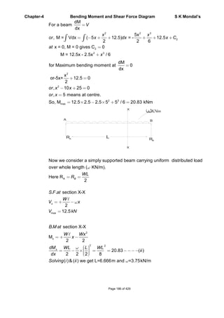
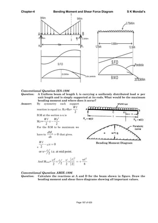
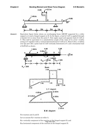
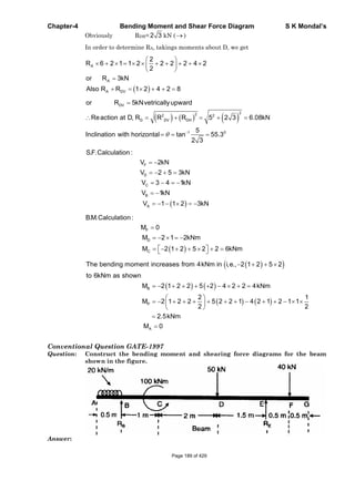
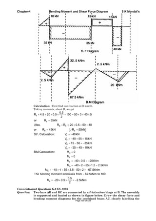
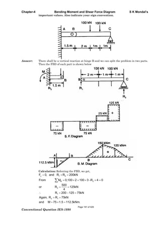
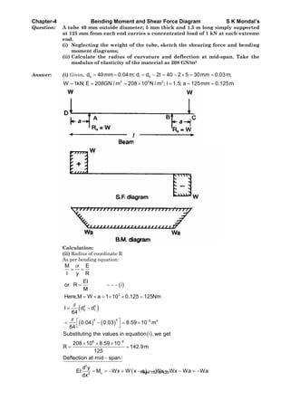
![Chapter-4 Bending Moment and Shear Force Diagram S K Mondal’s
4M 4M 2M
A C B D
20kN17.5kN/m
BMD
From the bending moment diagram we have seen that it is between A & C.
[If marks are more we should calculate exact point.]
Page 194 of 429](https://image.slidesharecdn.com/strengthofmaterialsbyskmondal-130102103545-phpapp02-150924095946-lva1-app6891/85/Strengthofmaterialsbyskmondal-130102103545-phpapp02-194-320.jpg)
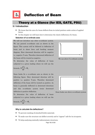
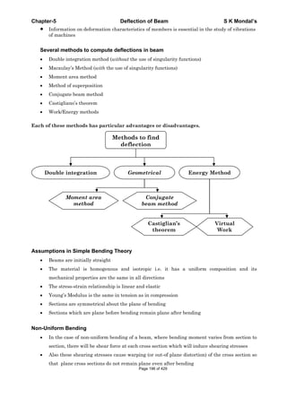
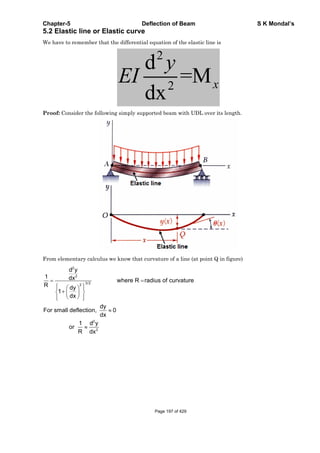
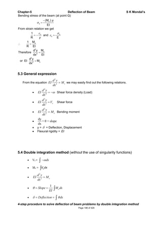
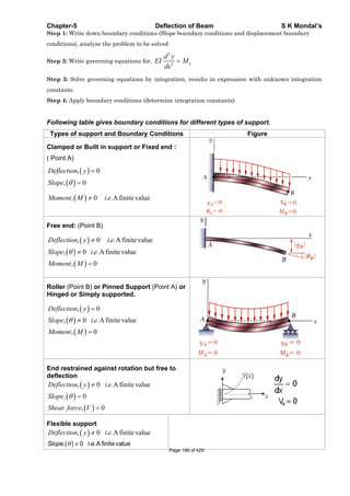
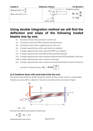
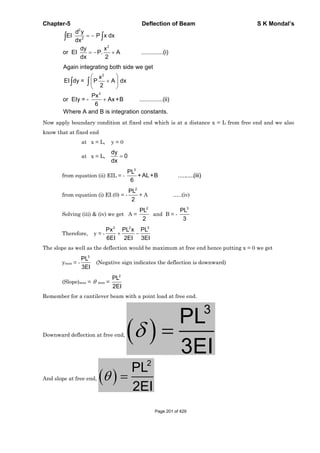
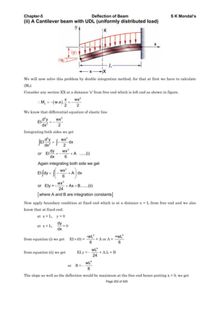
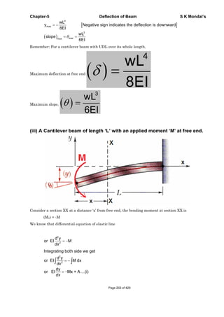
![Chapter-5 Deflection of Beam S K Mondal’s
2
Again integrating both side we get
EI dy = M x +A dx
Mx
or EI y Ax + B ...(ii)
2
Where A and B are integration constants.
2 2
2
2 2
applying boundary conditions in equation (i) &(ii)
dy
at x = L, 0 gives A = ML
dx
ML ML
at x = L, y = 0 gives B = ML
2 2
Mx MLx ML
Therefore deflection equation is y = -
2EI EI 2EI
Which is the equation of elastic curve.
Maximum deflection at free end
2
ML
=
2EI
(It is downward)
Maximum slope at free end
ML
EI
Let us take a funny example: A cantilever beam AB of length ‘L’ and uniform flexural rigidity EI
has a bracket BA (attached to its free end. A vertical downward force P is applied to free end C of the
bracket. Find the ratio a/L required in order that the deflection of point A is zero.
[ISRO – 2008]
We may consider this force ‘P’ and a moment (P.a) act on free end A of the cantilever beam.
Page 204 of 429](https://image.slidesharecdn.com/strengthofmaterialsbyskmondal-130102103545-phpapp02-150924095946-lva1-app6891/85/Strengthofmaterialsbyskmondal-130102103545-phpapp02-204-320.jpg)
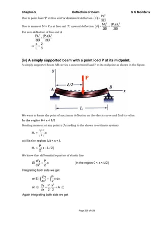
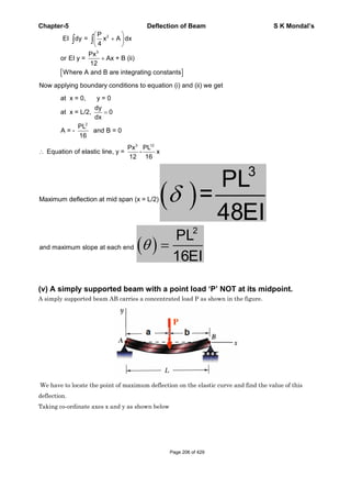
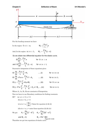
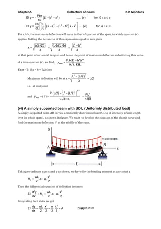
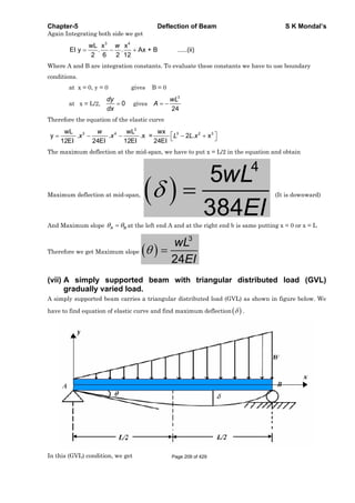
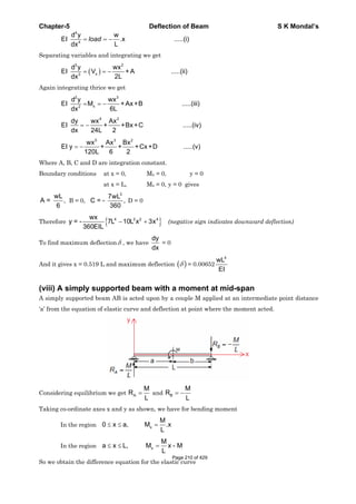
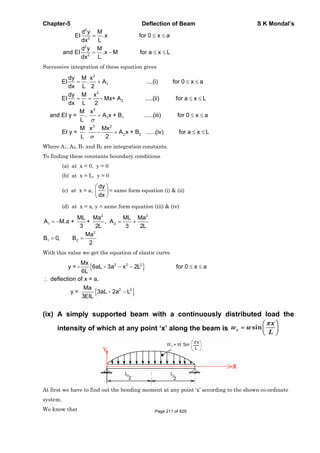
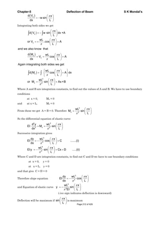
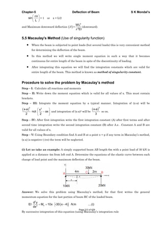
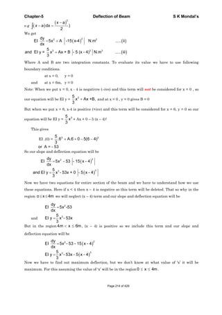
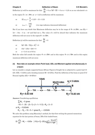
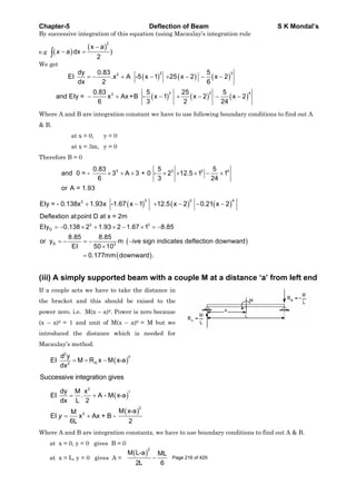
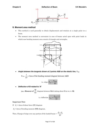
![Chapter-5 Deflection of Beam S K Mondal’s
Some typical bending moment diagram and their area (A) and distance of
C.G from one edge x is shown in the following table. [Note the distance
will be different from other end]
Shape BM Diagram Area Distance from C.G
1. Rectangle
A bh
2
b
x
2. Triangle
3
b
x
3. Parabola
4
b
x
4. Parabola
5.Cubic Parabola
6. y = k xn
7. Sine curve
Determination of Maximum slope and deflection
by Moment Area- Method
(i) A Cantilever beam with a point load at free end
Page 218 of 429](https://image.slidesharecdn.com/strengthofmaterialsbyskmondal-130102103545-phpapp02-150924095946-lva1-app6891/85/Strengthofmaterialsbyskmondal-130102103545-phpapp02-218-320.jpg)
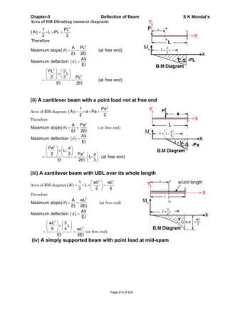
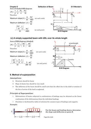
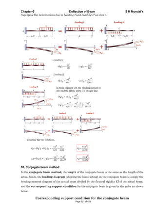
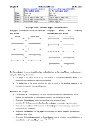
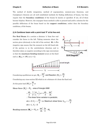
![Chapter-5 Deflection of Beam S K Mondal’s
OBJECTIVE QUESTIONS (GATE, IES, IAS)
Previous 20-Years GATE Questions
Beam Deflection
GATE-1. A lean elastic beam of given flexural
rigidity, EI, is loaded by a single force F
as shown in figure. How many boundary
conditions are necessary to determine
the deflected centre line of the beam?
(a) 5 (b) 4
(c) 3 (d) 2
[GATE-1999]
GATE-1. Ans. (d)
2
2
d y
EI M
dx
. Since it is second order differential equation so we need two boundary
conditions to solve it.
Double Integration Method
GATE-2. A simply supported beam carrying a concentrated load W at mid-span deflects
by 1 under the load. If the same beam carries the load W such that it is
distributed uniformly over entire length and undergoes a deflection 2 at the
mid span. The ratio 1: 2 is: [IES-1995; GATE-1994]
(a) 2: 1 (b) 2 : 1 (c) 1: 1 (d) 1: 2
GATE-2. Ans. (d)
3
1
Wl
48EI
and
4
3
2
W
5 l
5Wll
384EI 384EI
Therefore 1: 2 = 5: 8
GATE-3. A simply supported laterally loaded beam was found to deflect more than a
specified value. [GATE-2003]
Which of the following measures will reduce the deflection?
(a) Increase the area moment of inertia
(b) Increase the span of the beam
(c) Select a different material having lesser modulus of elasticity
(d) Magnitude of the load to be increased
GATE-3. Ans. (a) Maximum deflection ( ) =
3
Wl
48EI
To reduce, , increase the area moment of Inertia.
Page 225 of 429](https://image.slidesharecdn.com/strengthofmaterialsbyskmondal-130102103545-phpapp02-150924095946-lva1-app6891/85/Strengthofmaterialsbyskmondal-130102103545-phpapp02-225-320.jpg)
![Chapter-5 Deflection of Beam S K Mondal’s
Previous 20-Years IES Questions
Double Integration Method
IES-1. Consider the following statements: [IES-2003]
In a cantilever subjected to a concentrated load at the free end
1. The bending stress is maximum at the free end
2. The maximum shear stress is constant along the length of the beam
3. The slope of the elastic curve is zero at the fixed end
Which of these statements are correct?
(a) 1, 2 and 3 (b) 2 and 3 (c) 1 and 3 (d) 1 and 2
IES-1. Ans. (b)
IES-2. A cantilever of length L, moment of inertia I. Young's modulus E carries a
concentrated load W at the middle of its length. The slope of cantilever at the
free end is: [IES-2001]
(a)
2
2
WL
EI
(b)
2
4
WL
EI
(c)
2
8
WL
EI
(d)
2
16
WL
EI
IES-2. Ans. (c)
2
2
2
2 8
L
W
WL
EI EI
IES-3. The two cantilevers A
and B shown in the
figure have the same
uniform cross-section
and the same material.
Free end deflection of
cantilever 'A' is . [IES-2000]
The value of mid- span deflection of the cantilever ‘B’ is:
1 2
a b c d 2
2 3
IES-3. Ans. (c)
3 2 3
WL WL 5WL
L
3EI 2EI 6EI
2 3 3
mid
at x L
W 2Lx x 5WL
y
EI 2 6 6EI
IES-4. A cantilever beam of rectangular cross-section is subjected to a load W at its
free end. If the depth of the beam is doubled and the load is halved, the
deflection of the free end as compared to original deflection will be: [IES-1999]
(a) Half (b) One-eighth (c) One-sixteenth (d) Double
IES-4. Ans. (c)
3 3 3
3 3
12 4
Deflectionin cantilever
3 3
Wl Wl Wl
EI Eah Eah
3 3
3 3
4 1 4
If h is doubled, and W is halved, New deflection =
162 2
Wl Wl
EahEa h
IES-5. A simply supported beam of constant flexural rigidity and length 2L carries a
concentrated load 'P' at its mid-span and the deflection under the load is . If a
cantilever beam of the same flexural rigidity and length 'L' is subjected to load
'P' at its free end, then the deflection at the free end will be: [IES-1998]
1
a b c 2 d 4
2 Page 226 of 429](https://image.slidesharecdn.com/strengthofmaterialsbyskmondal-130102103545-phpapp02-150924095946-lva1-app6891/85/Strengthofmaterialsbyskmondal-130102103545-phpapp02-226-320.jpg)
![Chapter-5 Deflection of Beam S K Mondal’s
IES-5. Ans. (c)
3 3
2
forsimply supported beam
48 6
W L WL
EI EI
3
anddeflection for Cantilever 2
3
WL
EI
IES-6. Two identical cantilevers are
loaded as shown in the
respective figures. If slope at
the free end of the cantilever in
figure E is , the slope at free
and of the cantilever in figure
F will be:
Figure E Figure F
[IES-1997]
(a)
1
3
(b)
1
2
(c)
2
3
(d)
IES-6. Ans. (d) When a B. M is applied at the free end of cantilever,
2
/ 2
2
PL LML PL
EI EI EI
When a cantilever is subjected to a single concentrated load at free end, then
2
2
PL
EI
IES-7. A cantilever beam carries a load W uniformly distributed over its entire length.
If the same load is placed at the free end of the same cantilever, then the ratio
of maximum deflection in the first case to that in the second case will be:
[IES-1996]
(a) 3/8 (b) 8/3 (c) 5/8 (d) 8/5
IES-7. Ans. (a)
3 3
3
8 3 8
Wl Wl
EI EI
IES-8. The given figure shows a
cantilever of span 'L' subjected to
a concentrated load 'P' and a
moment 'M' at the free end.
Deflection at the free end is
given by
[IES-1996]
(a)
2 2
2 3
PL ML
EI EI
(b)
2 3
2 3
ML PL
EI EI
(c)
2 3
3 2
ML PL
EI EI
(d)
2 3
2 48
ML PL
EI EI
IES-8. Ans. (b)
IES-9. For a cantilever beam of length 'L', flexural rigidity EI and loaded at its free
end by a concentrated load W, match List I with List II and select the correct
answer. [IES-1996]
List I List II
A. Maximum bending moment 1. Wl
B. Strain energy 2. Wl2/2EI
C. Maximum slope 3. Wl3/3EI
D. Maximum deflection 4. W2l2/6EI
Codes: A B C D A B C D
(a) 1 4 3 2 (b) 1 4 2 3
(c) 4 2 1 3 (d) 4 3 1 2
IES-9. Ans. (b)
IES-10. Maximum deflection of a cantilever beam of length ‘l’ carrying uniformly
distributed load w per unit length will be: [IES- 2008]
Page 227 of 429](https://image.slidesharecdn.com/strengthofmaterialsbyskmondal-130102103545-phpapp02-150924095946-lva1-app6891/85/Strengthofmaterialsbyskmondal-130102103545-phpapp02-227-320.jpg)
![Chapter-5 Deflection of Beam S K Mondal’s
(a) wl4/ (EI) (b) w l4/ (4 EI) (c) w l4/ (8 EI) (d) w l4/ (384 EI)
[Where E = modulus of elasticity of beam material and I = moment of inertia of beam
cross-section]
IES-10. Ans. (c)
IES-11. A cantilever beam of length ‘l’ is subjected to a concentrated load P at a
distance of l/3 from the free end. What is the deflection of the free end of the
beam? (EI is the flexural rigidity) [IES-2004]
(a)
3
2
81
Pl
EI
(b)
3
3
81
Pl
EI
(c)
3
14
81
Pl
EI
(d)
3
15
81
Pl
EI
IES-11. Ans. (d)
A
3 3
2
2
max
3
3
Moment Area method gives us
1 2Pl 2l l 4
l
Area 2 3 3 3 9
x
EI EI
Pl 2 7 14 Pl
EI 9 9 81 EI
2l
W
Wa l a l 2l / 33
Alternatively Y
EI 2 6 EI 2 6
9 2Wl 4
EI 9 18
14 Wl
81 EI
IES-12. A 2 m long beam BC carries a single
concentrated load at its mid-span
and is simply supported at its ends
by two cantilevers AB = 1 m long and
CD = 2 m long as shown in the figure.
The shear force at end A of the
cantilever AB will be
(a) Zero (b) 40 kg
(c) 50 kg (d) 60 kg [IES-1997]
IES-12. Ans. (c) Reaction force on B and C is same 100/2 = 50 kg. And we know that shear force is
same throughout its length and equal to load at free end.
IES-13. Assertion (A): In a simply supported beam subjected to a concentrated load P at
mid-span, the elastic curve slope becomes zero under the load. [IES-2003]
Reason (R): The deflection of the beam is maximum at mid-span.
(a) Both A and R are individually true and R is the correct explanation of A
(b) Both A and R are individually true but R is NOT the correct explanation of A
(c) A is true but R is false
(d) A is false but R is true
IES-13. Ans. (a)
IES-14. At a certain section at a distance 'x' from one of the supports of a simply
supported beam, the intensity of loading, bending moment and shear force arc
Wx, Mx and Vx respectively. If the intensity of loading is varying continuously
along the length of the beam, then the invalid relation is: [IES-2000]
2
2
a Slope b c dx x x x
x x x x
x
M dM d M dV
Q V W W
V dx dx dx
IES-14. Ans. (a)
Page 228 of 429](https://image.slidesharecdn.com/strengthofmaterialsbyskmondal-130102103545-phpapp02-150924095946-lva1-app6891/85/Strengthofmaterialsbyskmondal-130102103545-phpapp02-228-320.jpg)
![Chapter-5 Deflection of Beam S K Mondal’s
IES-15. The bending moment equation, as a function of distance x measured from the
left end, for a simply supported beam of span L m carrying a uniformly
distributed load of intensity w N/m will be given by [IES-1999]
3 2
2 3 2
wL w wL w
a M= L-x - L-x Nm b M= x - x Nm
2 2 2 2
wL w wL wLx
c M= L-x - L-x Nm d M= x - Nm
2 2 2 2
IES-15. Ans. (b)
IES-16. A simply supported beam with width 'b' and depth ’d’ carries a central load W
and undergoes deflection at the centre. If the width and depth are
interchanged, the deflection at the centre of the beam would attain the value
[IES-1997]
2 3 3/2
a b c d
d d d d
b b b b
IES-16. Ans. (b) Deflection at center
3 3
3
Wl Wl
48EI bd
48E
12
3 3 3 2 2
2 23 3
Insecondcase,deflection
48
48 48
12 12
Wl Wl Wl d d
EI b bdb bd
E E
IES-17. A simply supported beam of rectangular section 4 cm by 6 cm carries a mid-
span concentrated load such that the 6 cm side lies parallel to line of action of
loading; deflection under the load is . If the beam is now supported with the 4
cm side parallel to line of action of loading, the deflection under the load will
be: [IES-1993]
(a) 0.44 (b) 0.67 (c) 1.5 (d) 2.25
IES-17. Ans. (d) Use above explanation
IES-18. A simply supported beam carrying a concentrated load W at mid-span deflects
by 1 under the load. If the same beam carries the load W such that it is
distributed uniformly over entire length and undergoes a deflection 2 at the
mid span. The ratio 1: 2 is: [IES-1995; GATE-1994]
(a) 2: 1 (b) 2 : 1 (c) 1: 1 (d) 1: 2
IES-18. Ans. (d)
3
1
Wl
48EI
and
4
3
2
W
5 l
5Wll
384EI 384EI
Therefore 1: 2 = 5: 8
Moment Area Method
IES-19. Match List-I with List-II and select the correct answer using the codes given
below the Lists: [IES-1997]
List-I List-II
A. Toughness 1. Moment area method
B. Endurance strength 2. Hardness
C. Resistance to abrasion 3. Energy absorbed before fracture in
a tension test
D. Deflection in a beam 4. Fatigue loading
Code: A B C D A B C D
(a) 4 3 1 2 (b) 4 3 2 1
(c) 3 4 2 1 (d) 3 4 1 2
IES-19. Ans. (c)
Page 229 of 429](https://image.slidesharecdn.com/strengthofmaterialsbyskmondal-130102103545-phpapp02-150924095946-lva1-app6891/85/Strengthofmaterialsbyskmondal-130102103545-phpapp02-229-320.jpg)
![Chapter-5 Deflection of Beam S K Mondal’s
Previous 20-Years IAS Questions
Slope and Deflection at a Section
IAS-1. Which one of the following is represented by the area of the S.F diagram from
one end upto a given location on the beam? [IAS-2004]
(a) B.M. at the location (b) Load at the location
(c) Slope at the location (d) Deflection at the location
IAS-1. Ans. (a)
Double Integration Method
IAS-2. Which one of the following is the correct statement? [IAS-2007]
If for a beam 0
dM
dx
for its whole length, the beam is a cantilever:
(a) Free from any load (b) Subjected to a concentrated load at its free end
(c) Subjected to an end moment (d) Subjected to a udl over its whole span
IAS-2. Ans. (c) udl or point load both vary with x. But
if we apply Bending Moment (M) = const.
and 0
dM
dx
IAS-3. In a cantilever beam, if the length is doubled while keeping the cross-section
and the concentrated load acting at the free end the same, the deflection at the
free end will increase by [IAS-1996]
(a) 2.66 times (b) 3 times (c) 6 times (d) 8 times
IAS-3. Ans. (d)
3
3
3 2 2
1 1
LPL
L 8
3EI L
Conjugate Beam Method
IAS-4. By conjugate beam method, the slope at any section of an actual beam is equal
to: [IAS-2002]
(a) EI times the S.F. of the conjugate beam (b) EI times the B.M. of the conjugate beam
(c) S.F. of conjugate beam (d) B.M. of the conjugate beam
IAS-4. Ans. (c)
IAS-5. I = 375 × 10-6 m4; l = 0.5 m
E = 200 GPa
Determine the stiffness of the
beam shown in the above figure
(a) 12 × 1010 N/m
(b) 10 × 1010 N/m
(c) 4 × 10¹⁰ N/m
(d) 8 × 10¹⁰ N/m
[IES-2002]
IAS-5. Ans. (c) Stiffness means required load for unit deformation. BMD of the given beam
Page 230 of 429](https://image.slidesharecdn.com/strengthofmaterialsbyskmondal-130102103545-phpapp02-150924095946-lva1-app6891/85/Strengthofmaterialsbyskmondal-130102103545-phpapp02-230-320.jpg)
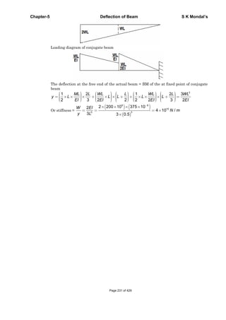
![Chapter-5 Deflection of Beam S K Mondal’s
Previous Conventional Questions with Answers
Conventional Question GATE-1999
Question: Consider the signboard mounting shown in figure below. The wind load
acting perpendicular to the plane of the figure is F = 100 N. We wish to limit
the deflection, due to bending, at point A of the hollow cylindrical pole of
outer diameter 150 mm to 5 mm. Find the wall thickness for the pole. [Assume
E = 2.0 X 10¹¹ N/m2]
Answer: Given: F = 100 N; d0 = 150 mm, 0.15 my = 5 mm; E = 2.0 X 1O11 N/m2
Thickness of pole, t
The system of signboard mounting can be considered as a cantilever loaded at A i.e. W
= 100 N and also having anticlockwise moment of M = 100 x 1 = 100 Nm at the free
end. Deflection of cantilever having concentrated load at the free end,
3 2
3 3
3
11 11
3 3
6 4
3 11 11
WL ML
y
3EI 2EI
100 5 100 5
5 10
3 2.0 10 I 2 2.0 10 I
1 100 5 100 5
or I 5.417 10 m
5 10 3 2.0 10 2 2.0 10
4 4
0 i
6 4 4
i
But I d d
64
5.417 10 0.15 d
64
i
0 i
or d 0.141m or 141 mm
d d 150 141
t 4.5mm
2 2
Conventional Question IES-2003
Question: Find the slope and deflection at the free end of a cantilever beam of length
6m as loaded shown in figure below, using method of superposition. Evaluate
their numerical value using E = 200 GPa, I = 1×10⁻⁴ m4 and W = 1 kN.
Page 232 of 429](https://image.slidesharecdn.com/strengthofmaterialsbyskmondal-130102103545-phpapp02-150924095946-lva1-app6891/85/Strengthofmaterialsbyskmondal-130102103545-phpapp02-232-320.jpg)
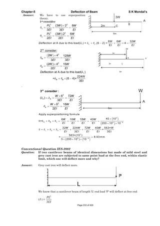
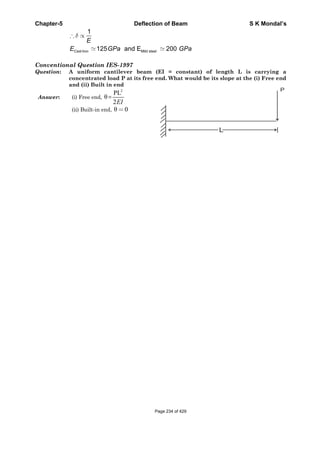
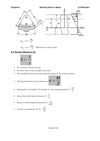
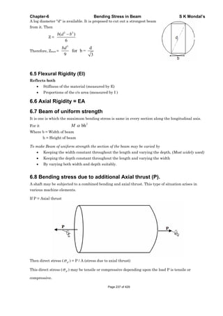
![Chapter-6 Bending Stress in Beam S K Mondal’s
And the bending stress ( b ) =
My
I
is varying linearly from zero at centre and extremum (minimum
or maximum) at top and bottom fibres.
If P is compressive then
At top fibre
P My
A I
(compressive)
At mid fibre
P
A
(compressive)
At bottom fibre
P
A
–
My
I
(compressive)
6.9 Load acting eccentrically to one axis
max
P e yP
A I
where ‘e’ is the eccentricity at which ‘P’ is act.
min
P e yP
A I
Condition for No tension in any section
For no tension in any section, the eccentricity must not exceed
2
2k
d
[Where d = depth of the section; k = radius of gyration of c/s]
For rectangular section (b x h) ,
6
h
e i.e load will be 2
3
h
e of the middle section.
For circular section of diameter ‘d’ ,
8
d
e i.e. diameter of the kernel, 2
4
d
e
For hollow circular section of diameter ‘d’ ,
2 2
8
D d
e
D
i.e. diameter of the kernel,
2 2
2 .
4
D d
e
D
Page 238 of 429](https://image.slidesharecdn.com/strengthofmaterialsbyskmondal-130102103545-phpapp02-150924095946-lva1-app6891/85/Strengthofmaterialsbyskmondal-130102103545-phpapp02-238-320.jpg)
![Chapter-6 Bending Stress in Beam S K Mondal’s
OBJECTIVE QUESTIONS (GATE, IES, IAS)
Previous 20-Years GATE Questions
Bending equation
GATE-1. A cantilever beam has the
square cross section 10mm ×
10 mm. It carries a transverse
load of 10 N. Considering only
the bottom fibres of the beam,
the correct representation of
the longitudinal variation of
the bending stress is:
[GATE-2005]
GATE-1. Ans. (a) x 4
10 x 0.005M My
M P.x or 60.(x) MPa
I y I 0.01
12
At x 0; 0
At x 1m; 60MPa
And it is linear as x
GATE-2. Two beams, one having square cross section and another circular cross-section,
are subjected to the same amount of bending moment. If the cross sectional
area as well as the material of both the beams are the same then [GATE-2003]
(a) Maximum bending stress developed in both the beams is the same
(b) The circular beam experiences more bending stress than the square one
(c) The square beam experiences more bending stress than the circular one
(d) As the material is same both the beams will experience same deformation
GATE-2. Ans. (b)
M E My
; or ;
I y I
2
2
sq cir3 4 3 3 3
3
a d
M M
6M 32M 4 M 22.27M d2 2
; a
1 4a d d a a
a.a
12 64
sq cir
Section Modulus
GATE-3. Match the items in Columns I and II. [GATE-2006]
Column-I Column-II
P. Addendum 1. Cam
Q. Instantaneous centre of velocity 2. BeamPage 239 of 429](https://image.slidesharecdn.com/strengthofmaterialsbyskmondal-130102103545-phpapp02-150924095946-lva1-app6891/85/Strengthofmaterialsbyskmondal-130102103545-phpapp02-239-320.jpg)
![Chapter-6 Bending Stress in Beam S K Mondal’s
R. Section modulus 3. Linkage
S. Prime circle 4. Gear
(a) P – 4, Q – 2, R – 3, S – l (b) P – 4, Q – 3, R – 2, S – 1
(c) P – 3, Q – 2, R – 1, S – 4 (d) P – 3, Q – 4, R – 1, S – 2
GATE-3. Ans. (b)
Combined direct and bending stress
GATE-4. For the component loaded with a force F as shown in the figure, the axial
stress at the corner point P is: [GATE-2008]
(a) 3
4
)3(
b
bLF
(b) 3
4
)3(
b
bLF
(c) 3
4
)43(
b
bLF
(d) 3
4
)23(
b
bLF
GATE-4. Ans. (d) Total Stress = Direct stress + Stress due to Moment
= 2 3
( )
4 2 ( )
12
P My F F L b b
A I b b b
Previous 20-Years IES Questions
Bending equation
IES-1. Beam A is simply supported at its ends and carries udl of intensity w over its
entire length. It is made of steel having Young's modulus E. Beam B is
cantilever and carries a udl of intensity w/4 over its entire length. It is made of
brass having Young's modulus E/2. The two beams are of same length and have
same cross-sectional area. If A and B denote the maximum bending stresses
developed in beams A and B, respectively, then which one of the following is
correct? [IES-2005]
(a) A/ B (b) A/ B < 1.0
(c) A/ B > 1.0 (d) A/ B depends on the shape of cross-section
IES-1. Ans. (d) Bending stress
My
, y and I both depends on the
I
A
B
Shape of cross sec tion so depends on the shape of cross sec tion
IES-2. If the area of cross-section of a circular section beam is made four times,
keeping the loads, length, support conditions and material of the beam
unchanged, then the qualities (List-I) will change through different factors
(List-II). Match the List-I with the List-II and select the correct answer using
the code given below the Lists: [IES-2005]
List-I List-II
A. Maximum BM 1. 8
Page 240 of 429](https://image.slidesharecdn.com/strengthofmaterialsbyskmondal-130102103545-phpapp02-150924095946-lva1-app6891/85/Strengthofmaterialsbyskmondal-130102103545-phpapp02-240-320.jpg)
![Chapter-6 Bending Stress in Beam S K Mondal’s
B. Deflection 2. 1
C. Bending Stress 3. 1/8
D. Section Modulus 4. 1/16
Codes: A B C D A B C D
(a) 3 1 2 4 (b) 2 4 3 1
(c) 3 4 2 1 (d) 2 1 3 4
IES-2. Ans. (b) Diameter will be double, D = 2d.
A. Maximum BM will be unaffected
B. deflection ratio
4
1
2
EI d 1
EI 4 16
C. Bending stress
3
2
4
1
M d / 2My d 1
or Bending stress ratio
I D 8d
64
D. Selection Modulus ratio
3
2 2 1
1 1 1
Z I y D
8
Z y I d
IES-3. Consider the following statements in case of beams: [IES-2002]
1. Rate of change of shear force is equal to the rate of loading at a particular
section
2. Rate of change of bending moment is equal to the shear force at a
particular suction.
3. Maximum shear force in a beam occurs at a point where bending moment
is either zero or bending moment changes sign
Which of the above statements are correct?
(a) 1 alone (b) 2 alone (c) 1 and 2 (d) 1, 2 and 3
IES-3. Ans. (c)
IES-4. Match List-I with List-II and select the correct answer using the code given
below the Lists: [IES-2006]
List-I (State of Stress) List-II (Kind of Loading)
1. Combined bending and torsion of circular
shaft
2. Torsion of circular shaft
3. Thin cylinder subjected to internal
pressure
4. Tie bar subjected to tensile force
Codes: A B C D A B C D
(a) 2 1 3 4 (b) 3 4 2 1
(c) 2 4 3 1 (d) 3 1 2 4
IES-4. Ans. (c)
Page 241 of 429](https://image.slidesharecdn.com/strengthofmaterialsbyskmondal-130102103545-phpapp02-150924095946-lva1-app6891/85/Strengthofmaterialsbyskmondal-130102103545-phpapp02-241-320.jpg)
![Chapter-6 Bending Stress in Beam S K Mondal’s
Section Modulus
IES-5. Two beams of equal cross-sectional area are subjected to equal bending
moment. If one beam has square cross-section and the other has circular
section, then [IES-1999]
(a) Both beams will be equally strong
(b) Circular section beam will be stronger
(c) Square section beam will be stronger
(d) The strength of the beam will depend on the nature of loading
IES-5. Ans. (b) If D is diameter of circle and 'a' the side of square section,
2 2 4
4
d a or d a
Z for circular section =
2 3 3
; and Z for square section =
32 64
d a a
IES-6. A beam cross-section is used in
two different orientations as
shown in the given figure:
Bending moments applied to the
beam in both cases are same. The
maximum bending stresses
induced in cases (A) and (B) are
related as:
(a) 4A B (b) 2A B
(c)
2
B
A (d)
4
B
A
[IES-1997]
IES-6. Ans. (b) Z for rectangular section is
2
6
bd
,
2
2
3 3
2 2,
6 24 6 12
A B
b bb bb b
Z Z
3 3
. . , 2
24 12
A A B B A B A B
b b
M Z Z or or
IES-7. A horizontal beam with square cross-section is simply supported with sides of
the square horizontal and vertical and carries a distributed loading that
produces maximum bending stress a in the beam. When the beam is placed
with one of the diagonals horizontal the maximum bending stress will be:
[IES-1993]
1
(a) (b) (c) 2 (d) 2
2
IES-7. Ans. (c) Bending stress =
M
Z
For rectangular beam with sides horizontal and vertical, Z =
3
6
a
For same section with diagonal horizontal, Z =
3
6 2
a
Ratio of two stresses = 2
IES-8. Which one of the following combinations of angles will carry the maximum
load as a column? [IES-1994]
Page 242 of 429](https://image.slidesharecdn.com/strengthofmaterialsbyskmondal-130102103545-phpapp02-150924095946-lva1-app6891/85/Strengthofmaterialsbyskmondal-130102103545-phpapp02-242-320.jpg)
![Chapter-6 Bending Stress in Beam S K Mondal’s
IES-8. Ans. (a)
IES-9. Assertion (A): For structures steel I-beams preferred to other shapes. [IES-1992]
Reason (R): In I-beams a large portion of their cross-section is located far from
the neutral axis.
(a) Both A and R are individually true and R is the correct explanation of A
(b) Both A and R are individually true but R is NOT the correct explanation of A
(c) A is true but R is false
(d) A is false but R is true
IES-9. Ans. (a)
Combined direct and bending stress
IES-10. Assertion (A): A column subjected to eccentric load will have its stress at
centroid independent of the eccentricity. [IES-1994]
Reason (R): Eccentric loads in columns produce torsion.
(a) Both A and R are individually true and R is the correct explanation of A
(b) Both A and R are individually true but R is NOT the correct explanation of A
(c) A is true but R is false
(d) A is false but R is true
IES-10. Ans. (c) A is true and R is false.
IES-11. For the configuration of loading shown in the given figure, the stress in fibre
AB is given by: [IES-1995]
(a) P/A (tensile) (b)
. .5
xx
P P e
A I
(Compressive)
(c)
. .5
xx
P P e
A I
(Compressive) (d) P/A (Compressive)
IES-11. Ans. (b) (compressive), (tensile)d x
x x
P My Pky
A I I
Page 243 of 429](https://image.slidesharecdn.com/strengthofmaterialsbyskmondal-130102103545-phpapp02-150924095946-lva1-app6891/85/Strengthofmaterialsbyskmondal-130102103545-phpapp02-243-320.jpg)
![Chapter-6 Bending Stress in Beam S K Mondal’s
IES-12. A column of square section 40 mm × 40
mm, fixed to the ground carries an
eccentric load P of 1600 N as shown in
the figure.
If the stress developed along the edge
CD is –1.2 N/mm2, the stress along the
edge AB will be:
(a) –1.2 N/mm2
(b) +1 N/mm2
(c) +0.8 N/mm2
(d) –0.8 N/mm2
[IES-1999]
IES-12. Ans. (d) Compressive stress at CD = 1.2 N/mm2 =
6 1600 6
1 1
1600 20
P e e
A b
26 1600
or 0.2. Sostressat 1 0.2 0.8 N/mm (com)
20 1600
e
AB
IES-13. A short column of symmetric cross-
section made of a brittle material is
subjected to an eccentric vertical load P
at an eccentricity e. To avoid tensile
stress in the short column, the
eccentricity e should be less than or equal
to:
(a) h/12 (b) h/6
(c) h/3 (d) h/2
[IES-2001]
IES-13. Ans. (b)
IES-14. A short column of external diameter D and internal diameter d carries an
eccentric load W. Toe greatest eccentricity which the load can have without
producing tension on the cross-section of the column would be: [IES-1999]
2 2 2 2 2 2
(a) (b) (c) (d)
8 8 8 8
D d D d D d D d
d D
IES-14. Ans. (c)
Page 244 of 429](https://image.slidesharecdn.com/strengthofmaterialsbyskmondal-130102103545-phpapp02-150924095946-lva1-app6891/85/Strengthofmaterialsbyskmondal-130102103545-phpapp02-244-320.jpg)
![Chapter-6 Bending Stress in Beam S K Mondal’s
Previous 20-Years IAS Questions
Bending equation
IAS-1. Consider the cantilever loaded as shown below: [IAS-2004]
What is the ratio of the maximum compressive to the maximum tensile stress?
(a) 1.0 (b) 2.0 (c) 2.5 (d) 3.0
IAS-1. Ans. (b) = compressive, Max
2
at lower end of A.
3
My M h
I I
tensile, max = at upper end of
3
M h
B
I
IAS-2. A 0.2 mm thick tape goes over a frictionless pulley of 25 mm diameter. If E of
the material is 100 GPa, then the maximum stress induced in the tape is:
[IAS 1994]
(a) 100 MPa (b) 200 MPa (c) 400 MPa (d) 800 MPa
IAS-2. Ans. (d)
R
E
y
Here y = 1.0
2
2.0
mm = 0.1 x 10⁻³ m, R =
2
25
mm = 12.5 x 10⁻³ m
or 3
33
105.12
101.010100
MPa = 800MPa
Section Modulus
IAS-3. A pipe of external diameter 3 cm and internal diameter 2 cm and of length 4 m
is supported at its ends. It carries a point load of 65 N at its centre. The
sectional modulus of the pipe will be: [IAS-2002]Page 245 of 429](https://image.slidesharecdn.com/strengthofmaterialsbyskmondal-130102103545-phpapp02-150924095946-lva1-app6891/85/Strengthofmaterialsbyskmondal-130102103545-phpapp02-245-320.jpg)
![Chapter-6 Bending Stress in Beam S K Mondal’s
(a)
365
64
cm (b)
365
32
cm (c)
365
96
cm (d)
365
128
cm
IAS-3. Ans. (c)
4 4
3
3 2
64Section modulus(z) cm
3
2
I
y
365
96
cm
IAS-4. A Cantilever beam of rectangular cross-section is 1m deep and 0.6 m thick. If
the beam were to be 0.6 m deep and 1m thick, then the beam would. [IAS-1999]
(a) Be weakened 0.5 times
(b) Be weakened 0.6 times
(c) Be strengthened 0.6 times
(d) Have the same strength as the original beam because the cross-sectional area
remains the same
IAS-4. Ans. (b)
3
3
1
I 0.6 1
z 1.2m
y 0.5
3
3
2
I 1 0.6
and z 0.72m
y 0.3
2
1
z 0.72
0.6times
z 1.2
IAS-5. A T-beam shown in the given figure is
subjected to a bending moment such that
plastic hinge forms. The distance of the
neutral axis from D is (all dimensions are
in mm)
(a) Zero
(b) 109 mm
(c) 125 mm
(d) 170 mm
[IAS-2001]
IAS-5. Ans. (b)
IAS-6. Assertion (A): I, T and channel sections are preferred for beams. [IAS-2000]
Reason(R): A beam cross-section should be such that the greatest possible
amount of area is as far away from the neutral axis as possible.
(a) Both A and R are individually true and R is the correct explanation of A
(b) Both A and R are individually true but R is NOT the correct explanation of A
(c) A is true but R is false
(d) A is false but R is true
IAS-6. Ans. (a) Because it will increase area moment of inertia, i.e. strength of the beam.Page 246 of 429](https://image.slidesharecdn.com/strengthofmaterialsbyskmondal-130102103545-phpapp02-150924095946-lva1-app6891/85/Strengthofmaterialsbyskmondal-130102103545-phpapp02-246-320.jpg)
![Chapter-6 Bending Stress in Beam S K Mondal’s
IAS-7. If the T-beam cross-section
shown in the given figure has
bending stress of 30 MPa in the
top fiber, then the stress in the
bottom fiber would be (G is
centroid)
(a) Zero
(b) 30 MPa
(c) –80 MPa
(d) 50 Mpa
[IAS-2000]
IAS-7. Ans. (c)
1 1
1 2 1
2 2
2
30
110 30 80
30
M
or y MPa
I y y y
As top fibre in tension so bottom fibre will be in compression.
IAS-8. Assertion (A): A square section is more economical in bending than the circular
section of same area of cross-section. [IAS-1999]
Reason (R): The modulus of the square section is less than of circular section of
same area of cross-section.
(a) Both A and R are individually true and R is the correct explanation of A
(b) Both A and R are individually true but R is NOT the correct explanation of A
(c) A is true but R is false
(d) A is false but R is true
IAS-8. ans. (c)
Bimetallic Strip
IAS-9. A straight bimetallic strip of copper and steel is heated. It is free at ends. The
strip, will: [IAS-2002]
(a) Expand and remain straight (b) Will not expand but will bend
(c) Will expand and bend also (d) Twist only
IAS-9. Ans. (c) As expansion of copper will be more than steel.
Combined direct and bending stress
IAS-10. A short vertical column having a
square cross-section is subjected to
an axial compressive force, centre
of pressure of which passes
through point R as shown in the
above figure. Maximum
compressive stress occurs at point
(a) S
(b) Q
(c) R
(d) P
[IAS-2002]
IAS-10. Ans. (a) As direct and bending both the stress is compressive here.
IAS-11. A strut's cross-sectional area A is subjected to load P a point S (h, k) as shown
in the given figure. The stress at the point Q (x, y) is: [IAS-2000]
Page 247 of 429](https://image.slidesharecdn.com/strengthofmaterialsbyskmondal-130102103545-phpapp02-150924095946-lva1-app6891/85/Strengthofmaterialsbyskmondal-130102103545-phpapp02-247-320.jpg)
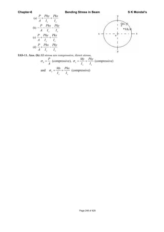
![Chapter-6 Bending Stress in Beam S K Mondal’s
Previous Conventional Questions with Answers
Conventional Question IES-2008
Question: A Simply supported beam AB of span length 4 m supports a uniformly
distributed load of intensity q = 4 kN/m spread over the entire span and a
concentrated load P = 2 kN placed at a distance of 1.5 m from left end A. The
beam is constructed of a rectangular cross-section with width b = 10 cm and
depth d = 20 cm. Determine the maximum tensile and compressive stresses
developed in the beam to bending.
Answer:
A
B
RA RB
X
1.5
4m
2KN 4kN/M
X
C/s
B=10cm
NA
A BR + R = 2 + 4×4.........(i)
A-R ×4 + 2×(4-1.5) + (4×4)×2=0.......(ii)
A B Aor R = 9.25 kN, R =18-R = 8.75 kN
if 0 x 2.5 m
x B
xM =R ×x - 4x. -2(x-2.5)
2
2 2
=8.75x - 2x - 2x + 5 = 6.75x - 2x + 5 ...(ii)
From (i) & (ii) we find out that bending movment at x = 2.1875 m in(i)
gives maximum bending movement
2
max
dM
[Just find for both the casses]
dx
M 8.25 2.1875 2 1875 9.57 7K kNm
Area movement of Inertia (I) =
3 3
5 40.1 0.2
6.6667 10
12 12
bh
m
Maximum distance from NA is y = 10 cm = 0.1m
3
2max 5
(9.57 10 ) 0.1
14.355
6.6667 10
My N MPa
mI
Therefore maximum tensile stress in the lowest point in the beam is 14.355 MPa and
maximum compressive stress in the topmost fiber of the beam is -14.355 MPa.
Conventional Question IES-2007
Question: A simply supported beam made of rolled steel joist (I-section: 450mm ×
200mm) has a span of 5 m and it carriers a central concentrated load W. The
flanges are strengthened by two 300mm × 20mm plates, one riveted to each
flange over the entire length of the flanges. The second moment of area of the
joist about the principal bending axis is 35060 cm4. CalculatePage 249 of 429](https://image.slidesharecdn.com/strengthofmaterialsbyskmondal-130102103545-phpapp02-150924095946-lva1-app6891/85/Strengthofmaterialsbyskmondal-130102103545-phpapp02-249-320.jpg)
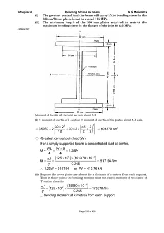
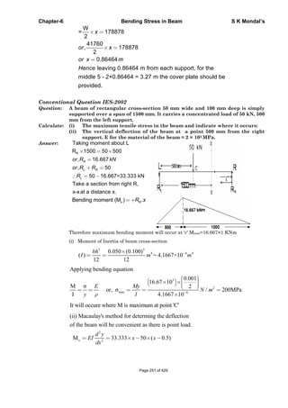
![Chapter-6 Bending Stress in Beam S K Mondal’s
2 2
2
1 22
2
3 3
1
1
Integrate both side we get
d 50
EI 33.333 ( 0.5)
2 2
x=0, y=0 gives c 0
x=1.5, y=0 gives
0=5.556×(1.5) 8.333 1 1.5
, 6.945
y x
x c x c
dx
at
at
c
or c
3 3
5 6 6
5.556 8.333( 0.5) 6.945 1 2.43
2.43
, m = -2.9167mm[downward so -ive]
(2×10 10 ) (4.1667 10 )
EIy x x
or y
Conventional Question AMIE-1997
Question: If the beam cross-section is rectangular having a width of 75 mm, determine
the required depth such that maximum bending stress induced in the beam
does not exceed 40 MN/m2
Answer: Given: b =75 mm =0·075 m, max =40 MN/m2
Depth of the beam, d: Figure below shows a rectangular section of width b = 0·075 m
and depth d metres. The bending is considered to take place about the horizontal
neutral axis N.A. shown in the figure. The maximum bending stress occurs at the outer
fibres of the rectangular section at a distance
d
2
above or below the neutral axis. Any
fibre at a distance y from N.A. is subjected to a bending stress,
My
I
, where I
denotes the second moment of area of the rectangular section about the N.A. i.e.
3
bd
12
.
At the outer fibres, y =
d
2
, the maximum bending stress there becomes
max 3 2
2
max
d
M
M2
i
bd bd
12 6
bd
or M . (ii)
6
For the condition of maximum strength i.e. maximum moment M, the product bd2 must
be a maximum, since max is constant for a given material. To maximize the quantity
bd2 we realise that it must be expressed in terms of one independent variable, say, b,
and we may do this from the right angle triangle relationship.
Page 252 of 429](https://image.slidesharecdn.com/strengthofmaterialsbyskmondal-130102103545-phpapp02-150924095946-lva1-app6891/85/Strengthofmaterialsbyskmondal-130102103545-phpapp02-252-320.jpg)
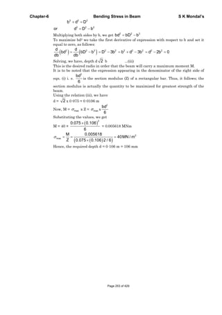
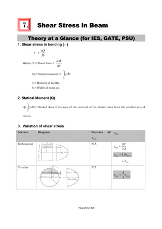
![Chapter-7 Shear Stress in Beam S K Mondal’s
Triangular
6
h
from N.A max 1.5 mean
NA = 1.33 mean
Trapezoidal
6
h
from N.A
Section Diagram
max
Uni form
I-Section
In Flange,
( max )
2
1
1
2 1
max
2 8
h
h
y
V
h
I
1 2
max hy
o
In Web
1
2 2 2
max 1 1 1( )
8y o
v
b h h th
It
1
22
1m 1
2 8
him y
vb
h h
It
4. Variation of shear stress for some more section [Asked in different examinations]
Non uniform I-Section Diagonally placed square section
L-section Hollow circle
T-section Cross
Page 255 of 429](https://image.slidesharecdn.com/strengthofmaterialsbyskmondal-130102103545-phpapp02-150924095946-lva1-app6891/85/Strengthofmaterialsbyskmondal-130102103545-phpapp02-255-320.jpg)
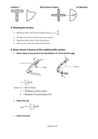
![Chapter-7 Shear Stress in Beam S K Mondal’s
OBJECTIVE QUESTIONS (GATE, IES, IAS)
Previous 20-Years GATE Questions
Shear Stress Variation
GATE-1. The transverse shear stress acting
in a beam of rectangular cross-
section, subjected to a transverse
shear load, is:
(a) Variable with maximum at the
bottom of the beam
(b) Variable with maximum at the
top of the beam
(c) Uniform
(d) Variable with maximum on the
neutral axis
[IES-1995, GATE-2008]
GATE-1. Ans (d) mean
2
3
max
GATE-2. The ratio of average shear stress to the maximum shear stress in a beam with a
square cross-section is: [GATE-1994, 1998]
2 3
(a) 1 (b) (c) (d) 2
3 2
GATE-2. Ans. (b)
max mean
3
2
Previous 20-Years IES Questions
Shear Stress Variation
IES-1. At a section of a beam, shear force is F with zero BM. The cross-section is
square with side a. Point A lies on neutral axis and point B is mid way between
neutral axis and top edge, i.e. at distance a/4 above the neutral axis. If A and
B denote shear stresses at points A and B, then what is the value of A / B?
[IES-2005]
(a) 0 (b) ¾ (c) 4/3 (d) None of above
IES-1. Ans. (c)
2
2
2
3
2 2 A
4 3 2
B 2
3
a a 3 VV y .a2 4VAy 3 V 42 aa 4y or
Ib 2 3a a 3 V aa . . a 412 2 4aPage 258 of 429](https://image.slidesharecdn.com/strengthofmaterialsbyskmondal-130102103545-phpapp02-150924095946-lva1-app6891/85/Strengthofmaterialsbyskmondal-130102103545-phpapp02-258-320.jpg)
![Chapter-7 Shear Stress in Beam S K Mondal’s
IES-2. A wooden beam of rectangular cross-section 10 cm deep by 5 cm wide carries
maximum shear force of 2000 kg. Shear stress at neutral axis of the beam
section is: [IES-1997]
(a) Zero (b) 40 kgf/cm2 (c) 60 kgf/cm2 (d) 80 kgf/cm2
IES-2. Ans. (c) Shear stress at neutral axis =
23 3 2000
60kg/cm
2 2 10 5
F
bd
IES-3. In case of a beam of circular cross-section subjected to transverse loading, the
maximum shear stress developed in the beam is greater than the average shear
stress by: [IES-2006; 2008]
(a) 50% (b) 33% (c) 25% (d) 10%
IES-3. Ans. (b) In the case of beams with circular cross-section, the ratio of the maximum shear
stress to average shear stress 4:3
IES-4. What is the nature of distribution of shear stress in a rectangular beam?
[IES-1993, 2004; 2008]
(a) Linear (b) Parabolic (c) Hyperbolic (d) Elliptic
IES-4. Ans. (b)
2
2
1
V h
y
4I 4
indicating a parabolic distribution of shear stress across the cross-
section.
IES-5. Which one of the following statements is correct? [IES 2007]
When a rectangular section beam is loaded transversely along the length, shear
stress develops on
(a) Top fibre of rectangular beam (b) Middle fibre of rectangular beam
(c) Bottom fibre of rectangular beam (d) Every horizontal plane
IES-5. Ans. (b)
IES-6. A beam having rectangular cross-section is subjected to an external loading.
The average shear stress developed due to the external loading at a particularPage 259 of 429](https://image.slidesharecdn.com/strengthofmaterialsbyskmondal-130102103545-phpapp02-150924095946-lva1-app6891/85/Strengthofmaterialsbyskmondal-130102103545-phpapp02-259-320.jpg)
![Chapter-7 Shear Stress in Beam S K Mondal’s
cross-section is avgt . What is the maximum shear stress developed at the same
cross-section due to the same loading? [IES-2009]
(a)
1
2
avgt (b) avgt (c)
3
2
avgt (d) 2 avgt
IES-6. Ans. (c)
Shear stress in a rectangular
beam, maximum shear stress,
max (average)
3F
1.5
2b. h
Shear stress in a circular beam, the
maximum shear stress,
max (average)
2
4F 4
33 d
4
IES-7. The transverse shear stress
acting in a beam of rectangular
cross-section, subjected to a
transverse shear load, is:
(a) Variable with maximum at the
bottom of the beam
(b) Variable with maximum at the
top of the beam
(c) Uniform
(d) Variable with maximum on the
neutral axis
[IES-1995, GATE-2008]
IES-7. Ans (d) mean
2
3
max
IES-8.
A cantilever is loaded by a concentrated load P at the free end as shown. The
shear stress in the element LMNOPQRS is under consideration. Which of the
following figures represents the shear stress directions in the cantilever?
[IES-2002]
Page 260 of 429](https://image.slidesharecdn.com/strengthofmaterialsbyskmondal-130102103545-phpapp02-150924095946-lva1-app6891/85/Strengthofmaterialsbyskmondal-130102103545-phpapp02-260-320.jpg)
![Chapter-7 Shear Stress in Beam S K Mondal’s
IES-8. Ans. (d)
IES-9. In I-Section of a beam subjected to transverse shear force, the maximum shear
stress is developed. [IES- 2008]
(a) At the centre of the web (b) At the top edge of the top flange
(c) At the bottom edge of the top flange (d) None of the above
IES-9. Ans. (a)
IES-10. The given figure (all
dimensions are in mm) shows
an I-Section of the beam. The
shear stress at point P (very
close to the bottom of the
flange) is 12 MPa. The stress at
point Q in the web (very close
to the flange) is:
(a) Indeterminable due to
incomplete data
(b) 60MPa
(c) 18 MPa
(d) 12 MPa
[IES-2001]
IES-10. Ans. (b)
IES-11. Assertion (A): In an I-Section beam subjected to concentrated loads, the
shearing force at any section of the beam is resisted mainly by the web portion.
Reason (R): Average value of the shearing stress in the web is equal to the
value of shearing stress in the flange. [IES-1995]
(a) Both A and R are individually true and R is the correct explanation of A
(b) Both A and R are individually true but R is NOT the correct explanation of A
(c) A is true but R is false
(d) A is false but R is true
IES-11. Ans. (c)
Shear stress distribution for different section
IES-12. The shear stress distribution over a beam cross-
section is shown in the figure above. The beam is of
(a) Equal flange I-Section
(b) Unequal flange I-Section
(c) Circular cross-section
(d) T-section
[IES-2003]
IES-12. Ans. (b)
Page 261 of 429](https://image.slidesharecdn.com/strengthofmaterialsbyskmondal-130102103545-phpapp02-150924095946-lva1-app6891/85/Strengthofmaterialsbyskmondal-130102103545-phpapp02-261-320.jpg)
![Chapter-7 Shear Stress in Beam S K Mondal’s
Previous 20-Years IAS Questions
Shear Stress Variation
IAS-1. Consider the following statements: [IAS-2007]
Two beams of identical cross-section but of different materials carry same
bending moment at a particular section, then
1. The maximum bending stress at that section in the two beams will be
same.
2. The maximum shearing stress at that section in the two beams will be
same.
3. Maximum bending stress at that section will depend upon the elastic
modulus of the beam material.
4. Curvature of the beam having greater value of E will be larger.
Which of the statements given above are correct?
(a) 1 and 2 only (b) 1, 3 and 4 (c) 1, 2 and 3 (d) 2, 3 and 4
IAS-1. Ans. (a) Bending stress =
My
I
and shear stress ( ) =
VAy
Ib
both of them does not depends
on material of beam.
IAS-2. In a loaded beam under bending [IAS-2003]
(a) Both the maximum normal and the maximum shear stresses occur at the skin
fibres
(b) Both the maximum normal and the maximum shear stresses occur the neutral axis
(c) The maximum normal stress occurs at the skin fibres while the maximum shear
stress occurs at the neutral axis
(d) The maximum normal stress occurs at the neutral axis while the maximum shear
stress occurs at the skin fibres
IAS-2. Ans. (c)
2
2
1
V h
y
4I 4
indicating a parabolic distribution of shear stress across the cross-
section.
Shear stress distribution for different section
IAS-3. Select the correct shear stress distribution diagram for a square beam with a
diagonal in a vertical position: [IAS-2002]
Page 262 of 429](https://image.slidesharecdn.com/strengthofmaterialsbyskmondal-130102103545-phpapp02-150924095946-lva1-app6891/85/Strengthofmaterialsbyskmondal-130102103545-phpapp02-262-320.jpg)
![Chapter-7 Shear Stress in Beam S K Mondal’s
IAS-3. Ans. (d)
IAS-4. The distribution of shear stress of a beam is shown in the given figure. The
cross-section of the beam is: [IAS-2000]
IAS-4. Ans. (b)
IAS-5. A channel-section of the beam shown in the given figure carries a uniformly
distributed load. [IAS-2000]
Assertion (A): The line of action of the load passes through the centroid of the
cross-section. The beam twists besides bending.
Reason (R): Twisting occurs since the line of action of the load does not pass
through the web of the beam.
(a) Both A and R are individually true and R is the correct explanation of A
(b) Both A and R are individually true but R is NOT the correct explanation of A
Page 263 of 429](https://image.slidesharecdn.com/strengthofmaterialsbyskmondal-130102103545-phpapp02-150924095946-lva1-app6891/85/Strengthofmaterialsbyskmondal-130102103545-phpapp02-263-320.jpg)
![Chapter-7 Shear Stress in Beam S K Mondal’s
Previous Conventional Questions with Answers
Conventional Question IES-2009
Q. (i)A cantilever of circular solid cross-section is fixed at one end and carries a
concentrated load P at the free end. The diameter at the free end is 200 mm
and increases uniformly to 400 mm at the fixed end over a length of 2 m. At
what distance from the free end will the bending stresses in the cantilever be
maximum? Also calculate the value of the maximum bending stress if the
concentrated load P = 30 kN [15-Marks]
Ans. We have
M
.... (i)
y I
Taking distance x from the free end we have
3
4
M = 30x kN.m = 30x × 10 N.m
x
y = 100 + 200 100
2
100 50x mm
d
and I =
64
Let d be the diameter at x from free end.
4
4
4
400 200
200 x
2
64
200 100x
mm
64
From equation (i), we have
3
3
4 12
3 12
100 50x 10
30x 10
200 100x 10
64
960x
200 100x 10 ...... (ii)
3 12960x
200 100x 10
d
For max , 0
dx
12
10 960
4 3
x 3 100 200 100x 1. 200 100x 0
- 300x + 200 + 100x = 0
x = 1m
Page 265 of 429](https://image.slidesharecdn.com/strengthofmaterialsbyskmondal-130102103545-phpapp02-150924095946-lva1-app6891/85/Strengthofmaterialsbyskmondal-130102103545-phpapp02-265-320.jpg)
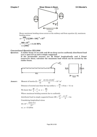
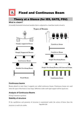
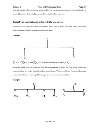
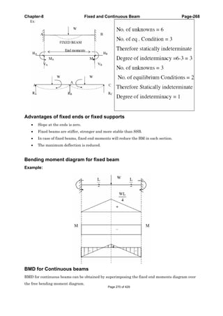
![Chapter-8 Fixed and Continuous Beam Page-270
OBJECTIVE QUESTIONS (GATE, IES, IAS)
Previous 20-Years IES Questions
Overhanging Beam
IES-1. An overhanging beam ABC is supported at points A and B, as shown in the
above figure. Find the maximum bending moment and the point where it
occurs. [IES-2009]
(a) 6 kN-m at the right support
(b) 6 kN-m at the left support
(c) 4.5 kN-m at the right support
(d) 4.5 kN-m at the midpoint
between the supports
IES-1. Ans. (a) Taking moment about A
B
B
B
A B
A
V 2 = 2 1 6 3
2V 2 18
V 10 kN
V V 2 6 8kN
V 8 10 2 kN
Maximum Bending Moment =
6 kN-m at the right support
IES-2. A beam of length 4 L is simply supported on two supports with equal overhangs
of L on either sides and carries three equal loads, one each at free ends and the
third at the mid-span. Which one of the following diagrams represents correct
distribution of shearing force on the beam? [IES-2004]
IES-2. Ans. (d)
Page 272 of 429](https://image.slidesharecdn.com/strengthofmaterialsbyskmondal-130102103545-phpapp02-150924095946-lva1-app6891/85/Strengthofmaterialsbyskmondal-130102103545-phpapp02-272-320.jpg)
![Chapter-8 Fixed and Continuous Beam Page-271
They use opposite sign conversions but for correct sign remember S.F & B.M of cantilever
is (-) ive.
IES-3. A horizontal beam carrying
uniformly distributed load is
supported with equal
overhangs as shown in the
given figure
The resultant bending moment at the mid-span shall be zero if a/b is: [IES-2001]
(a) 3/4 (b) 2/3 (c) 1/2 (d) 1/3
IES-3. Ans. (c)
Previous 20-Years IAS Questions
Overhanging Beam
IAS-1.
If the beam shown in the given figure is to have zero bending moment at its
middle point, the overhang x should be: [IAS-2000]
(a)
2
/ 4wl P (b)
2
/ 6wl P (c)
2
/ 8wl P (d)
2
/12wl P
IAS-1. Ans. (c)
2
c D
wl
R R P
Bending moment at mid point (M) =
2
0
2 4 2 2 8
D
wl l l l wl
R P x gives x
P
IAS-2. A beam carrying a uniformly distributed load rests on two supports 'b' apart
with equal overhangs 'a' at each end. The ratio b/a for zero bending moment at
mid-span is: [IAS-1997]
(a)
1
2
(b) 1 (c)
3
2
(d) 2
Page 273 of 429](https://image.slidesharecdn.com/strengthofmaterialsbyskmondal-130102103545-phpapp02-150924095946-lva1-app6891/85/Strengthofmaterialsbyskmondal-130102103545-phpapp02-273-320.jpg)
![Chapter-8 Fixed and Continuous Beam Page-272
IAS-2. Ans. (d)
(i) By similarity in the B.M diagram a must be b/2
(ii) By formula
2
2b
M a 0
2 4
gives a = b/2
IAS-3. A beam carries a uniformly distributed load and is supported with two equal
overhangs as shown in figure 'A'. Which one of the following correctly shows
the bending moment diagram of the beam? [IAS 1994]
IAS-3. Ans. (a)
Page 274 of 429](https://image.slidesharecdn.com/strengthofmaterialsbyskmondal-130102103545-phpapp02-150924095946-lva1-app6891/85/Strengthofmaterialsbyskmondal-130102103545-phpapp02-274-320.jpg)
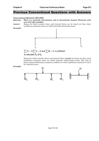
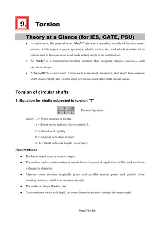
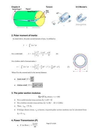
![Chapter-9 Torsion S K Mondal’s
• P (in hp) =
2
4500
NTπ
(1 hp = 75 Kgm/sec).
[Where N = rpm; T = Torque in N-m.]
5. Safe diameter of Shaft (d)
• Stiffness consideration
θ
=
T G
J L
• Shear Stress consideration
T
J R
τ
=
We take higher value of diameter of both cases above for overall safety if other parameters are given.
6. In twisting
• Solid shaft, maxτ = 3
16T
dπ
• Hollow shaft, maxτ = o
4 4
16Td
( )π −o id d
• Diameter of a shaft to have a maximum deflection "α " d = 4.9 × 4
α
TL
G
[Where T in N-mm, L in mm, G in N/mm2]
7. Comparison of solid and hollow shaft
• A Hollow shaft will transmit a greater torque than a solid shaft of the same weight & same
material because the average shear stress in the hollow shaft is smaller than the average
shear stress in the solid shaft
• max
max
( ) shaft 16
( ) shaft 15
τ
τ
=
holloow
solid o i
If solid shaft dia = D
D
Hollow shaft, d = D, d =
2
⎡ ⎤
⎢ ⎥
⎢ ⎥
⎣ ⎦
• Strength comparison (same weight, material, length and maxτ )
2
2
1
1
h
s
T n
T n n
+
=
−
Externaldiameter of hollow shaft
Where, n=
Internaldiameter of hollow shaft
[ONGC-2005]
• Weight comparison (same Torque, material, length and maxτ )
( )
( )
2 2/3
2/3
4
1
1
h
s
n nW
W n
−
=
−
Externaldiameter of hollow shaft
Where, n=
Internaldiameter of hollow shaft
[WBPSC-2003]
• Strain energy comparison (same weight, material, length and maxτ )
2
2
1h
s
U n
U n
+
= 2
1
1
n
= +
Page 278 of 429](https://image.slidesharecdn.com/strengthofmaterialsbyskmondal-130102103545-phpapp02-150924095946-lva1-app6891/85/Strengthofmaterialsbyskmondal-130102103545-phpapp02-278-320.jpg)
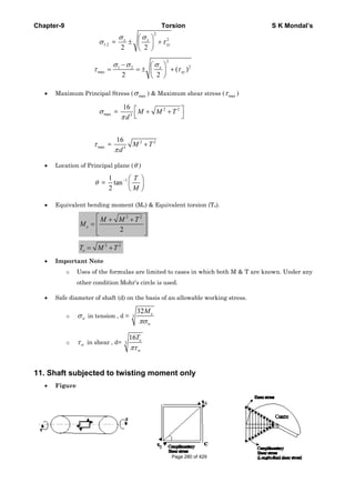
![Chapter-9 Torsion S K Mondal’s
• Normal force ( nF ) & Tangential for ( tF ) on inclined plane AB
[ ]
[ ]
sin + AC cos
× BC cos - AC sin
τ θ θ
τ θ θ
= − ×
=
n
t
F BC
F
• Normal stress ( nσ ) & Tangential stress (shear stress) ( tσ ) on inclined plane AB.
nσ = sin 2τ θ−
tσ = 2τ θcos
• Maximum normal & shear stress on AB
θ ( nσ )max τ max
0 0 +τ
45° –τ 0
90 0 –τ
135 +τ 0
• Important Note
• Principal stresses at a point on the surface of the shaft = +τ , -τ , 0
i.e 1,2 sin2σ τ θ= ±
• Principal strains
1 2 3(1 ); (1 ); 0
τ τ
μ μ∈ = + ∈ = − + ∈ =
E E
• Volumetric strain,
1 2 3 0∈ =∈ +∈ +∈ =v
• No change in volume for a shaft subjected to pure torque.
12. Torsional Stresses in Non-Circular Cross-section Members
• There are some applications in machinery for non-circular cross-section members and shafts
where a regular polygonal cross-section is useful in transmitting torque to a gear or pulley
that can have an axial change in position. Because no key or keyway is needed, the
possibility of a lost key is avoided.
• Saint Venant (1855) showed that maxτ in a rectangular b × c section bar occurs in the middle
of the longest side b and is of magnitude formula
max 2 2
1.8
3
/
T T
b cbc bc
τ
α
⎛ ⎞
= = +⎜ ⎟
⎝ ⎠
Where b is the longer side and α factor that is function of the ratio b/c.
The angle of twist is given by Page 281 of 429](https://image.slidesharecdn.com/strengthofmaterialsbyskmondal-130102103545-phpapp02-150924095946-lva1-app6891/85/Strengthofmaterialsbyskmondal-130102103545-phpapp02-281-320.jpg)
![Chapter-9 Torsion S K Mondal’s
3
Tl
bc G
θ
β
=
Where β is a function of the ratio b/c
Shear stress distribution in different cross-section
Rectangular c/s Elliptical c/s Triangular c/s
13. Torsion of thin walled tube
• For a thin walled tube
Shear stress,
02
τ =
T
A t
Angle of twist,
2 O
sL
A G
τ
φ =
[Where S = length of mean centre line, OA = Area enclosed by mean centre line]
• Special Cases
o For circular c/s
3 2
2 ; ; 2π π π= = =oJ r t A r S r
[r = radius of mean Centre line and t = wall thickness]
2
.
=
2 r 2
τ
π
∴ = =
o
T T r T
t J A t
3
2
τ
ϕ
π
= = =
o
TL L TL
GJ A JG r tG
o For square c/s of length of each side ‘b’ and thickness ‘t’
2
0
=4b
A b
S
=
o For elliptical c/s ‘a’ and ‘b’ are the half axis lengths.
0
3
( )
2
A ab
S a b ab
π
π
=
⎡ ⎤
≈ + −⎢ ⎥⎣ ⎦
Page 282 of 429](https://image.slidesharecdn.com/strengthofmaterialsbyskmondal-130102103545-phpapp02-150924095946-lva1-app6891/85/Strengthofmaterialsbyskmondal-130102103545-phpapp02-282-320.jpg)
![Chapter-9 Torsion S K Mondal’s
OBJECTIVE QUESTIONS (GATE, IES, IAS)
Previous 20-Years GATE Questions
Torsion Equation
GATE-1. A solid circular shaft of 60 mm diameter transmits a torque of 1600 N.m. The
value of maximum shear stress developed is: [GATE-2004]
(a) 37.72 MPa (b) 47.72 MPa (c) 57.72 MPa (d) 67.72 MPa
GATE-1. Ans. (a) 3
16T
d
τ
π
=
GATE-2. Maximum shear stress developed on the surface of a solid circular shaft under
pure torsion is 240 MPa. If the shaft diameter is doubled then the maximum
shear stress developed corresponding to the same torque will be: [GATE-2003]
(a) 120 MPa (b) 60 MPa (c) 30 MPa (d) 15 MPa
GATE-2. Ans. (c)
( )
3 3 3
16T 16T 16T 240
, 240 if diameter doubled d 2d, then 30MPa
8d d 2d
τ τ
π π π
′ ′= = = = = =
GATE-3. A steel shaft 'A' of diameter 'd' and length 'l' is subjected to a torque ‘T’ Another
shaft 'B' made of aluminium of the same diameter 'd' and length 0.5l is also
subjected to the same torque 'T'. The shear modulus of steel is 2.5 times the
shear modulus of aluminium. The shear stress in the steel shaft is 100 MPa. The
shear stress in the aluminium shaft, in MPa, is: [GATE-2000]
(a) 40 (b) 50 (c) 100 (d) 250
GATE-3. Ans. (c) 3
16T
d
τ
π
= as T & d both are same τ is same
GATE-4. For a circular shaft of diameter d subjected to torque T, the maximum value of
the shear stress is: [GATE-2006]
3 3 3 3
64 32 16 8
(a) (b) (c) (d)
T T T T
d d d dπ π π π
GATE-4. Ans. (c)
Power Transmitted by Shaft
GATE-5. The diameter of shaft A is twice the diameter or shaft B and both are made of
the same material. Assuming both the shafts to rotate at the same speed, the
maximum power transmitted by B is: [IES-2001; GATE-1994]
(a) The same as that of A (b) Half of A (c) 1/8th of A (d) 1/4th of A
GATE-5. Ans. (c)
3
3
2 N 16T d
Power, P T and or T
60 16d
π τπ
τ
π
= × = =
3
3d 2 N
or P orP d
16 60
τπ π
α= ×
Combined Bending and Torsion
GATE-6. A solid shaft can resist a bending moment of 3.0 kNm and a twisting moment of
4.0 kNm together, then the maximum torque that can be applied is: [GATE-1996]
(a) 7.0 kNm (b) 3.5 kNm (c)4.5 kNm (d) 5.0 kNm
GATE-6. Ans. (d) Equivalent torque ( ) 2 2 2 2
eT M T 3 4 5kNm= + = + =
Page 283 of 429](https://image.slidesharecdn.com/strengthofmaterialsbyskmondal-130102103545-phpapp02-150924095946-lva1-app6891/85/Strengthofmaterialsbyskmondal-130102103545-phpapp02-283-320.jpg)
![Chapter-9 Torsion S K Mondal’s
Comparison of Solid and Hollow Shafts
GATE-7. The outside diameter of a hollow shaft is twice its inside diameter. The ratio of
its torque carrying capacity to that of a solid shaft of the same material and the
same outside diameter is: [GATE-1993; IES-2001]
(a)
15
16
(b)
3
4
(c)
1
2
(d)
1
16
GATE-7. Ans. (a)
T G J
or T if is const. T J
J L R R
θ τ τ
τ α= = =
4
4
h h
4
D
D
32 2T J 15
T J 16
D
32
π
π
⎡ ⎤⎛ ⎞
−⎢ ⎥⎜ ⎟
⎝ ⎠⎢ ⎥⎣ ⎦= = =
Shafts in Series
GATE-8. A torque of 10 Nm is transmitted through a stepped shaft as shown in figure.
The torsional stiffness of individual sections of lengths MN, NO and OP are 20
Nm/rad, 30 Nm/rad and 60 Nm/rad respectively. The angular deflection between
the ends M and P of the shaft is: [GATE-2004]
(a) 0.5 rad (b) 1.0 rad (c) 5.0 rad (d) 10.0 rad
GATE-8. Ans. (b)
TL
We know that or T k. [let k tortional stiffness]
GJ
θ θ= = =
NO OPMN
MN NO OP
MN NO OP
T TT 10 10 10
1.0 rad
k k k 20 30 60
θ θ θ θ∴ = + + = + + = + + =
Shafts in Parallel
GATE-9. The two shafts AB and BC, of equal
length and diameters d and 2d, are
made of the same material. They are
joined at B through a shaft coupling,
while the ends A and C are built-in
(cantilevered). A twisting moment T is
applied to the coupling. If TA and TC
represent the twisting moments at the
ends A and C, respectively, then [GATE-2005]
(a) TC = TA (b) TC =8 TA (c) TC =16 TA (d) TA=16 TC
GATE-9. Ans. (c)
( )
C C C CA A A
AB BC A4 4
A A C C
T L T TT L T
or or or T
G J G J 16d 2d
32 32
θ θ
π π
= = = =
Previous 20-Years IES Questions
Torsion Equation
IES-1. Consider the following statements: [IES- 2008]
Maximum shear stress induced in a power transmitting shaft is:
1. Directly proportional to torque being transmitted.
2. Inversely proportional to the cube of its diameter.
Page 284 of 429](https://image.slidesharecdn.com/strengthofmaterialsbyskmondal-130102103545-phpapp02-150924095946-lva1-app6891/85/Strengthofmaterialsbyskmondal-130102103545-phpapp02-284-320.jpg)
![Chapter-9 Torsion S K Mondal’s
3. Directly proportional to its polar moment of inertia.
Which of the statements given above are correct?
(a) 1, 2 and 3 (b) 1 and 3 only (c) 2 and 3 only (d) 1 and 2 only
IES-1. Ans. (d) 3
T r 16T
J d
τ
π
×
= =
IES-2. A solid shaft transmits a torque T. The allowable shearing stress is τ . What is
the diameter of the shaft? [IES-2008]
3 3 3 3
16T 32T 16T T
(a) (b) (c) (d)
πτ πτ τ τ
IES-2. Ans. (a)
IES-3. Maximum shear stress developed on the surface of a solid circular shaft under
pure torsion is 240 MPa. If the shaft diameter is doubled, then what is the
maximum shear stress developed corresponding to the same torque? [IES-2009]
(a) 120 MPa (b) 60 MPa (c) 30 MPa (d) 15 MPa
IES-3. Ans. (c) Maximum shear stress = 3
16T
dπ
= 240 MPa = τ
Maximum shear stress developed when diameter is doubled
( )
τ τ⎛ ⎞
= = = = =⎜ ⎟π⎝ ⎠π
3 3
16 1 16T 240
30MPa
8 d 8 82d
IES-4. The diameter of a shaft is increased from 30 mm to 60 mm, all other conditions
remaining unchanged. How many times is its torque carrying capacity
increased? [IES-1995; 2004]
(a) 2 times (b) 4 times (c) 8 times (d) 16 times
IES-4. Ans. (c)
3
3
16T d
or T for same material const.
16d
τπ
τ τ
π
= = =
3 3
3 2 2
1 1
T d 60
T d or 8
T d 30
α
⎛ ⎞ ⎛ ⎞
∴ = = =⎜ ⎟ ⎜ ⎟
⎝ ⎠⎝ ⎠
IES-5. A circular shaft subjected to twisting moment results in maximum shear stress
of 60 MPa. Then the maximum compressive stress in the material is: [IES-2003]
(a) 30 MPa (b) 60 MPa (c) 90 MPa (d) 120 MPa
IES-5. Ans. (b)
IES-6. Angle of twist of a shaft of diameter ‘d’ is inversely proportional to [IES-2000]
(a) d (b) d2 (c) d3 (d) d4
IES-6. Ans. (d)
IES-7. A solid circular shaft is subjected to pure torsion. The ratio of maximum shear
to maximum normal stress at any point would be: [IES-1999]
(a) 1 : 1 (b) 1: 2 (c) 2: 1 (d) 2: 3
IES-7. Ans. (a) 3 3
16 32
Shear stress and normal stress
T T
d dπ π
= =
∴ Ratio of shear stress and normal stress = 1: 2
IES-8. Assertion (A): In a composite shaft having two concentric shafts of different
materials, the torque shared by each shaft is directly proportional to its polar
moment of inertia. [IES-1999]
Reason (R): In a composite shaft having concentric shafts of different
materials, the angle of twist for each shaft depends upon its polar moment of
inertia.
(a) Both A and R are individually true and R is the correct explanation of A
(b) Both A and R are individually true but R is NOT the correct explanation of A
(c) A is true but R is false
(d) A is false but R is true
Page 285 of 429](https://image.slidesharecdn.com/strengthofmaterialsbyskmondal-130102103545-phpapp02-150924095946-lva1-app6891/85/Strengthofmaterialsbyskmondal-130102103545-phpapp02-285-320.jpg)
![Chapter-9 Torsion S K Mondal’s
IES-8. Ans. (c)
IES-9. A shaft is subjected to torsion as shown. [IES-2002]
Which of the following figures represents the shear stress on the element
LMNOPQRS ?
IES-9. Ans. (d)
IES-10. A round shaft of diameter 'd' and
length 'l' fixed at both ends 'A' and
'B' is subjected to a twisting moment
'T’ at 'C', at a distance of 1/4 from A
(see figure). The torsional stresses in
the parts AC and CB will be:
(a) Equal
(b) In the ratio 1:3
(c) In the ratio 3 :1
(d) Indeterminate [IES-1997]
IES-10. Ans. (c)
T G GR 1
or
J R L L L
τ θ θ
τ τ= = = ∴ ∞
Hollow Circular Shafts
IES-11. One-half length of 50 mm diameter steel rod is solid while the remaining half is
hollow having a bore of 25 mm. The rod is subjected to equal and opposite
torque at its ends. If the maximum shear stress in solid portion is τ or, the
maximum shear stress in the hollow portion is: [IES-2003]
(a)
15
16
τ (b) τ (c)
4
3
τ (d)
16
15
τ
IES-11. Ans. (d)
τ τ
= =
T J
orT
J r r
;
2
τ τ ⎡ ⎤
= = =⎢ ⎥
⎣ ⎦
s h h
s h
s h
J J D
or r r
r r
Page 286 of 429](https://image.slidesharecdn.com/strengthofmaterialsbyskmondal-130102103545-phpapp02-150924095946-lva1-app6891/85/Strengthofmaterialsbyskmondal-130102103545-phpapp02-286-320.jpg)
![Chapter-9 Torsion S K Mondal’s
( )
4
4 4
32
32
π
τ τ τ
π
= × = ×
−
s
h
h
D
J
or
J D d
4 4
1 1 16
1525
1 1
50
τ τ τ
⎛ ⎞
= × = × = ⎜ ⎟
⎡ ⎤ ⎡ ⎤ ⎝ ⎠⎛ ⎞ ⎛ ⎞
− −⎢ ⎥ ⎢ ⎥⎜ ⎟ ⎜ ⎟
⎝ ⎠ ⎝ ⎠⎢ ⎥ ⎢ ⎥⎣ ⎦ ⎣ ⎦
d
D
Power Transmitted by Shaft
IES-12. In power transmission shafts, if the polar moment of inertia of a shaft is
doubled, then what is the torque required to produce the same angle of twist?
[IES-2006]
(a) 1/4 of the original value (b) 1/2 of the original value
(c) Same as the original value (d) Double the original value
IES-12. Ans. (d)
T G T.L
or Q if is const. T J if J is doubled then T is also doubled.
J L R G.J
θ τ
θ α= = =
IES-13. While transmitting the same power by a shaft, if its speed is doubled, what
should be its new diameter if the maximum shear stress induced in the shaft
remains same? [IES-2006]
(a)
1
2
of the original diameter (b)
1
2
of the original diameter
(c) 2 of the original diameter (d)
( )
1
3
1
2
of the original diameter
IES-13. Ans. (d) ( ) ( )Power (P) torque T angular speed ω= ×
( )
( )
( )
3 3 3
1 T 1
if P is const.T if or T T / 2
T 2
16 T / 216T d 1
or
dd 2d
ω
α
ω ω
σ
π π
′
′= = =
′
′⎛ ⎞
= = =⎜ ⎟
′ ⎝ ⎠
IES-14. For a power transmission shaft transmitting power P at N rpm, its diameter is
proportional to: [IES-2005]
(a)
1/3
P
N
⎛ ⎞
⎜ ⎟
⎝ ⎠
(b)
1/2
P
N
⎛ ⎞
⎜ ⎟
⎝ ⎠
(c)
2/3
P
N
⎛ ⎞
⎜ ⎟
⎝ ⎠
(d)
P
N
⎛ ⎞
⎜ ⎟
⎝ ⎠
IES-14. Ans. (a)
3
3
2 N 16T d
Power, P T and or T
60 16d
π τπ
τ
π
= × = =
1/33
3
2
d 2 N 480 P P
or P or d or d
16 60 NJ N
τπ π
α
π
⎛ ⎞
= × = ⎜ ⎟
⎝ ⎠
IES-15. A shaft can safely transmit 90 kW while rotating at a given speed. If this shaft
is replaced by a shaft of diameter double of the previous one and rotated at
half the speed of the previous, the power that can be transmitted by the new
shaft is: [IES-2002]
(a) 90 kW (b) 180 kW (c) 360 kW (d) 720 kW
IES-15. Ans. (c)
IES-16. The diameter of shaft A is twice the diameter or shaft B and both are made of
the same material. Assuming both the shafts to rotate at the same speed, the
maximum power transmitted by B is: [IES-2001; GATE-1994]
(a) The same as that of A (b) Half of A (c) 1/8th of A (d) 1/4th of A
IES-16. Ans. (c)
3
3
2 N 16T d
Power, P T and or T
60 16d
π τπ
τ
π
= × = =
3
3d 2 N
or P orP d
16 60
τπ π
α= ×
Page 287 of 429](https://image.slidesharecdn.com/strengthofmaterialsbyskmondal-130102103545-phpapp02-150924095946-lva1-app6891/85/Strengthofmaterialsbyskmondal-130102103545-phpapp02-287-320.jpg)
![Chapter-9 Torsion S K Mondal’s
IES-17. When a shaft transmits power through gears, the shaft experiences [IES-1997]
(a) Torsional stresses alone
(b) Bending stresses alone
(c) Constant bending and varying torsional stresses
(d) Varying bending and constant torsional stresses
IES-17. Ans. (d)
Combined Bending and Torsion
IES-18. The equivalent bending moment under combined action of bending moment M
and torque T is: [IES-1996; 2008; IAS-1996]
(a)
2 2
M T+ (b)
2 21
2
M M T⎡ ⎤+ +
⎣ ⎦
(c) [ ]
1
2
M T+ (d)
2 21
4
M T⎡ ⎤+
⎣ ⎦
IES-18. Ans. (b)
IES-19. A solid circular shaft is subjected to a bending moment M and twisting moment
T. What is the equivalent twisting moment Te which will produce the same
maximum shear stress as the above combination? [IES-1992; 2007]
(a) M2 + T2 (b) M + T (c) +2 2
M T (d) M – T
IES-19. Ans. (c) Te =
22
TM +
IES-20. A shaft is subjected to fluctuating loads for which the normal torque (T) and
bending moment (M) are 1000 N-m and 500 N-m respectively. If the combined
shock and fatigue factor for bending is 1.5 and combined shock and fatigue
factor for torsion is 2, then the equivalent twisting moment for the shaft is:
[IES-1994]
(a) 2000N-m (b) 2050N-m (c) 2100N-m (d) 2136 N-m
IES-20. Ans. (d) ( ) ( )
2 2
1.5 500 2 1000 2136 Nm= × + × =eqT
IES-21. A member is subjected to the combined action of bending moment 400 Nm and
torque 300 Nm. What respectively are the equivalent bending moment and
equivalent torque? [IES-1994; 2004]
(a) 450 Nm and 500 Nm (b) 900 Nm and 350 Nm
(c) 900 Nm and 500 Nm (d) 400 Nm and 500 Nm
IES-21. Ans. (a) ( )
2 2 2 2
e
M M T 400 400 300
Equivalent Bending Moment M 450N.m
2 2
+ + + +
= = =
( ) 2 2 2 2
eEquivalent torque T M T 400 300 500N.m= + = + =
IES-22. A shaft was initially subjected to bending moment and then was subjected to
torsion. If the magnitude of bending moment is found to be the same as that of
the torque, then the ratio of maximum bending stress to shear stress would be:
[IES-1993]
(a) 0.25 (b) 0.50 (c) 2.0 (d) 4.0
IES-22. Ans. (c) Use equivalent bending moment formula,
1st case: Equivalent bending moment (Me) = M
2nd case: Equivalent bending moment (Me) =
2 2
0 0
2 2
T T+ +
=Page 288 of 429](https://image.slidesharecdn.com/strengthofmaterialsbyskmondal-130102103545-phpapp02-150924095946-lva1-app6891/85/Strengthofmaterialsbyskmondal-130102103545-phpapp02-288-320.jpg)
![Chapter-9 Torsion S K Mondal’s
IES-23. A shaft is subjected to simultaneous action of a torque T, bending moment M
and an axial thrust F. Which one of the following statements is correct for this
situation? [IES-2004]
(a) One extreme end of the vertical diametral fibre is subjected to maximum
compressive stress only
(b) The opposite extreme end of the vertical diametral fibre is subjected to
tensile/compressive stress only
(c) Every point on the surface of the shaft is subjected to maximum shear stress only
(d) Axial longitudinal fibre of the shaft is subjected to compressive stress only
IES-23. Ans. (a)
IES-24. For obtaining the
maximum shear stress
induced in the shaft
shown in the given
figure, the torque
should be equal to
( )
1
2 2
2
1
2 22
2
(a) (b)
(c)
2
(d)
2
T Wl T
wL
Wl
wL
Wl T
+
⎡ ⎤⎛ ⎞
+⎢ ⎥⎜ ⎟
⎝ ⎠⎢ ⎥⎣ ⎦
⎡ ⎤⎧ ⎫
⎢ ⎥+ +⎨ ⎬
⎢ ⎥⎩ ⎭⎣ ⎦ [IES-1999]
IES-24. Ans. (d) Bending Moment, M =
2
2
+
wL
Wl
IES-25. Bending moment M and torque is applied on a solid circular shaft. If the
maximum bending stress equals to maximum shear stress developed, them M is
equal to: [IES-1992]
(a) (b) (c) 2 (d) 4
2
T
T T T
IES-25. Ans. (a) 3
32 M
d
σ
π
×
= and 3
16T
d
τ
π
=
IES-26. A circular shaft is subjected to the combined action of bending, twisting and
direct axial loading. The maximum bending stress σ, maximum shearing force
3σ and a uniform axial stress σ(compressive) are produced. The maximum
compressive normal stress produced in the shaft will be: [IES-1998]
(a) 3 σ (b) 2 σ (c) σ (d) Zero
IES-26. Ans. (a) Maximum normal stress = bending stress σ + axial stress (σ) = 2 σ
We have to take maximum bending stress σ is (compressive)
The maximum compressive normal stress =
2
2
2 2
σ σ
τ
⎛ ⎞
− +⎜ ⎟
⎝ ⎠
b b
xy
( )
2
22 2
3 3
2 2
σ σ
σ σ
− −⎛ ⎞
= − + = −⎜ ⎟
⎝ ⎠
IES-27. Which one of the following statements is correct? Shafts used in heavy duty
speed reducers are generally subjected to: [IES-2004]
(a) Bending stress only
Page 289 of 429](https://image.slidesharecdn.com/strengthofmaterialsbyskmondal-130102103545-phpapp02-150924095946-lva1-app6891/85/Strengthofmaterialsbyskmondal-130102103545-phpapp02-289-320.jpg)
![Chapter-9 Torsion S K Mondal’s
(b) Shearing stress only
(c) Combined bending and shearing stresses
(d) Bending, shearing and axial thrust simultaneously
IES-27. Ans. (c)
Comparison of Solid and Hollow Shafts
IES-28. The ratio of torque carrying capacity of a solid shaft to that of a hollow shaft is
given by: [IES-2008]
( ) ( )
1
4 4 4 4
(a) 1 K (b) 1 K (c)K (d)1/ K
−
− −
Where K = i
o
D
D
; Di = Inside diameter of hollow shaft and Do = Outside diameter of hollow
shaft. Shaft material is the same.
IES-28. Ans. (b) τ should be same for both hollow and solid shaft
( )
( )
1
44
s s o sh i
4 4
4 4 4 h h oo i
o o i
1
4s
h
T T D TT D
1
T T DD DD D D
32 32
T
1 k
T
−
−
⎛ ⎞⎛ ⎞
⎜ ⎟= ⇒ = ⇒ = − ⎜ ⎟
π π ⎜ ⎟− ⎝ ⎠− ⎝ ⎠
∴ −
IES-29. A hollow shaft of outer dia 40 mm and inner dia of 20 mm is to be replaced by a
solid shaft to transmit the same torque at the same maximum stress. What
should be the diameter of the solid shaft? [IES 2007]
(a) 30 mm (b) 35 mm (c) 10×(60)1/3 mm (d) 10×(20)1/3 mm
IES-29. Ans. (c) Section modules will be same
H
H
J
R
= s
s
J
R
or
2
40
)2040(
64
44
−
π
=
64
π
×
2
4
d
d
or, d3 = (10)3 ×60 or d = 10 3
60 mm
IES-30. The diameter of a solid shaft is D. The inside and outside diameters of a hollow
shaft of same material and length are
3
D
and
3
2D
respectively. What is the
ratio of the weight of the hollow shaft to that of the solid shaft? [IES 2007]
(a) 1:1 (b) 1: 3 (c) 1:2 (d) 1:3
IES-30. Ans. (a)
S
H
W
W
= 1
4
33
4
4
2
22
=
×××
×××⎟⎟
⎠
⎞
⎜⎜
⎝
⎛
−
gLD
gL
DD
ρ
π
ρ
π
IES-31. What is the maximum torque transmitted by a hollow shaft of external radius R
and internal radius r? [IES-2006]
(a) ( )3 3
16
sR r f
π
− (b) ( )4 4
2
sR r f
R
π
− (c) ( )4 4
8
sR r f
R
π
− (d)
4 4
32
s
R r
f
R
π ⎛ ⎞−
⎜ ⎟
⎝ ⎠
( sf = maximum shear stress in the shaft material)
IES-31. Ans. (b)
( )
( )
4 4
4 4s
s s s
R rfT J 2or T f f R r .f .
J R R R 2R
π
π−
= = × = × = −
IES-32. A hollow shaft of the same cross-sectional area and material as that of a solid
shaft transmits: [IES-2005]
Page 290 of 429](https://image.slidesharecdn.com/strengthofmaterialsbyskmondal-130102103545-phpapp02-150924095946-lva1-app6891/85/Strengthofmaterialsbyskmondal-130102103545-phpapp02-290-320.jpg)
![Chapter-9 Torsion S K Mondal’s
(a) Same torque (b) Lesser torque
(c) More torque (d) Cannot be predicted without more data
IES-32. Ans. (c)
2
H H
2
S H
T Dn 1
, Where n
T dn n 1
+
= =
−
IES-33. The outside diameter of a hollow shaft is twice its inside diameter. The ratio of
its torque carrying capacity to that of a solid shaft of the same material and the
same outside diameter is: [GATE-1993; IES-2001]
(a)
15
16
(b)
3
4
(c)
1
2
(d)
1
16
IES-33. Ans. (a)
T G J
or T if is const. T J
J L R R
θ τ τ
τ α= = =
4
4
h h
4
D
D
32 2T J 15
T J 16
D
32
π
π
⎡ ⎤⎛ ⎞
−⎢ ⎥⎜ ⎟
⎝ ⎠⎢ ⎥⎣ ⎦= = =
IES-34. Two hollow shafts of the same material have the same length and outside
diameter. Shaft 1 has internal diameter equal to one-third of the outer
diameter and shaft 2 has internal diameter equal to half of the outer diameter.
If both the shafts are subjected to the same torque, the ratio of their twists
1 2/θ θ will be equal to: [IES-1998]
(a) 16/81 (b) 8/27 (c) 19/27 (d) 243/256
IES-34. Ans. (d)
4
4 1
1
1
4
42 1
1
21 243
256
3
d
d
Q
Q
J Q d
d
⎛ ⎞−⎜ ⎟
⎝ ⎠∞ ∴ = =
⎛ ⎞−⎜ ⎟
⎝ ⎠
IES-35. Maximum shear stress in a solid shaft of diameter D and length L twisted
through an angle θ is τ. A hollow shaft of same material and length having
outside and inside diameters of D and D/2 respectively is also twisted through
the same angle of twist θ. The value of maximum shear stress in the hollow
shaft will be: [IES-1994; 1997]
( ) ( ) ( ) ( )
16 8 4
a b c d
15 7 3
τ τ τ τ
IES-35. Ans. (d)
T G G.R.
or if is const. R
J L R L
θ τ θ
τ θ τ α= = = and outer diameter is same in both
the cases.
Note: Required torque will be different.
IES-36. A solid shaft of diameter 'D' carries a twisting moment that develops maximum
shear stress τ. If the shaft is replaced by a hollow one of outside diameter 'D'
and inside diameter D/2, then the maximum shear stress will be: [IES-1994]
(a) 1.067 τ (b) 1.143 τ (c) 1.333 τ (d) 2 τ
IES-36. Ans. (a)
T G TR 1
or if T is const.
J L R J J
θ τ
τ τ α= = =
4
h
4
h 4
J D 16
1.06666
J 15D
D
2
τ
τ
= = = =
⎛ ⎞
− ⎜ ⎟
⎝ ⎠
IES-37. A solid shaft of diameter 100 mm, length 1000 mm is subjected to a twisting
moment 'T’ The maximum shear stress developed in the shaft is 60 N/mm2. A
hole of 50 mm diameter is now drilled throughout the length of the shaft. To
Page 291 of 429](https://image.slidesharecdn.com/strengthofmaterialsbyskmondal-130102103545-phpapp02-150924095946-lva1-app6891/85/Strengthofmaterialsbyskmondal-130102103545-phpapp02-291-320.jpg)
![Chapter-9 Torsion S K Mondal’s
develop a maximum shear stress of 60 N/mm2 in the hollow shaft, the torque 'T’
must be reduced by: [IES-1998]
(a) T/4 (b) T/8 (c) T/12 (d)T/16
IES-37. Ans. (d)
( )
43 4
16 32( / 2) 15
or
16/ 2
s
Tr T T d T
J d Td d
τ
π
′ ′
= = = =
−
1
Reduction
16
∴ =
IES-38. Assertion (A): A hollow shaft will transmit a greater torque than a solid shaft of
the same weight and same material. [IES-1994]
Reason (R): The average shear stress in the hollow shaft is smaller than the
average shear stress in the solid shaft.
(a) Both A and R are individually true and R is the correct explanation of A
(b) Both A and R are individually true but R is NOT the correct explanation of A
(c) A is true but R is false
(d) A is false but R is true
IES-38. Ans. (a)
IES-39. A hollow shaft is subjected to torsion. The shear stress variation in the shaft
along the radius is given by: [IES-1996]
IES-39. Ans. (c)
Shafts in Series
IES-40. What is the total angle of
twist of the stepped
shaft subject to torque T
shown in figure given
above?
(a) 4
16 lT
Gdπ
(b) 4
38 lT
Gdπ
(c) 4
64 lT
Gdπ
(d) 4
66 lT
Gdπ [IES-2005]
IES-40. Ans. (d)
( )
[ ]1 2 4 4 4
4
T 2l T l Tl 66Tl
64 2
d Gd GdG 2dG.
3232
θ θ θ
ππ
× ×
= + = + = + =
× ×
Shafts in Parallel
IES-41. For the two shafts connected in parallel, find which statement is true?
(a) Torque in each shaft is the same [IES-1992]
(b) Shear stress in each shaft is the same
(c) Angle of twist of each shaft is the same
(d) Torsional stiffness of each shaft is the same
IES-41. Ans. (c)
Page 292 of 429](https://image.slidesharecdn.com/strengthofmaterialsbyskmondal-130102103545-phpapp02-150924095946-lva1-app6891/85/Strengthofmaterialsbyskmondal-130102103545-phpapp02-292-320.jpg)
![Chapter-9 Torsion S K Mondal’s
IES-42. A circular section rod ABC is fixed at ends A and C. It is subjected to torque T
at B. AB = BC = L and the polar moment of inertia of portions AB and BC are 2
J and J respectively. If G is the modulus of rigidity, what is the angle of twist at
point B? [IES-2005]
(a)
3
TL
GJ
(b)
2
TL
GJ
(c)
TL
GJ
(d)
2TL
GJ
IES-42. Ans. (a) AB BCθ θ=
BC.AB
AB BC
AB BC BC
B AB
T LT L
or or T 2T
G.2J G.J
T T T or T T / 3
T L TL
or Q Q .
3 GJ 3GJ
= =
+ = =
= = =
IES-43. A solid circular rod AB of diameter D and length L is fixed at both ends. A
torque T is applied at a section X such that AX = L/4 and BX = 3L/4. What is the
maximum shear stress developed in the rod? [IES-2004]
(a) 3
16T
Dπ
(b) 3
12T
Dπ
(c) 3
8T
Dπ
(d) 3
4T
Dπ
IES-43. Ans. (b) AX XB A B
B
A.
A B A
A
max 4
3
&T T T
3L
T
T L / 4 4or
GJ GJ
3T
or T 3T or T ,
4
3
16 T
16T 12T4
D3 D3D
θ θ
τ
π ππ
= + =
×
=
= =
× ×
= = =
IES-44. Two shafts are shown in
the above figure. These
two shafts will be
torsionally equivalent to
each other if their
(a) Polar moment of inertias
are the same
(b) Total angle of twists are
the same
(c) Lengths are the same
(d) Strain energies are the
same [IES-1998]
IES-44. Ans. (b)
Previous 20-Years IAS Questions
Torsion Equation
IAS-1. Assertion (A): In theory of torsion, shearing strains increase radically away
from the longitudinal axis of the bar. [IAS-2001]
Reason (R): Plane transverse sections before loading remain plane after the
torque is applied.
Page 293 of 429](https://image.slidesharecdn.com/strengthofmaterialsbyskmondal-130102103545-phpapp02-150924095946-lva1-app6891/85/Strengthofmaterialsbyskmondal-130102103545-phpapp02-293-320.jpg)
![Chapter-9 Torsion S K Mondal’s
(a) Both A and R are individually true and R is the correct explanation of A
(b) Both A and R are individually true but R is NOT the correct explanation of A
(c) A is true but R is false
(d) A is false but R is true
IAS-1. Ans. (b)
IAS-2. The shear stress at a point in a shaft subjected to a torque is: [IAS-1995]
(a) Directly proportional to the polar moment of inertia and to the distance of the point
form the axis
(b) Directly proportional to the applied torque and inversely proportional to the polar
moment of inertia.
(c) Directly proportional to the applied torque and polar moment of inertia
(d) inversely proportional to the applied torque and the polar moment of inertia
IAS-2. Ans. (b)
RJ
T τ
=
IAS-3. If two shafts of the same length, one of which is hollow, transmit equal torque
and have equal maximum stress, then they should have equal. [IAS-1994]
(a) Polar moment of inertia (b) Polar modulus of section
(c) Polar moment of inertia (d) Angle of twist
IAS-3. Ans. (b)
RJ
T τ
= Here T & τ are same, so
J
R
should be same i.e. polar modulus of section will
be same.
Hollow Circular Shafts
IAS-4. A hollow circular shaft having outside diameter 'D' and inside diameter ’d’
subjected to a constant twisting moment 'T' along its length. If the maximum
shear stress produced in the shaft is sσ then the twisting moment 'T' is given
by: [IAS-1999]
(a)
4 4
4
8
s
D d
D
π
σ
−
(b)
4 4
4
16
s
D d
D
π
σ
−
(c)
4 4
4
32
s
D d
D
π
σ
−
(d)
4 4
4
64
s
D d
D
π
σ
−
IAS-4. Ans. (b)
( ) ( )
4 4
4 4
s
s
D d D dT G J 32gives T
DJ L R R 16 D
2
π
σ
θ τ τ π
σ
× − −
= = = = =
Torsional Rigidity
IAS-5. Match List-I with List-II and select the correct answer using the codes given
below the lists: [IAS-1996]
List-I (Mechanical Properties) List-II ( Characteristics)
A. Torsional rigidity 1. Product of young's modulus and second
moment of area about the plane of
bending
B. Modulus of resilience 2. Strain energy per unit volume
C. Bauschinger effect 3. Torque unit angle of twist
D. Flexural rigidity 4. Loss of mechanical energy due to local
yielding
Codes: A B C D A B C D
(a) 1 3 4 2 (b) 3 2 4 1
(c) 2 4 1 3 (d) 3 1 4 2
IAS-5. Ans. (b)
IAS-6. Assertion (A): Angle of twist per unit length of a uniform diameter shaft
depends upon its torsional rigidity. [IAS-2004]
Reason (R): The shafts are subjected to torque only.
(a) Both A and R are individually true and R is the correct explanation of A
(b) Both A and R are individually true but R is NOT the correct explanation of A
Page 294 of 429](https://image.slidesharecdn.com/strengthofmaterialsbyskmondal-130102103545-phpapp02-150924095946-lva1-app6891/85/Strengthofmaterialsbyskmondal-130102103545-phpapp02-294-320.jpg)
![Chapter-9 Torsion S K Mondal’s
(c) A is true but R is false
(d) A is false but R is true
IAS-6. Ans. (c)
Combined Bending and Torsion
IAS-7. A shaft is subjected to a bending moment M = 400 N.m alld torque T = 300 N.m
The equivalent bending moment is: [IAS-2002]
(a) 900 N.m (b) 700 N.m (c) 500 N.m (d) 450 N.m
IAS-7. Ans. (d)
2 2 2 2
400 400 300
450
2 2
M M T
Me Nm
+ + + +
= = =
Comparison of Solid and Hollow Shafts
IAS-8. A hollow shaft of length L is fixed at its both ends. It is subjected to torque T at
a distance of
3
L
from one end. What is the reaction torque at the other end of
the shaft? [IAS-2007]
(a)
2
3
T
(b)
2
T
(c)
3
T
(d)
4
T
IAS-8. Ans. (c)
IAS-9. A solid shaft of diameter d is replaced by a hollow shaft of the same material
and length. The outside diameter of hollow shaft
2
3
d
while the inside diameter
is
3
d
. What is the ratio of the torsional stiffness of the hollow shaft to that of
the solid shaft? [IAS-2007]
(a)
2
3
(b)
3
5
(c)
5
3
(d) 2
IAS-9. Ans. (c) Torsional stiffness =
4 4
4
2
32 3 3 5
3.
32
H
S
d d
KT GJ
or
L K d
π
πθ
⎧ ⎫⎛ ⎞ ⎛ ⎞⎪ ⎪
−⎨ ⎬⎜ ⎟ ⎜ ⎟
⎝ ⎠ ⎝ ⎠⎪ ⎪⎛ ⎞ ⎩ ⎭= = =⎜ ⎟
⎝ ⎠
IAS-10. Two steel shafts, one solid of diameter D and the other hollow of outside
diameter D and inside diameter D/2, are twisted to the same angle of twist per
unit length. The ratio of maximum shear stress in solid shaft to that in the
hollow shaft is: [IAS-1998]
(a)
4
9
τ (b)
8
7
τ (c)
16
15
τ (d) τ
IAS-10. Ans. (d)
T G G R
or
J R L L
τ θ θ
τ= = = as outside diameter of both the shaft is D so τ is
same for both the cases.
Page 295 of 429](https://image.slidesharecdn.com/strengthofmaterialsbyskmondal-130102103545-phpapp02-150924095946-lva1-app6891/85/Strengthofmaterialsbyskmondal-130102103545-phpapp02-295-320.jpg)
![Chapter-9 Torsion S K Mondal’s
Shafts in Series
IAS-11. Two shafts having the same length and material are joined in series. If the
ratio of the diameter of the first shaft to that of the second shaft is 2, then the
ratio of the angle of twist of the first shaft to that of the second shaft is:
[IAS-1995; 2003]
(a) 16 (b) 8 (c) 4 (d) 2
IAS-11. Ans. (a) Angle of twist is proportional to 4
1 1
J d
∞
IAS-12. A circular shaft fixed at A has diameter D for half of its length and diameter
D/2 over the other half. What is the rotation of C relative of B if the rotation of
B relative to A is 0.1 radian? [IAS-1994]
(a) 0.4 radian (b) 0.8 radian (c) 1.6 radian (d) 3.2 radian
(T, L and C remaining same in both cases)
IAS-12. Ans. (c)
L
G
J
T θ
= or
J
1
∞θ or 4
1
d
∞θ
32
4
d
J
π
=∵
Here
( )4
4
2/1.0 d
d
=
θ
or 6.1=θ radian.
Shafts in Parallel
IAS-13. A stepped solid circular shaft shown in the given figure is built-in at its ends
and is subjected to a torque To at the shoulder section. The ratio of reactive
torque T1 and T2 at the ends is (J1 and J2 are polar moments of inertia):
(a) 2 2
1 1
J l
J l
×
×
(b) 2 1
1 2
J l
J l
×
×
(c) 1 2
2 1
J l
J l
×
×
(d) 1 1
2 2
J l
J l
×
×
[IAS-2001]
IAS-13. Ans. (c) 1 1 2 2 1 1 2
1 2
1 2 2 2 1
or or
Tl T l T J l
GJ GJ T J l
θ θ
⎛ ⎞
= = = ×⎜ ⎟
⎝ ⎠
IAS-14. Steel shaft and brass shaft of same length and diameter are connected by a
flange coupling. The assembly is rigidity held at its ends and is twisted by a
torque through the coupling. Modulus of rigidity of steel is twice that of brass.
If torque of the steel shaft is 500 Nm, then the value of the torque in brass shaft
will be: [IAS-2001]
(a) 250 Nm (b) 354 Nm (c) 500 Nm (d) 708 Nm
IAS-14. Ans. (a)
1 2
1
250 Nm
2 2
s s b b s b b b s
b
s s b b s b s s
T l T l T T T G T
or or or or T
G J G J G G T G
θ θ= = = = = = =
IAS-15. A steel shaft with bult-in ends is subjected to the action of a torque Mt applied
at an intermediate cross-section 'mn' as shown in the given figure. [IAS-1997]
Page 296 of 429](https://image.slidesharecdn.com/strengthofmaterialsbyskmondal-130102103545-phpapp02-150924095946-lva1-app6891/85/Strengthofmaterialsbyskmondal-130102103545-phpapp02-296-320.jpg)
![Chapter-9 Torsion S K Mondal’s
Assertion (A): The magnitude of the twisting moment to which the portion BC
is subjected is
+
tM a
a b
Reason(R): For geometric compatibility, angle of twist at 'mn' is the same for
the portions AB and BC.
(a) Both A and R are individually true and R is the correct explanation of A
(b) Both A and R are individually true but R is NOT the correct explanation of A
(c) A is true but R is false
(d) A is false but R is true
IAS-15. Ans. (a)
IAS-16. A steel shaft of outside diameter 100 mm is solid over one half of its length and
hollow over the other half. Inside diameter of hollow portion is 50 mm. The
shaft if held rigidly at two ends and a pulley is mounted at its midsection i.e., at
the junction of solid and hollow portions. The shaft is twisted by applying
torque on the pulley. If the torque carried by the solid portion of the shaft is
16000kg-m, then the torque carried by the hollow portion of the shaft will be:
[IAS-1997]
(a) 16000 kg-m (b) 15000 kg-m (c) 14000 kg-m (d) 12000 kg-m
IAS-16. Ans.(b)
( )
( )
4 4
s H H
s H H S
4s H s
100 50
T L T L J 32or or T T 16000 15000kgm
GJ GJ J
100
32
π
θ θ
π
−
= = = × = × =
Page 297 of 429](https://image.slidesharecdn.com/strengthofmaterialsbyskmondal-130102103545-phpapp02-150924095946-lva1-app6891/85/Strengthofmaterialsbyskmondal-130102103545-phpapp02-297-320.jpg)
![Chapter-9 Torsion S K Mondal’s
Previous Conventional Questions with Answers
Conventional Question IES 2010
Q. A hollow steel rod 200 mm long is to be used as torsional spring. The ratio of
inside to outside diameter is 1 : 2. The required stiffness of this spring is 100
N.m /degree.
Determine the outside diameter of the rod.
Value of G is
4 2
8 10 N/mm× . [10 Marks]
Ans. Length of a hollow steel rod = 200mm
Ratio of inside to outside diameter = 1 : 2
Stiffness of torsional spring = 100 Nm /degree. = 5729.578 N m/rad
Rigidity of modulus (G) =
4 2
8 10 N / mm×
Find outside diameter of rod : -
We know that
T G.
=
J L
θ
Where T = Torque
T N M
Stiffness
θ rad
−⎛ ⎞
= ⎜ ⎟
⎝ ⎠
J = polar moment
Stiffness =
T G.J
=
Lθ
θ = twist angle in rad
L = length of rod.
2 1d 2d=
( )
( )
−
π
×
π
×
π
× ×
× × π
× × ×
× ×
× × π×
×
×
∵
4 4
2 1
4 4 1
1 1
2
4
1
4 6 2
4
1
4
110
3
1
1
2
J = d - d
32
d 1
J = 16d - d =
32 d 2
J = d 15
32
8 10 10 N / m
5729.578Nm / rad = d 15
0.2 32
5729.578 .2 32
= d
8 10 15
d = 9.93 10 m.
d = 9.93mm.
d = 2 9.93 = 19.86 mm Ans.
Conventional Question GATE - 1998
Question: A component used in the Mars pathfinder can be idealized as a circular bar
clamped at its ends. The bar should withstand a torque of 1000 Nm. The
component is assembled on earth when the temperature is 30°C. Temperature
on Mars at the site of landing is -70°C. The material of the bar has an
allowable shear stress of 300 MPa and its young's modulus is 200 GPa. Design
the diameter of the bar taking a factor of safety of 1.5 and assuming a
coefficient of thermal expansion for the material of the bar as 12 × 10–6/°C.
Answer: Given:
Page 298 of 429](https://image.slidesharecdn.com/strengthofmaterialsbyskmondal-130102103545-phpapp02-150924095946-lva1-app6891/85/Strengthofmaterialsbyskmondal-130102103545-phpapp02-298-320.jpg)
![Chapter-9 Torsion S K Mondal’s
( )
0 0
max E m allowable
6 0
6 4
T 1000Nm; t 30 C; t 70 C; 300MPa
E 200GPa; F.O.S. 1.5; 12 10 / C
Diameter of the bar,D :
Change in length, L L t,where L original length,m.
Change in lengthat Mars L 12 10 30 70 12 10 L meters
τ
α
δ
−
− −
= = = − =
= = = ×
= ∝ Δ =
⎡ ⎤= × × × − − = ×⎣ ⎦
2
4
4
9 4 8
a
22
a
max 3
max
Change in length 12 10 L
Linear strain 12 10
original length L
axial stress E linear strain 200 10 12 10 2.4 10 N / m
From maximum shear stress equation,we have
16T
D 2
where,
σ
σ
τ
π
τ
−
−
−
×
= = = ×
= = × = × × × = ×
⎡ ⎤⎛ ⎞⎛ ⎞
= +⎢ ⎥⎜ ⎟ ⎜ ⎟
⎝ ⎠ ⎝ ⎠⎢ ⎥⎣ ⎦
( )
allowable
2
216 8
3
8
3
1/3
8
300
200MPa
F.O.S 1.5
Substituting the values, we get
16 1000
4 10 1.2 10
D
16 1000
or 1.6 10
D
16 1000
or D 0.03169 m 31.69 mm
1.6 10
τ
π
π
π
= = =
×⎛ ⎞
× = + ×⎜ ⎟
⎝ ⎠
×
= ×
×⎛ ⎞
= = =⎜ ⎟× ×⎝ ⎠
Conventional Question IES-2009
Q. In a torsion test, the specimen is a hollow shaft with 50 mm external and 30 mm
internal diameter. An applied torque of 1.6 kN-m is found to produce an
angular twist of 0.4º measured on a length of 0.2 m of the shaft. The Young’s
modulus of elasticity obtained from a tensile test has been found to be 200 GPa.
Find the values of
(i) Modulus of rigidity.
(ii) Poisson’s ratio. [10-Marks]
Ans. We have
T G
......... (i)
J r L
τ θ
= =
Where J = polar moment of inertia
( )
( )
4 4
4 4 12
7
3
J = D d
32
50 30 10
32
5.338 10
T 1.6 kN m 1.6 10 N-m
= 0.4º
l = 0.2 m
−
−
π
−
π
= − ×
= ×
= − = ×
θ
9 2
E = 200 × 10 N/m
T G
From equation (i)
J L
θ
=
Page 299 of 429](https://image.slidesharecdn.com/strengthofmaterialsbyskmondal-130102103545-phpapp02-150924095946-lva1-app6891/85/Strengthofmaterialsbyskmondal-130102103545-phpapp02-299-320.jpg)
![Chapter-9 Torsion S K Mondal’s
We also have
Conventional Question IAS - 1996
Question: A solid circular uniformly tapered shaft of length I, with a small angle of
taper is subjected to a torque T. The diameter at the two ends of the shaft are
D and 1.2 D. Determine the error introduced of its angular twist for a given
length is determined on the uniform mean diameter of the shaft.
Answer: For shaft of tapering's section, we have
2 2 2 2
1 1 2 2 1 1 2 2
3 3 3 3
1 2 1 2
R R R R D D D D2TL 32TL
3G R R 3G D D
θ
π π
⎡ ⎤ ⎡ ⎤+ + + +
= =⎢ ⎥ ⎢ ⎥
⎣ ⎦ ⎣ ⎦
( ) ( )
( ) ( )
[ ]
2 2
1 23 34
4
1.2 1.2 1 132TL
D D and D 1.2D
3G D 1.2 1
32TL
2.1065
3G D
π
π
⎡ ⎤+ × +
= = =⎢ ⎥
×⎢ ⎥⎣ ⎦
= ×
∵
avg
1.2D D
Now, D 1.1D
2
+
= =
( )
( ) ( )
2
6 4 44
3 1.1D32TL 32TL 3 32TL
' 2.049
3G 3G 3G D1.1D 1.2 .D
θ
π π π
⎡ ⎤
∴ = × = × = ×⎢ ⎥
⎢ ⎥⎣ ⎦
' 2.1065 2.049
Error 0.0273 or 2.73%
2.1065
θ θ
θ
− −
= = =
Conventional Question ESE-2008
Question: A hollow shaft and a solid shaft construction of the same material have the
same length and the same outside radius. The inside radius of the hollow
shaft is 0.6 times of the outside radius. Both the shafts are subjected to the
same torque.
(i) What is the ratio of maximum shear stress in the hollow shaft to that of
solid shaft?
(ii) What is the ratio of angle of twist in the hollow shaft to that of solid shaft?
Solution: Using
T Gθ
= =
J R L
τ
Given,
Inside radius (r)
0.6 and T
Out side (R)
= = =h sT T
(i) τ =
( )
h
4 4
. .
gives ; For hollow shaft ( )
2
τ
π
=
−
T R T R
J R r
3
7
3
7
G 0.4
1.6 10 180
0.25.338 10
1.6 0.2 10 180
G =
0.4 5.338 10
85.92 GPa
−
−
π⎡ ⎤
× ×⎢ ⎥× ⎣ ⎦=
×
× × ×
⇒
× π × ×
=
( )
E = 2 G (1 + v)
200 = 2 × 85.92 1 v
1 + v = 1.164
v = 0.164
∴ +
⇒
⇒
Page 300 of 429](https://image.slidesharecdn.com/strengthofmaterialsbyskmondal-130102103545-phpapp02-150924095946-lva1-app6891/85/Strengthofmaterialsbyskmondal-130102103545-phpapp02-300-320.jpg)
![Chapter-9 Torsion S K Mondal’s
[As t <<d] then max
3
2
4
d
T
d t
τ
π
= = 2
2
π
T
td
( )
π π
2 6 2
max 4 2
2 2 6
max
Given
d = 5 cm = 0.05 m & t = 1cm = 0.1 m
8000
8 / 80 80 10 /
10
0.05 0.01 80 10
3.142
2 2
N
kN cm MPa N m
m
d t
T kNm
τ
τ
−
= = = = ×
× × × ×
∴ = = =
Conventional Question ESE-2000
Question: The ratio of inside to outside diameter of a hollow shaft is 0.6. If there is a
solid shaft with same torsional strength, what is the ratio of the outside
diameter of hollow shaft to the diameter of the equivalent solid shaft.
Answer: Let D = external diameter of hollow shaft
So d = 0.6D internal diameter of hollow shaft
And Ds=diameter of solid shaft
From torsion equation
( )
π
π
3 2
π Dπ D
4 4
4
33
4
3
4
{ ( 0 .6 ) }
3 2, f o r h o llo w s h a ft
/ 2
J
T = fo r s o lid s h a ft
R
2
{1 ( 0 .6 ) }
1 6 1 6
1
, 1 .0 7 2
1 ( 0 .6 )
s
s
s
s
T
J R
D D
J
o r T
R D
D
a n d J
D
D
o r
D
τ
τ
τ
τ
τ τ
=
−
= = ×
= ×
− =
= =
−
Conventional Question ESE-2001
Question: A cantilever tube of length 120 mm is subjected to an axial tension P = 9.0 kN,
A torsional moment T = 72.0 Nm and a pending Load F = 1.75 kN at the free
end. The material is aluminum alloy with an yield strength 276 MPa. Find the
thickness of the tube limiting the outside diameter to 50 mm so as to ensure a
factor of safety of 4.
Answer: 3 π
πR
3
Polar moment of inertia (J) =2
4
D t
t =
Page 302 of 429](https://image.slidesharecdn.com/strengthofmaterialsbyskmondal-130102103545-phpapp02-150924095946-lva1-app6891/85/Strengthofmaterialsbyskmondal-130102103545-phpapp02-302-320.jpg)
![Chapter-9 Torsion S K Mondal’s
π π π
σ
π π
σ
3 2 2
1
2
T.R 2 2 72 18335
or, =
2 (0.050)
2
4
9000 9000 57296
Direct stress ( )
(0.050)
2Maximum bending stress ( ) [ 2 ]
1750
T TD TD T
J R J J tD t D t t
P
A dt t t
dMMy Md
J I
I I J
τ
τ
×
= = = = = =
× ×
×
= = = =
= = = =
×
=
( )
π
σ σ σ
σ σ
σ
3
b 1 2
2 2 2 6
2b
1
0.120 0.050 4 106952
(0.050)
164248
Total longitudinal stress ( )
Maximum principal stress
164248 164248 18335 276 10
2 2 2 2 4
, 2
b
tt
t
t t t
or t
τ
× ×
=
×
∴ = + =
⎛ ⎞⎛ ⎞ ⎛ ⎞ ⎛ ⎞ × ⎟⎜⎟ ⎟ ⎟⎜ ⎜ ⎜ ⎟= + + = + + =⎟ ⎟ ⎟ ⎜⎜ ⎜ ⎜ ⎟⎟ ⎟ ⎟ ⎜⎟ ⎜ ⎜⎜ ⎟⎜⎝ ⎠ ⎝ ⎠⎝ ⎠ ⎝ ⎠
= 3
.4 10 2.4m mm−
× =
Conventional Question ESE-2000 & ESE 2001
Question: A hollow shaft of diameter ratio 3/8 required to transmit 600 kW at 110 rpm,
the maximum torque being 20% greater than the mean. The shear stress is
not to exceed 63 MPa and the twist in a length of 3 m not to exceed 1.4
degrees. Determine the diameter of the shaft. Assume modulus of rigidity for
the shaft material as 84 GN/m2.
Answer: Let d = internal diameter of the hollow shaft
And D = external diameter of the hollow shaft
(given) d = 3/8 D = 0.375D
Power (P)= 600 kW, speed (N) =110 rpm, Shear stress( τ )= 63 MPa. Angle of twist (θ
)=1.4°, Length ( ) =3m , modulus of rigidity (G) = 84GPa
We know that, (P) = T. ω= T.
2πN
60
[T is average torque]
or T=
60
2π
P
N
×
=
3
60 (600 10 )
52087Nm
2 π×110
× ×
=
×
max 1.2 1.2 52087 =62504 Nm∴ = × = ×T T
First we consider that shear stress is not to exceed 63 MPa
From torsion equation
τ
=
T
J R
4 4
6
. .
2
π 62504
(0.375 )
32 2 (63 10 )
0.1727 172.7 ( )
τ τ
= =
×⎡ ⎤− =⎢ ⎥⎣ ⎦ × ×
= = −−−−
T R T D
or J
D
or D D
or D m mm i
0 17 1.4
Second we consider angle of twist is not exceed 1.4 radian
180
×
=
Page 303 of 429](https://image.slidesharecdn.com/strengthofmaterialsbyskmondal-130102103545-phpapp02-150924095946-lva1-app6891/85/Strengthofmaterialsbyskmondal-130102103545-phpapp02-303-320.jpg)
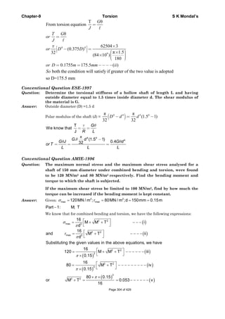
![Chapter-9 Torsion S K Mondal’s
( )
( )
[ ]3
Substituting this values in equation iii ,we get
16
120 M 0.053
0.150
M 0.0265MNm
π
= +
×
∴ =
( )
( )
2 2
Substituting for M in equation v ,we have
0.0265 T 0.053
or T 0.0459MNm
+ =
=
( )
2
maxPart II: [ 100MN / m ]
Increase in torque :
Bending moment M to be kept constant 0.0265MNm
τ =
=
∵
( )
( )
23
2 2
100 0.15
or 0.0265 T 0.004391
16
π⎡ ⎤× ×
⎢ ⎥+ = =
⎢ ⎥⎣ ⎦
T 0.0607 MNm
The increased torque 0.0607 0.0459 0.0148MNm
∴ =
∴ = − =
Conventional Question ESE-1996
Question: A solid shaft is to transmit 300 kW at 120 rpm. If the shear stress is not to
exceed 100 MPa, Find the diameter of the shaft, What percent saving in
weight would be obtained if this shaft were replaced by a hollow one whose
internal diameter equals 0.6 of the external diameter, the length, material
and maximum allowable shear stress being the same?
Answer: Given P= 300 kW, N = 120 rpm, τ =100 MPa, 0.6H Hd D=
Diameter of solid shaft, Ds:
We know that P =
2π
60 1000
NT
×
or 300 =
2π 120
or T=23873 Nm
60 1000
× ×
×
T
We know that
τ
=
T
J R
or, T=
.τ J
R
or, 23873 =
6 4π
100 10
32
2
× × s
s
D
D
or, Ds= 0.1067 m =106.7mm
Percentage saving in weight:
H sT T=
Page 305 of 429](https://image.slidesharecdn.com/strengthofmaterialsbyskmondal-130102103545-phpapp02-150924095946-lva1-app6891/85/Strengthofmaterialsbyskmondal-130102103545-phpapp02-305-320.jpg)

![Chapter-10 Thin Cylinder S K Mondal’s
3. General Formula
1 2
1 2
σ σ
+ =
p
r r t
Where 1σ =Meridional stress at A
2σ =Circumferential / Hoop's stress
P = Intensity of internal gas pressure/ fluid pressure
t = Thickness of pressure vessel.
4. Some cases:
• Cylindrical vessel
1 2=
2 4 2
σ σ= = =
pr pD pr pD
t t t t
1 2,r r r⎡ ⎤→ ∞ =⎣ ⎦
1 2
max
2 4 8
σ σ
τ
−
= = =
pr pD
t t
• Spherical vessel
1 2
2 4
σ σ= = =
pr pD
t t
[r1 = r2 = r]
• Conical vessel
1 1
tan
[ ]
2 cos
py
r
t
α
σ
α
= → ∞ and 2
tan
cos
py
t
α
σ
α
=
Notes:
• Volume 'V' of the spherical shell,
3
V=
6
π
iD
1/3
6
π
⎛ ⎞
⇒ = ⎜ ⎟
⎝ ⎠
i
V
D
• Design of thin cylindrical shells is based on hoop's stress
5. Volumetric Strain (Dilation)
• Rectangular block,
0
x y z
V
V
Δ
=∈ +∈ +∈
• Cylindrical pressure vessel
∈1=Longitudinal strain = [ ]1 2
1 2
2
pr
E E Et
σ σ
μ μ− = −
2∈ =Circumferential strain = [ ]2 1
1 2
2
σ σ
μ μ− = −
pr
E E Et
Volumetric Strain, 1 22 [5 4μ] [5 4μ]
2 4
Δ
=∈ + ∈ = − = −
o
V pr pD
V Et Et
i.e. ( ) ( ) ( )1 2, 2vVolumetric strain longitudinal strain circumferential strain∈ = ∈ + × ∈
• Spherical vessels
1 2 [1 ]
2
pr
Et
μ∈=∈ =∈ = −
α
α α
α
1σ
2σ2σ
Page 309 of 429](https://image.slidesharecdn.com/strengthofmaterialsbyskmondal-130102103545-phpapp02-150924095946-lva1-app6891/85/Strengthofmaterialsbyskmondal-130102103545-phpapp02-309-320.jpg)
![Chapter-10 Thin Cylinder S K Mondal’s
0
3
3 [1 ]
2
V pr
V Et
μ
Δ
= ∈= −
6. Thin cylindrical shell with hemispherical end
Condition for no distortion at the junction of cylindrical and hemispherical portion
2
1
1
2
t
t
μ
μ
−
=
−
Where, t1= wall thickness of cylindrical portion
t2 = wall thickness of hemispherical portion
7. Alternative method
Consider the equilibrium of forces in the z-direction acting on the part
cylinder shown in figure.
Force due to internal pressure p acting on area π D2/4 = p. π D2/4
Force due to longitudinal stress sL acting on area π Dt = 1σ π Dt
Equating: p. π D2/4 = 1σ π Dt
or 1
4 2
pd pr
t t
σ = =
Now consider the equilibrium of forces in the x-direction acting on the
sectioned cylinder shown in figure. It is assumed that the
circumferential stress 2σ is constant through the thickness of the
cylinder.
Force due to internal pressure p acting on area Dz = pDz
Force due to circumferential stress 2σ acting on area 2tz = 2σ 2tz
Equating: pDz = 2σ 2tz
or 2
2
pD pr
t t
σ = =
Page 310 of 429](https://image.slidesharecdn.com/strengthofmaterialsbyskmondal-130102103545-phpapp02-150924095946-lva1-app6891/85/Strengthofmaterialsbyskmondal-130102103545-phpapp02-310-320.jpg)
![Chapter-10 Thin Cylinder S K Mondal’s
OBJECTIVE QUESTIONS (GATE, IES, IAS)
Previous 20-Years GATE Questions
Longitudinal stress
GATE-1. The maximum principal strain in a thin cylindrical tank, having a radius of 25
cm and wall thickness of 5 mm when subjected to an internal pressure of 1MPa,
is (taking Young's modulus as 200 GPa and Poisson's ratio as 0.2) [GATE-1998]
(a) 2.25 × 10⁻⁴ (b) 2.25 (c) 2.25 × 10⁻⁶ (d) 22.5
GATE-1. Ans. (a) Circumferential or Hoop stress ( )c
pr 1 250
50MPa
t 5
σ
×
= = =
Longitudinal stress ( )l
pr
25MPa
2t
σ = =
6 6
4c l
c 9 9
50 10 25 10
e 0.2 2.25 10
E E 200 10 200 10
σ σ
μ −× ×
= − = − × = ×
× ×
Maximum shear stress
GATE-2. A thin walled cylindrical vessel of well thickness, t and diameter d is fitted
with gas to a gauge pressure of p. The maximum shear stress on the vessel wall
will then be: [GATE-1999]
(a) (b) (c) (d)
2 4 8
pd pd pd pd
t t t t
GATE-2. Ans. (d) c l
c l
pd pd pd
, , Maximum shear stress
2t 4t 2 8t
σ σ
σ σ
−
= = = =
Change in dimensions of a thin cylindrical shell due to an internal
pressure
Statement for Linked Answers and Questions 3 and 4
A cylindrical container of radius R = 1 m, wall
thickness 1 mm is filled with water up to a depth
of 2 m and suspended along its upper rim. The
density of water is 1000 kg/m3 and acceleration
due to gravity is 10 m/s2. The self-weight of the
cylinder is negligible. The formula for hoop
stress in a thin-walled cylinder can be used at all
points along the height of the cylindrical
container.
[GATE-2008]
GATE-3. The axial and circumferential stress ( ), ca σσ experienced by the cylinder wall
at mid-depth (1 m as shown) are
(a) (10,10) MPa (b) (5,10) MPa (c) (10,5) MPa (d) (5,5)MPa
GATE-3. Ans. (a) Pressure (P) = h ρ g = 1×1000×10 = 10 kPa
Axial Stress ( aσ ) LRgRta
2
2 πρπσ ×=×⇒
or
ρ
σ −
× × ×
= = =
× 3
1000 10 1 1
10MPa
1 10
a
gRL
t
Circumferential Stress( cσ )= −
×
= =
× 3
10 1
10MPa
1 10
PR
t
Page 311 of 429](https://image.slidesharecdn.com/strengthofmaterialsbyskmondal-130102103545-phpapp02-150924095946-lva1-app6891/85/Strengthofmaterialsbyskmondal-130102103545-phpapp02-311-320.jpg)
![Chapter-10 Thin Cylinder S K Mondal’s
GATE-4. If the Young's modulus and Poisson's ratio of the container material are 100
GPa and 0.3, respectively, the axial strain in the cylinder wall at mid-depth is:
(a) 2 × 10⁻⁵ (b) 6 × 10⁻⁵ (c) 7 × 10⁻⁵ (d) 1.2 × 10⁻⁵
GATE-4. Ans. (c)
5
33
107
10100
10
3.0
10100
10 −
−−
×=
×
×−
×
=−=
EE
ca
a
σ
μ
σ
ε
Previous 20-Years IES Questions
Circumferential or hoop stress
IES-1. Match List-I with List-II and select the correct answer: [IES-2002]
List-I List-II
(2-D Stress system loading) (Ratio of principal stresses)
A. Thin cylinder under internal pressure 1. 3.0
B. Thin sphere under internal pressure 2. 1.0
C. Shaft subjected to torsion 3. –1.0
4. 2.0
Codes: A B C A B C
(a) 4 2 3 (b) 1 3 2
(c) 4 3 2 (d) 1 2 3
IES-1. Ans. (a)
IES-2. A thin cylinder of radius r and thickness t when subjected to an internal
hydrostatic pressure P causes a radial displacement u, then the tangential
strain caused is: [IES-2002]
(a)
du
dr
(b)
1
.
du
r dr
(c)
u
r
(d)
2u
r
IES-2. Ans. (c)
IES-3. A thin cylindrical shell is subjected to internal pressure p. The Poisson's ratio
of the material of the shell is 0.3. Due to internal pressure, the shell is subjected
to circumferential strain and axial strain. The ratio of circumferential strain to
axial strain is: [IES-2001]
(a) 0.425 (b) 2.25 (c) 0.225 (d) 4.25
IES-3. Ans. (d) Circumferential strain, ( )c l
c
pr
e 2
E E 2Et
σ σ
μ μ= − = −
Longitudinal strain, ( )cl
l
pr
e 1 2
E E 2Et
σσ
μ μ= − = −
IES-4. A thin cylindrical shell of diameter d, length ‘l’ and thickness t is subjected to
an internal pressure p. What is the ratio of longitudinal strain to hoop strain in
terms of Poisson's ratio (1/m)? [IES-2004]
(a)
2
2 1
m
m
−
+
(b)
2
2 1
m
m
−
−
(c)
2 1
2
m
m
−
−
(d)
2 2
1
m
m
+
−
IES-4. Ans. (b) ( )l
Pr
longitudinal stress
2t
σ =
Page 312 of 429](https://image.slidesharecdn.com/strengthofmaterialsbyskmondal-130102103545-phpapp02-150924095946-lva1-app6891/85/Strengthofmaterialsbyskmondal-130102103545-phpapp02-312-320.jpg)
![Chapter-10 Thin Cylinder S K Mondal’s
( )c
cl
l
c lc
Pr
hoop stress
t
1 1 1
m 2E m E 2 m
11 2m 1
1
2mE m E
σ
σσ
σ σ
=
− −
∈ −
∴ = = =
∈ −
−−
IES-5. When a thin cylinder of diameter 'd' and thickness 't' is pressurized with an
internal pressure of 'p', (1/m = μ is the Poisson's ratio and E is the modulus of
elasticity), then [IES-1998]
(a) The circumferential strain will be equal to
1 1
2 2
pd
tE m
⎛ ⎞
−⎜ ⎟
⎝ ⎠
(b) The longitudinal strain will be equal to
1
1
2 2
pd
tE m
⎛ ⎞
−⎜ ⎟
⎝ ⎠
(c) The longitudinal stress will be equal to
2
pd
t
(d) The ratio of the longitudinal strain to circumferential strain will be equal to
2
2 1
m
m
−
−
IES-5. Ans. (d) Ratio of longitudinal strain to circumferential strain
=
{ }
{ }
1 1
2
2
1 1 2 1
2
l c l l
c l l l
mm m
m
m m
σ σ σ σ
σ σ σ σ
⎛ ⎞ ⎛ ⎞
− −⎜ ⎟ ⎜ ⎟ −⎝ ⎠ ⎝ ⎠= =
−⎛ ⎞ ⎛ ⎞
− −⎜ ⎟ ⎜ ⎟
⎝ ⎠ ⎝ ⎠
Circumferential strain, ( )c l
c
pr
e 2
E E 2Et
σ σ
μ μ= − = −
Longitudinal strain, ( )cl
l
pr
e 1 2
E E 2Et
σσ
μ μ= − = −
IES-6. A thin cylinder contains fluid at a pressure of 500 N/m2, the internal diameter
of the shell is 0.6 m and the tensile stress in the material is to be limited to 9000
N/m2. The shell must have a minimum wall thickness of nearly [IES-2000]
(a) 9 mm (b) 11 mm (c) 17 mm (d) 21 mm
IES-6. Ans. (c)
IES-7. A thin cylinder with closed
lids is subjected to internal
pressure and supported at
the ends as shown in figure.
The state of stress at point
X is as represented in
[IES-1999]
Page 313 of 429](https://image.slidesharecdn.com/strengthofmaterialsbyskmondal-130102103545-phpapp02-150924095946-lva1-app6891/85/Strengthofmaterialsbyskmondal-130102103545-phpapp02-313-320.jpg)
![Chapter-10 Thin Cylinder S K Mondal’s
IES-7. Ans. (a) Point 'X' is subjected to circumferential and longitudinal stress, i.e. tension on all
faces, but there is no shear stress because vessel is supported freely outside.
IES-8. A thin cylinder with both ends closed is subjected to internal pressure p. The
longitudinal stress at the surface has been calculated as σo. Maximum shear
stress at the surface will be equal to: [IES-1999]
( ) ( ) ( ) ( )a 2 b 1.5 c d 0.5o o o oσ σ σ σ
IES-8. Ans. (d)
2
Longitudinal stress hoop stress 2 Max. shear stress
2 2
o o o
o oand
σ σ σ
σ σ
−
= = = =
IES-9. A metal pipe of 1m diameter contains a fluid having a pressure of 10 kgf/cm2. lf
the permissible tensile stress in the metal is 200 kgf/cm2, then the thickness of
the metal required for making the pipe would be: [IES-1993]
(a) 5 mm (b) 10 mm (c) 20 mm (d) 25 mm
IES-9. Ans. (d)
10 100 1000
Hoop stress 200 2.5
2 2 400
pd
or or t cm
t t
×
= = = =
×
IES-10. Circumferential stress in a cylindrical steel boiler shell under internal
pressure is 80 MPa. Young's modulus of elasticity and Poisson's ratio are
respectively 2 × 10⁵ MPa and 0.28. The magnitude of circumferential strain in
the boiler shell will be: [IES-1999]
(a) 3.44 × 10⁻⁴ (b) 3.84 × 10⁻⁴ (c) 4 × 10⁻⁴ (d) 4.56 ×10 –4
IES-10. Ans. (a) Circumferential strain = ( )1 2
1
E
σ μσ−
[ ]
1 2
6 4
5 6
Since circumferential stress 80 MPa and longitudinal stress 40 MPa
1
Circumferential strain 80 0.28 40 10 3.44 x10
2 10 10
σ σ
−
= =
∴ = − × × =
× ×
IES-11. A penstock pipe of 10m diameter carries water under a pressure head of 100 m.
If the wall thickness is 9 mm, what is the tensile stress in the pipe wall in MPa?
[IES-2009]
(a) 2725 (b) 545·0 (c) 272·5 (d) 1090
IES-11. Ans. (b) Tensile stress in the pipe wall = Circumferential stress in pipe wall =
Pd
2t
2
6 2 2
3
Where, P gH 980000N / m
980000 10
Tensile stress 544.44 10 N / m 544.44MN / m 544.44MPa
2 9 10−
= ρ =
×
∴ = = × = =
× ×
IES-12. A water main of 1 m diameter contains water at a pressure head of 100 metres.
The permissible tensile stress in the material of the water main is 25 MPa.
What is the minimum thickness of the water main? (Take g = 10 m/
2
s ).
[IES-2009]
(a) 10 mm (b) 20mm (c) 50 mm (d) 60 mm
IES-12. Ans. (b) Pressure in the main
6 2
gh 1000 10 1000 = 10 N / mm 1000 KPa= ρ = × × =
( )( )
c
6
6
c
Pd
Hoop stress
2t
10 1Pd 1
t m 20 mm
2 502 25 10
= σ =
∴ = = = =
σ × ×
Page 314 of 429](https://image.slidesharecdn.com/strengthofmaterialsbyskmondal-130102103545-phpapp02-150924095946-lva1-app6891/85/Strengthofmaterialsbyskmondal-130102103545-phpapp02-314-320.jpg)
![Chapter-10 Thin Cylinder S K Mondal’s
Longitudinal stress
IES-13. Hoop stress and longitudinal stress in a boiler shell under internal pressure
are 100 MN/m2 and 50 MN/m2 respectively. Young's modulus of elasticity and
Poisson's ratio of the shell material are 200 GN/m2 and 0.3 respectively. The
hoop strain in boiler shell is: [IES-1995]
(a) 0.425
3
10−
× (b) 0.5
3
10−
× (c) 0.585
3
10−
× (d) 0.75
3
10−
×
IES-13. Ans. (a) ( ) [ ] 31 1
Hoopstrain = 100 0.3 50 0.425 10
200 1000
h l
E
σ μσ −
− = − × = ×
×
IES-14. In strain gauge dynamometers, the use of how many active gauge makes the
dynamometer more effective? [IES 2007]
(a) Four (b) Three (c) Two (d) One
IES-14. Ans. (b)
Volumetric strain
IES-15. Circumferential and longitudinal strains in a cylindrical boiler under internal
steam pressure are 1ε and 2ε respectively. Change in volume of the boiler
cylinder per unit volume will be: [IES-1993; IAS 2003]
2 2
1 2 1 2 1 2 1 2(a) 2 (b) (c)2 (d)ε ε ε ε ε ε ε ε+ +
IES-15. Ans. (c) Volumetric stream = 2 × circumferential strain + longitudinal strain
IES-16. The volumetric strain in case of a thin cylindrical shell of diameter d, thickness
t, subjected to internal pressure p is: [IES-2003; IAS 1997]
(a) ( ). 3 2
2
pd
tE
μ− (b) ( ). 4 3
3
pd
tE
μ− (c) ( ). 5 4
4
pd
tE
μ− (d) ( ). 4 5
4
pd
tE
μ−
(Where E = Modulus of elasticity, μ = Poisson's ratio for the shell material)
IES-16. Ans. (c) Remember it.
Spherical Vessel
IES-17. For the same internal diameter, wall thickness, material and internal pressure,
the ratio of maximum stress, induced in a thin cylindrical and in a thin
spherical pressure vessel will be: [IES-2001]
(a) 2 (b) 1/2 (c) 4 (d) 1/4
IES-17. Ans. (a)
IES-18. From design point of view, spherical pressure vessels are preferred over
cylindrical pressure vessels because they [IES-1997]
(a) Are cost effective in fabrication
(b) Have uniform higher circumferential stress
(c) Uniform lower circumferential stress
(d) Have a larger volume for the same quantity of material used
IES-18. Ans. (d)
Previous 20-Years IAS Questions
Circumferential or hoop stress
IAS-1. The ratio of circumferential stress to longitudinal stress in a thin cylinder
subjected to internal hydrostatic pressure is: [IAS 1994]
(a) 1/2 (b) 1 (c) 2 (d) 4
IAS-1. Ans. (c)
Page 315 of 429](https://image.slidesharecdn.com/strengthofmaterialsbyskmondal-130102103545-phpapp02-150924095946-lva1-app6891/85/Strengthofmaterialsbyskmondal-130102103545-phpapp02-315-320.jpg)
![Chapter-10 Thin Cylinder S K Mondal’s
IAS-2. A thin walled water pipe carries water under a pressure of 2 N/mm2 and
discharges water into a tank. Diameter of the pipe is 25 mm and thickness is
2·5 mm. What is the longitudinal stress induced in the pipe? [IAS-2007]
(a) 0 (b) 2 N/mm2 (c) 5 N/mm2 (d) 10 N/mm2
IAS-2. Ans. (c)
2Pr 2 12.5
5N/mm
2 2 2.5t
σ
×
= = =
×
IAS-3. A thin cylindrical shell of mean diameter 750 mm and wall thickness 10 mm has
its ends rigidly closed by flat steel plates. The shell is subjected to internal
fluid pressure of 10 N/mm2 and an axial external pressure P1. If the
longitudinal stress in the shell is to be zero, what should be the approximate
value of P1? [IAS-2007]
(a) 8 N/mm2 (b) 9 N/mm2 (c) 10 N/mm2 (d) 12 N/mm2
IAS-3. Ans. (c) Tensile longitudinal stress due to internal fluid pressure (δ 1) t =
2
750
10
4
750 10
π
π
⎛ ⎞×
×⎜ ⎟
⎝ ⎠
× ×
tensile. Compressive longitudinal stress due to external pressure p1 ( δ l)c =
2
1
750
4
750 10
P
π
π
⎛ ⎞×
×⎜ ⎟
⎝ ⎠
× ×
compressive. For zero longitudinal stress (δ l) t = (δ l)c.
IAS-4. Assertion (A): A thin cylindrical shell is subjected to internal fluid pressure
that induces a 2-D stress state in the material along the longitudinal and
circumferential directions. [IAS-2000]
Reason(R): The circumferential stress in the thin cylindrical shell is two times
the magnitude of longitudinal stress.
(a) Both A and R are individually true and R is the correct explanation of A
(b) Both A and R are individually true but R is NOT the correct explanation of A
(c) A is true but R is false
(d) A is false but R is true
IAS-4. Ans. (b) For thin cell
Pr Pr
2
c l
t t
σ σ= =
IAS-5. Match List-I (Terms used in thin cylinder stress analysis) with List-II
(Mathematical expressions) and select the correct answer using the codes
given below the lists: [IAS-1998]
List-I List-II
A. Hoop stress 1. pd/4t
B. Maximum shear stress 2. pd/2t
C. Longitudinal stress 3. pd/2σ
D. Cylinder thickness 4. pd/8t
Codes: A B C D A B C D
(a) 2 3 1 4 (b) 2 3 4 1
(c) 2 4 3 1 (d) 2 4 1 3
IAS-5. Ans. (d)
Longitudinal stress
IAS-6. Assertion (A): For a thin cylinder under internal pressure, At least three strain
gauges is needed to know the stress state completely at any point on the shell.Page 316 of 429](https://image.slidesharecdn.com/strengthofmaterialsbyskmondal-130102103545-phpapp02-150924095946-lva1-app6891/85/Strengthofmaterialsbyskmondal-130102103545-phpapp02-316-320.jpg)
![Chapter-10 Thin Cylinder S K Mondal’s
Reason (R): If the principal stresses directions are not know, the minimum
number of strain gauges needed is three in a biaxial field. [IAS-2001]
(a) Both A and R are individually true and R is the correct explanation of A
(b) Both A and R are individually true but R is NOT the correct explanation of A
(c) A is true but R is false
(d) A is false but R is true
IAS-6. Ans. (d) For thin cylinder, variation of radial strain is zero. So only circumferential and
longitudinal strain has to measurer so only two strain gauges are needed.
Maximum shear stress
IAS-7. The maximum shear stress is induced in a thin-walled cylindrical shell having
an internal diameter 'D' and thickness’t’ when subject to an internal pressure
'p' is equal to: [IAS-1996]
(a) pD/t (b) pD/2t (c) pD/4t (d) pD/8t
IAS-7. Ans. (d) c l
c l max
PD PD PD
Hoop stress( ) and Longitudinalstress( )
2t 4t 2 8t
σ σ
σ σ τ
−
= = ∴ = =
Volumetric strain
IAS-8. Circumferential and longitudinal strains in a cylindrical boiler under internal
steam pressure are 1ε and 2ε respectively. Change in volume of the boiler
cylinder per unit volume will be: [IES-1993; IAS 2003]
2 2
1 2 1 2 1 2 1 2(a) 2 (b) (c)2 (d)ε ε ε ε ε ε ε ε+ +
IAS-8. Ans. (c) Volumetric stream = 2 x circumferential strain + longitudinal strain.
IAS-9. The volumetric strain in case of a thin cylindrical shell of diameter d, thickness
t, subjected to internal pressure p is: [IES-2003; IAS 1997]
(a) ( ). 3 2
2
pd
tE
μ− (b) ( ). 4 3
3
pd
tE
μ− (c) ( ). 5 4
4
pd
tE
μ− (d) ( ). 4 5
4
pd
tE
μ−
(Where E = Modulus of elasticity, μ = Poisson's ratio for the shell material)
IAS-9. Ans. (c) Remember it.
IAS-10. A thin cylinder of diameter ‘d’ and thickness 't' is subjected to an internal
pressure 'p' the change in diameter is (where E is the modulus of elasticity and
μ is the Poisson's ratio) [IAS-1998]
(a)
2
(2 )
4
pd
tE
μ− (b)
2
(1 )
2
pd
tE
μ+ (c)
2
(2 )
pd
tE
μ+ (d)
2
(2 )
4
pd
tE
μ+
IAS-10. Ans. (a)
IAS-11. The percentage change in volume of a thin cylinder under internal pressure
having hoop stress = 200 MPa, E = 200 GPa and Poisson's ratio = 0·25 is:
[IAS-2002]
(a) 0.40 (b) 0·30 (c) 0·25 (d) 0·20
IAS-11. Ans. (d) ( ) 6Pr
Hoop stress 200 10t aP
t
σ = = ×
Page 317 of 429](https://image.slidesharecdn.com/strengthofmaterialsbyskmondal-130102103545-phpapp02-150924095946-lva1-app6891/85/Strengthofmaterialsbyskmondal-130102103545-phpapp02-317-320.jpg)
![Chapter-10 Thin Cylinder S K Mondal’s
( ) ( )
( )
6
9
Pr
Volumetric strain ( ) 5 4 5 4
2 2
200 10 2
5 4 0.25
2 200 10 1000
t
ve
Et E
σ
μ μ= − = −
×
= − × =
× ×
IAS-12. A round bar of length l, elastic modulus E and Poisson's ratio μ is subjected to
an axial pull 'P'. What would be the change in volume of the bar? [IAS-2007]
(a)
(1 2 )
Pl
Eμ−
(b)
(1 2 )Pl
E
μ−
(c)
Pl
E
μ
(d)
Pl
Eμ
IAS-12. Ans. (b)
, 0 and 0
or ,
x y z
x x
x y
P
A
E E
σ σ σ
σ σ
ε ε μ
= = =
= = −
( ) ( )
( )
and
or 1 2 1 2
. 1 2
x
z
x
v x y z
v v
E
P
E AE
Pl
V V Al
E
σ
ε μ
σ
ε ε ε ε μ μ
δ ε ε μ
= −
= + + = − = −
= × = = −
IAS-13. If a block of material of length 25 cm. breadth 10 cm and height 5 cm undergoes
a volumetric strain of 1/5000, then change in volume will be: [IAS-2000]
(a) 0.50 cm3 (b) 0.25 cm3 (c) 0.20 cm3 (d) 0.75 cm3
IAS-13. Ans. (b)
3
Volumechange(δV)
Volumetricstrain( )
Initialvolume(V)
1
or ( ) 25 10 5 0.25
5000
v
vV V cm
ε
δ ε
=
= × = × × × =
Page 318 of 429](https://image.slidesharecdn.com/strengthofmaterialsbyskmondal-130102103545-phpapp02-150924095946-lva1-app6891/85/Strengthofmaterialsbyskmondal-130102103545-phpapp02-318-320.jpg)
![Chapter-10 Thin Cylinder S K Mondal’s
Hoop or circumferential stress ( )σ
2
c
Pd
t
=
And longitudinal stress( )σ =
4
Pd
t
Therefore σ 2σc =
Conventional Question IES-2009
Q. A cylindrical shell has the following dimensions:
Length = 3 m
Inside diameter = 1 m
Thickness of metal = 10 mm
Internal pressure = 1.5 MPa
Calculate the change in dimensions of the shell and the maximum intensity of
shear stress induced. Take E = 200 GPa and Poisson’s ratio ν = 0.3 [15-Marks]
Ans. We can consider this as a thin cylinder.
Hoop stresses,
Longitudinal stresses,
Shear stress =
Hence from the given data
6
8
1 3
1.5 10 1
0.75 10
2 10 10−
× ×
σ = = ×
× ×
6
6
2 3
1.5 10 1
37.5 10
4 10 10
37.5 MPa
−
× ×
σ = = ×
× ×
=
( )
( )
( )
( )
1
1 1 2
6
3 9
6
9
3
3
Hoop strain
1
v
E
Pd
2 v
4tE
1.5 10 1
2 0.3
4 10 10 200 10
37.5 10
2 0.3
200 10
0.31875 10
d
0.3187 10
d
−
−
−
ε
ε = σ − σ
= −
× ×
= −
× × × ×
×
= −
×
= ×
Δ
= ×
3
change in diameter,
d = 1 × 0.31875 × 10 m
= 0.31875 mm
−
∴
Δ
1
pd
2t
σ =
2
pd
4t
σ =
1 2
2
σ − σ
pd
8t
=
75 MPa=
Page 320 of 429](https://image.slidesharecdn.com/strengthofmaterialsbyskmondal-130102103545-phpapp02-150924095946-lva1-app6891/85/Strengthofmaterialsbyskmondal-130102103545-phpapp02-320-320.jpg)
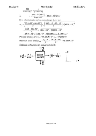
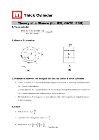
![Chapter-11 Thick Cylinder S K Mondal’s
5. Stress
• Axial stress,
2
2 2
0
σ =
−
i i
z
i
p r
r r
• Radial stress, 2r
B
A
r
σ = −
• Circumferential /Tangential stress, 2t
B
A
r
σ = +
[Note: Radial stress always compressive so its magnitude always –ive. But in some books they
assume that compressive radial stress is positive and they use, 2
σ = −r
B
A
r
]
6. Boundary Conditions
At = ir r , σ = −r ip
At = or r r opσ = −
7.
2 2
2 2
−
=
−
i i o o
o i
p r p r
A
r r
and
2 2
2 2
( )
( )
= −
−
i o
i o
o i
r r
B p p
r r
8. Cylinders with internal pressure (pi) i.e. 0op =
•
2
2 2
0
σ =
−
i i
z
i
p r
r r
•
2 2
0
2 2 2
0
1σ
⎡ ⎤
= − −⎢ ⎥
− ⎣ ⎦
i i
r
i
p r r
r r r
[ -ive means compressive stress]
•
2 2
0
2 2 2
0
1σ
⎡ ⎤
= + +⎢ ⎥
− ⎣ ⎦
i i
t
i
p r r
r r r
(a) At the inner surface of the cylinder
r
2 2
t 2 2
2
max 2 2
( )
( )
( )
( )
( ) .
i
i
i o i
o i
o
i
o i
i r r
ii p
p r r
iii
r r
r
iv p
r r
σ
σ
τ
=
= −
+
= +
−
=
−
(b) At the outer surface of the cylinder
Page 324 of 429](https://image.slidesharecdn.com/strengthofmaterialsbyskmondal-130102103545-phpapp02-150924095946-lva1-app6891/85/Strengthofmaterialsbyskmondal-130102103545-phpapp02-324-320.jpg)
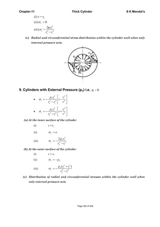
![Chapter-11 Thick Cylinder S K Mondal’s
10. Lame's Equation [for Brittle Material, open or closed end]
There is a no of equations for the design of thick cylinders. The choice of equation depends upon two
parameters.
• Cylinder Material (Whether brittle or ductile)
• Condition of Cylinder ends (open or closed)
When the material of the cylinder is brittle, such as cast iron or cast steel, Lame's Equation is used to
determine the wall thickness. Condition of cylinder ends may open or closed.
It is based on maximum principal stress theory of failure.
There principal stresses at the inner surface of the cylinder are as follows: (i) (ii) & (iii)
2 2
0
t 2 2
0
2
z 2 2
( )
( )
( )
( )
σ
σ
σ
= −
+
= +
−
= +
−
r i
i i
i
i i
o i
i p
p r r
ii
r r
p r
iii
r r
• tσ σ σ> >z r
• t is the criterion of designσ o
i
σ
σ
+
=
−
t i
t i
r p
r p
• For o ir r t= +
• t 1
σ
σ
⎡ ⎤+
= × −⎢ ⎥
−⎢ ⎥⎣ ⎦
t i
i
t i
p
r
p
( ' )Lame s Equation
• t
σ
σ = ult
fos
11. Clavarino's Equation [for cylinders with closed end & made of ductile material]
When the material of a cylinder is ductile, such as mild steel or alloy steel, maximum strain theory
of failure is used (St. Venant's theory) is used.
Three principal stresses at the inner surface of the cylinder are as follows (i) (ii) & (iii)
Page 326 of 429](https://image.slidesharecdn.com/strengthofmaterialsbyskmondal-130102103545-phpapp02-150924095946-lva1-app6891/85/Strengthofmaterialsbyskmondal-130102103545-phpapp02-326-320.jpg)
![Chapter-11 Thick Cylinder S K Mondal’s
r
2 2
2 2
2
2 2
( )
( )
( )
( )
( )
( )
σ
σ
σ
= −
+
= +
−
= +
−
i
i o i
t
o i
i i
z
o i
i p
p r r
ii
r r
p r
iii
r r
• ( )1
σ σ σ⎡ ⎤∈ = − +⎣ ⎦t t r z
E
•
/σσ
∈ = = yld
t
fos
E E
• Or
yld
( ). Where =
fos
σ
σ σ μ σ σ σ= − +t r z
• σ is the criterion of design
(1 2 )
(1 )
σ μ
σ μ
+ −
=
− +
o i
i i
r p
r p
• For ro = ri + t
(1 2 )
1
(1 )
σ μ
σ μ
⎡ ⎤+ −
= −⎢ ⎥
− +⎣ ⎦
i
i
i
p
t r
p
( )Clavarion's Equation
12. Birne's Equation [for cylinders with open end & made of ductile material]
When the material of a cylinder is ductile, such as mild steel or alloy steel, maximum strain theory
of failure is used (St. Venant's theory) is used.
Three principal stresses at the inner surface of the cylinder are as follows (i) (ii) & (iii)
r
2 2
2 2
( )
( )
( )
( )
( ) 0
σ
σ
σ
= −
+
= +
−
=
i
i o i
t
o i
z
i p
p r r
ii
r r
iii
•
yld
where =
fos
σ
σ σ μσ σ= −t r
• σ is the criterion of design
(1 )
(1 )
σ μ
σ μ
+ −
=
− +
o i
i i
r p
r p
• For ro = ri + t
(1 )
1
(1 )
σ μ
σ μ
⎡ ⎤+ −
= × −⎢ ⎥
− +⎣ ⎦
i
i
i
p
t r
p
(Birnie's Equation)
13. Barlow’s equation: [for high pressure gas pipe brittle or ductile material]
Page 327 of 429](https://image.slidesharecdn.com/strengthofmaterialsbyskmondal-130102103545-phpapp02-150924095946-lva1-app6891/85/Strengthofmaterialsbyskmondal-130102103545-phpapp02-327-320.jpg)
![Chapter-11 Thick Cylinder S K Mondal’s
i
o
t
p
t r
σ
= [GAIL exam 2004]
Where
y
t for ductile material
fos
σ
σ =
ult
for brittlematerial
fos
σ
=
14. Compound Cylinder (A cylinder & A Jacket)
• When two cylindrical parts are assembled by shrinking or press-fitting, a contact pressure is
created between the two parts. If the radii of the inner cylinder are a and c and that of the
outer cylinder are (c- δ ) and b, δ being the radial interference the contact pressure is given
by:
( )2 2 2 2
2 2 2
( )
2 ( )
b c c aE
P
c c b a
δ
⎡ ⎤− −⎢ ⎥= ⎢ ⎥
−⎢ ⎥⎣ ⎦
Where E is the Young's modulus of the material
• The inner diameter of the jacket is slightly smaller than the outer diameter of cylinder
• When the jacket is heated, it expands sufficiently to move over the cylinder
• As the jacket cools, it tends to contract onto the inner cylinder, which induces residual
compressive stress.
• There is a shrinkage pressure 'P' between the cylinder and the jacket.
• The pressure 'P' tends to contract the cylinder and expand the jacket
• The shrinkage pressure 'P' can be evaluated from the above equation for a given amount of
interference δ
• The resultant stresses in a compound cylinder are found by supervision losing the 2- stresses
stresses due to shrink fit
stresses due to internal pressure
Derivation:
j
δ
δ
δ δ δ
j
c
c
Due to interference let us assume increase in inner diameter
of jacket and decrease in outer diameter of cylinder.
so = + i.e. without sign.
=
=
Page 328 of 429](https://image.slidesharecdn.com/strengthofmaterialsbyskmondal-130102103545-phpapp02-150924095946-lva1-app6891/85/Strengthofmaterialsbyskmondal-130102103545-phpapp02-328-320.jpg)
![Chapter-11 Thick Cylinder S K Mondal’s
[ ]
( )
( )
j
µ
δ
σ µσ
t
2 2 2 2
2 2 2 2
r
Now tangential strain
1
=
σ =circumferential stress
cP p(b +c )
= ( ) +
E b -c
σ =-p radialstress
j j
t r
c
c
E
b c
i
b c
⎡ ⎤=∈ ∈ =⎢ ⎥⎣ ⎦
−
⎡ ⎤
⎢ ⎥
⎢ ⎥
⎡ ⎤ ⎢ ⎥+⎢ ⎥ ⎢ ⎥+ −−−
⎢ ⎥ ⎢ ⎥−⎣ ⎦ ⎢ ⎥
⎢ ⎥
⎢ ⎥⎣ ⎦
[ ] ( )
µ
σ
δ σ µσ
σ
-
2 2
t 2 2
2 2
2 2
( )
1
And in similar way =
cP
=- ( ) Here -ivesignrepresentscontraction
E
c c t r
r
p c a
c ac c
E
p
c a
ii
c a
⎡ ⎤+⎢ ⎥= −
⎢ ⎥−=∈ − ⎢ ⎥
⎢ ⎥
= −⎢ ⎥⎣ ⎦
⎡ ⎤+⎢ ⎥ −−−
⎢ ⎥−⎣ ⎦
δ
δ δ δ
2 2 2 2 2 2 2
2 2 2 2 2 2 2
Adding ( ) & ( )
2 ( ) ( )( )
or
( )( ) 2 ( )
j c
i ii
Pc c b a E b c c a
P
E cb c c a c b a
⎡ ⎤ ⎡ ⎤− − −⎢ ⎥ ⎢ ⎥∴ = + = =
⎢ ⎥ ⎢ ⎥− − −⎣ ⎦ ⎣ ⎦
15. Autofrettage
Autofrettage is a process of pre-stressing the cylinder before using it in operation.
We know that when the cylinder is subjected to internal pressure, the circumferential stress at the
inner surface limits the pressure carrying capacity of the cylinder.
In autofrettage pre-stressing develops a residual compressive stresses at the inner surface. When
the cylinder is actually loaded in operation, the residual compressive stresses at the inner surface
begin to decrease, become zero and finally become tensile as the pressure is gradually increased.
Thus autofrettage increases the pressure carrying capacity of the cylinder.
16. Rotating Disc
The radial & circumferential (tangential) stresses in a rotating disc of uniform thickness are given
by
( )
2 22
2 2 20
0 2
3
8
ρω
σ μ
⎛ ⎞
= + + − −⎜ ⎟
⎝ ⎠
i
r i
R R
R R r
r
( )
2 22
2 2 20
0 2
1 3
3 .
8 3
ρω μ
σ μ
μ
⎛ ⎞+
= + + + −⎜ ⎟
+⎝ ⎠
i
t i
R R
R R r
r
Where Ri = Internal radius
Ro = External radius
ρ = Density of the disc material
ω = Angular speed
μ = Poisson's ratio.
Page 329 of 429](https://image.slidesharecdn.com/strengthofmaterialsbyskmondal-130102103545-phpapp02-150924095946-lva1-app6891/85/Strengthofmaterialsbyskmondal-130102103545-phpapp02-329-320.jpg)
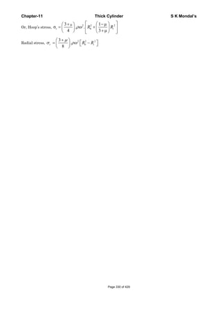
![Chapter-11 Thick Cylinder S K Mondal’s
OBJECTIVE QUESTIONS (GATE, IES, IAS)
Previous 20-Years GATE Questions
Lame's theory
GATE-1. A thick cylinder is subjected to an internal pressure of 60 MPa. If the hoop
stress on the outer surface is 150 MPa, then the hoop stress on the internal
surface is: [GATE-1996; IES-2001]
(a) 105 MPa (b) 180 MPa (c) 210 MPa (d) 135 MPa
GATE-1. Ans. (c) If internal pressure = pi; External pressure = zero
Circumferential or hoop stress (σc) =
22
oi i
2 2 2
o i
rpr
1
r r r
⎡ ⎤
+⎢ ⎥
− ⎣ ⎦
At i c op 60MPa, 150MPa and r rσ= = =
222 2 2
o oi i i
2 2 2 2 2 2 2
io i o o i o i
i
22
oi
c 2 2 2
o i i
r rr r r 150 5 9
150 60 1 120 or or
120 4 r 5r r r r r r r
at r r
rr 5 9
60 1 60 1 210 MPa
4 5r r r
σ
⎡ ⎤ ⎛ ⎞
∴ = + = = = =⎜ ⎟⎢ ⎥
− − − ⎝ ⎠⎣ ⎦
∴ =
⎡ ⎤ ⎛ ⎞
= + = × × + =⎢ ⎥ ⎜ ⎟
− ⎝ ⎠⎣ ⎦
Previous 20-Years IES Questions
Thick cylinder
IES-1. If a thick cylindrical shell is subjected to internal pressure, then hoop stress,
radial stress and longitudinal stress at a point in the thickness will be:
(a) Tensile, compressive and compressive respectively [IES-1999]
(b) All compressive
(c) All tensile
(d) Tensile, compressive and tensile respectively
IES-1. Ans. (d) Hoop stress – tensile, radial stress – compressive and longitudinal stress – tensile.
Radial and circumferential stress
distribution within the cylinder wall
when only internal pressure acts.
Distribution of radial and circumferential
stresses within the cylinder wall when only
external pressure acts.
IES-2. Where does the maximum hoop stress in a thick cylinder under external
pressure occur? [IES-2008]
(a) At the outer surface (b) At the inner surface
(c) At the mid-thickness (d) At the 2/3rd outer radius
Page 331 of 429](https://image.slidesharecdn.com/strengthofmaterialsbyskmondal-130102103545-phpapp02-150924095946-lva1-app6891/85/Strengthofmaterialsbyskmondal-130102103545-phpapp02-331-320.jpg)
![Chapter-11 Thick Cylinder S K Mondal’s
IES-2. Ans. (b)
Circumferential or hoop stress = tσ
IES-3. In a thick cylinder pressurized from inside, the hoop stress is maximum at
(a) The centre of the wall thickness (b) The outer radius [IES-1998]
(c) The inner radius (d) Both the inner and the outer radii
IES-3. Ans. (c)
IES-4. Where does the maximum hoop stress in a thick cylinder under external
pressure occur? [IES-2008]
(a) At the outer surface (b) At the inner surface
(c) At the mid-thickness (d) At the 2/3rd outer radius
IES-4. Ans. (a) Maximum hoop stress in thick cylinder under external pressure occur at the outer
surface.
IES-5. A thick-walled hollow cylinder having outside and inside radii of 90 mm and 40
mm respectively is subjected to an external pressure of 800 MN/m2. The
maximum circumferential stress in the cylinder will occur at a radius of
[IES-1998]
(a) 40 mm (b) 60 mm (c) 65 mm (d) 90 mm
IES-5. Ans. (a)
IES-6. In a thick cylinder, subjected to internal and external pressures, let r1 and r2 be
the internal and external radii respectively. Let u be the radial displacement of
a material element at radius r, 2 1r r r≥ ≥ . Identifying the cylinder axis as z axis,
the radial strain component rrε is: [IES-1996]
(a) u/r (b) /u θ (c) du/dr (d) du/dθ
IES-6. Ans. (c) The strains εr and εθ may be given by
Page 332 of 429](https://image.slidesharecdn.com/strengthofmaterialsbyskmondal-130102103545-phpapp02-150924095946-lva1-app6891/85/Strengthofmaterialsbyskmondal-130102103545-phpapp02-332-320.jpg)
![Chapter-11 Thick Cylinder S K Mondal’s
( )
θ
θ θ
ε σ σ σ
θ θ
ε σ σ
θ
∂
= = − =⎡ ⎤⎣ ⎦∂
+ Δ − Δ
= = = −⎡ ⎤⎣ ⎦Δ
1
since 0
1
r
r r z
r r
r
u
v
r E
r u r u
v
r r E
Representation of radial and
circumferential strain.
Lame's theory
IES-7. A thick cylinder is subjected to an internal pressure of 60 MPa. If the hoop
stress on the outer surface is 150 MPa, then the hoop stress on the internal
surface is: [GATE-1996; IES-2001]
(a) 105 MPa (b) 180 MPa (c) 210 MPa (d) 135 MPa
IES-7. Ans. (c) If internal pressure = pi; External pressure = zero
Circumferential or hoop stress (σc) =
22
oi i
2 2 2
o i
rpr
1
r r r
⎡ ⎤
+⎢ ⎥
− ⎣ ⎦
At i c op 60MPa, 150MPa and r rσ= = =
222 2 2
o oi i i
2 2 2 2 2 2 2
io i o o i o i
i
22
oi
c 2 2 2
o i i
r rr r r 150 5 9
150 60 1 120 or or
120 4 r 5r r r r r r r
at r r
rr 5 9
60 1 60 1 210 MPa
4 5r r r
σ
⎡ ⎤ ⎛ ⎞
∴ = + = = = =⎜ ⎟⎢ ⎥
− − − ⎝ ⎠⎣ ⎦
∴ =
⎡ ⎤ ⎛ ⎞
= + = × × + =⎢ ⎥ ⎜ ⎟
− ⎝ ⎠⎣ ⎦
IES-8. A hollow pressure vessel is subject to internal pressure. [IES-2005]
Consider the following statements:
1. Radial stress at inner radius is always zero.
2. Radial stress at outer radius is always zero.
3. The tangential stress is always higher than other stresses.
4. The tangential stress is always lower than other stresses.
Which of the statements given above are correct?
(a) 1 and 3 (b) 1 and 4 (c) 2 and 3 (d) 2 and 4
IES-8. Ans. (c)
IES-9. A thick open ended cylinder as shown in the
figure is made of a material with permissible
normal and shear stresses 200 MPa and 100 MPa
respectively. The ratio of permissible pressure
based on the normal and shear stress is:
[di = 10 cm; do = 20 cm]
(a) 9/5 (b) 8/5
(c) 7/5 (d) 4/5
[IES-2002]
IES-9. Ans. (b)
Longitudinal and shear stress
IES-10. A thick cylinder of internal radius and external radius a and b is subjected to
internal pressure p as well as external pressure p. Which one of the following
statements is correct? [IES-2004]
The magnitude of circumferential stress developed is:
(a) Maximum at radius r = a (b) Maximum at radius r = b
Page 333 of 429](https://image.slidesharecdn.com/strengthofmaterialsbyskmondal-130102103545-phpapp02-150924095946-lva1-app6891/85/Strengthofmaterialsbyskmondal-130102103545-phpapp02-333-320.jpg)
![Chapter-11 Thick Cylinder S K Mondal’s
(c) Maximum at radius r = ab (d) Constant
IES-10. Ans. (d)
( )
2 2 2 2
i i o o
c 2 2 2 2 2
o i
2 2
i o o i
c 2 2
o i
Pr P rB Pa Pb
A A P
r r r b a
P P r r
P B o
r r
σ
σ
− −
= + = = = −
− −
−
∴ = − = =
−
IES-11. Consider the following statements: [IES-2007]
In a thick walled cylindrical pressure vessel subjected to internal pressure, the
Tangential and radial stresses are:
1. Minimum at outer side
2. Minimum at inner side
3. Maximum at inner side and both reduce to zero at outer wall
4. Maximum at inner wall but the radial stress reduces to zero at outer wall
Which of the statements given above is/are correct?
(a) 1 and 2 (b) 1 and 3 (c) 1 and 4 (d) 4 only
IES-11. Ans. (c)
IES-12. Consider the following statements at given point in the case of thick cylinder
subjected to fluid pressure: [IES-2006]
1. Radial stress is compressive
2. Hoop stress is tensile
3. Hoop stress is compressive
4. Longitudinal stress is tensile and it varies along the length
5. Longitudinal stress is tensile and remains constant along the length of the
cylinder
Which of the statements given above are correct?
(a) Only 1, 2 and 4 (b) Only 3 and 4 (c) Only 1,2 and 5 (d) Only 1,3 and 5
IES-12. Ans. (c) 3. For internal fluid pressure Hoop or circumferential stress is tensile.
4. Longitudinal stress is tensile and remains constant along the length of the cylinder.
IES-13. A thick cylinder with internal diameter d and outside diameter 2d is subjected
to internal pressure p. Then the maximum hoop stress developed in the
cylinder is: [IES-2003]
(a) p (b)
2
3
p (c)
5
3
p (d) 2p
IES-13. Ans. (c) In thick cylinder, maximum hoop stress
2
2
2 2
2 1
22 2
2 1 2
52
3
2
hoop
d
d
r r
p p p
r r d
d
σ
⎛ ⎞
+ ⎜ ⎟+ ⎝ ⎠= × = × =
− ⎛ ⎞
−⎜ ⎟
⎝ ⎠
Compound or shrunk cylinder
IES-14. Autofrettage is a method of: [IES-1996; 2005; 2006]
(a) Joining thick cylinders (b) Relieving stresses from thick cylinders
(c) Pre-stressing thick cylinders (d) Increasing the life of thick cylinders
IES-14. Ans. (c)
IES-15. Match List-I with List-II and select the correct answer using the codes given
below the Lists: [IES-2004]
List-I List-II
A. Wire winding 1. Hydrostatic stress
B. Lame's theory 2. Strengthening of thin cylindrical shell
C. Solid sphere subjected to uniform 3. Strengthening of thick cylindrical shell
pressure on the surface
D. Autofrettage 4. Thick cylinders
Page 334 of 429](https://image.slidesharecdn.com/strengthofmaterialsbyskmondal-130102103545-phpapp02-150924095946-lva1-app6891/85/Strengthofmaterialsbyskmondal-130102103545-phpapp02-334-320.jpg)
![Chapter-11 Thick Cylinder S K Mondal’s
Coeds: A B C D A B C D
(a) 4 2 1 3 (b) 4 2 3 1
(c) 2 4 3 1 (d) 2 4 1 3
IES-15. Ans. (d)
IES-16. If the total radial interference between two cylinders forming a compound
cylinder is δ and Young's modulus of the materials of the cylinders is E, then
the interface pressure developed at the interface between two cylinders of the
same material and same length is: [IES-2005]
(a) Directly proportional of E x δ (b) Inversely proportional of E/ δ
(c) Directly proportional of E/ δ (d) Inversely proportional of E / δ
IES-16. Ans. (a)
( )
( )( )
2 2 2
2 3 12
2 2 2 2
3 2 2 1
2D D DPD
E D D D D
P E.
δ
α δ
⎡ ⎤−
⎢ ⎥=
⎢ ⎥⎡ ⎤− −⎣ ⎦⎣ ⎦
∴
Alternatively : if E then P
and if then P so P Eδ α δ
↑ ↑
↑ ↑
IES-17. A compound cylinder with inner radius 5 cm and outer radius 7 cm is made by
shrinking one cylinder on to the other cylinder. The junction radius is 6 cm
and the junction pressure is 11 kgf/cm2. The maximum hoop stress developed in
the inner cylinder is: [IES-1994]
(a) 36 kgf/cm2 compression (b) 36 kgf/cm2 tension
(c) 72 kgf/cm2 compression (d) 72 kgf/cm2 tension.
IES-17. Ans. (c)
Thick Spherical Shell
IES-18. The hemispherical end of a pressure vessel is fastened to the cylindrical
portion of the pressure vessel with the help of gasket, bolts and lock nuts. The
bolts are subjected to: [IES-2003]
(a) Tensile stress (b) Compressive stress (c) Shear stress (d) Bearing stress
IES-18. Ans. (a)
Previous 20-Years IAS Questions
Longitudinal and shear stress
IAS-1. A solid thick cylinder is subjected to an external hydrostatic pressure p. The
state of stress in the material of the cylinder is represented as: [IAS-1995]
Page 335 of 429](https://image.slidesharecdn.com/strengthofmaterialsbyskmondal-130102103545-phpapp02-150924095946-lva1-app6891/85/Strengthofmaterialsbyskmondal-130102103545-phpapp02-335-320.jpg)
![Chapter-11 Thick Cylinder S K Mondal’s
Previous Conventional Questions with Answers
Conventional Question IES-1997
Question: The pressure within the cylinder of a hydraulic press is 9 MPa. The inside
diameter of the cylinder is 25 mm. Determine the thickness of the cylinder
wall, if the permissible tensile stress is 18 N/mm2
Answer: Given: P = 9 MPa = 9 N/mm2, Inside radius, r1 = 12.5 mm;
tσ = 18 N/mm2
Thickness of the cylinder:
2 2
2 1
t 2 2
2 1
2 2
2
2 2
2
2
2 1
r r
Using the equation; p ,we have
r r
r 12.5
18 9
r 12.5
or r 21.65mm
Thickness of the cylinder r r 21.65 12.5 9.15mm
σ
⎡ ⎤+
= ⎢ ⎥
−⎣ ⎦
⎡ ⎤+
= ⎢ ⎥
−⎣ ⎦
=
∴ = − = − =
Conventional Question IES-2010
Q. A spherical shell of 150 mm internal diameter has to withstand an internal
pressure of 30 MN/m2. Calculate the thickness of the shell if the allowable
stress is 80 MN/m2.
Assume the stress distribution in the shell to follow the law
[10 Marks]
Ans. A spherical shell of 150 mm internal diameter internal pressure = 30 MPa.
Allowable stress = 80 MN/m2
Assume radial stress =
Circumference stress =
At internal diameter (r)
σ = − σ = +r 03 3
2b b
a and a .
r r
r 3
2b
a
r
σ = −
3
b
a
r
θσ = +
Page 337 of 429](https://image.slidesharecdn.com/strengthofmaterialsbyskmondal-130102103545-phpapp02-150924095946-lva1-app6891/85/Strengthofmaterialsbyskmondal-130102103545-phpapp02-337-320.jpg)
![Chapter-11 Thick Cylinder S K Mondal’s
Answer:
j
δ
δ
δ δ δ
j
c
c
Due to interference let us assume increase in inner diameter
of jacket and decrease in outer diameter of cylinder.
so = + i.e. without sign.
=
=
[ ]
( )
( )
j
µ
δ
σ µσ
t
2 2 2 2
2 2 2 2
r
Now tangential strain
1
=
σ =circumferential stress
cP p(b +c )
= ( ) +
E b -c
σ =-p radialstress
j j
t r
c
c
E
b c
i
b c
⎡ ⎤=∈ ∈ =⎢ ⎥⎣ ⎦
−
⎡ ⎤
⎢ ⎥
⎢ ⎥
⎡ ⎤ ⎢ ⎥+⎢ ⎥ ⎢ ⎥+ −−−
⎢ ⎥ ⎢ ⎥−⎣ ⎦ ⎢ ⎥
⎢ ⎥
⎢ ⎥⎣ ⎦
[ ] ( )
µ
δ
σ
σ µσ
σ
-
2 2
t 2 2
2 2
2 2
And in similar way
( )
1
=
cP
=- ( ) Here -ivesignrepresentscontraction
E
c c
t r
r
c
p c a
c ac
E
p
c a
ii
c a
=∈
⎡ ⎤+⎢ ⎥= −
⎢ ⎥−− ⎢ ⎥
⎢ ⎥
= −⎢ ⎥⎣ ⎦
⎡ ⎤+⎢ ⎥ −−−
⎢ ⎥−⎣ ⎦
δ δ δ
δ
2 2 2
2 2 2 2
2 2 2 2
2 2 2
Adding ( ) & ( )
2 ( )
( )( )
( )( )
Proved.
2 ( )
j c
i ii
Pc c b a
E b c c a
E b c c a
or P
c c b a
⎡ ⎤−⎢ ⎥∴ = + =
⎢ ⎥− −⎣ ⎦
⎡ ⎤− −⎢ ⎥=
⎢ ⎥−⎣ ⎦
Page 340 of 429](https://image.slidesharecdn.com/strengthofmaterialsbyskmondal-130102103545-phpapp02-150924095946-lva1-app6891/85/Strengthofmaterialsbyskmondal-130102103545-phpapp02-340-320.jpg)
![Chapter-11 Thick Cylinder S K Mondal’s
σ
σ
rand radial stress( ) 33.6
longitudial stress( ) 0
j
j
P MPa= − = −
=
( )σ µ σ
δ
-4
5
4
1
Therefore tangential strain ( ) ( )
1
= [63.6 0.3 33.6] =7.368×10
1×10
( ) 7.368 10 0.050 0.03684mm
t j t r jj
j t j i
E
d
ε
ε −
⎡ ⎤= −⎢ ⎥⎣ ⎦
+ ×
∴ = × = × × =
2nd Consider steel rod:
( )
[ ]
σ
σ
δ σ µ σ
µ
t
r
5
j c
Circumferential stress ( )
radial stress ( )
1
( ) ( )
33.6 0.050
(1 ) 1 0.3 0.00588mm [reduction]
2 10
Total shrinkage = δ + δ =0.04272mm[it is diametral] =
s
s
c t s i t r s iS
s
i
s
P
and P
d d
E
Pd
E
= −
= −
⎡ ⎤∴ = ∈ × = − ×⎢ ⎥⎣ ⎦
×
= − − = − − = −
×
0.02136mm [radial]
(iii) Let us temperature rise is ( tΔ )
As b sα α> due to same temperature rise steel not will expand less than bronze
casing. When their difference of expansion will be equal to the shrinkage then
force fit will eliminate.
5 5
0.04272
0.04272 0.04272
122
50 1.9 10 1.2 10
i b i s
o
i b s
d t d t
or t C
d
α α
α α − −
× ×Δ − × ×Δ =
= = =
⎡ ⎤ ⎡ ⎤− × × − ×⎢ ⎥ ⎢ ⎥⎣ ⎦ ⎣ ⎦
Conventional Question AMIE-1998
Question: A thick walled closed-end cylinder is made of an AI-alloy (E = 72 GPa,
1
0.33),
m
= has inside diameter of 200 mm and outside diameter of 800 mm.
The cylinder is subjected to internal fluid pressure of 150 MPa. Determine the
principal stresses and maximum shear stress at a point on the inside surface
of the cylinder. Also determine the increase in inside diameter due to fluid
pressure.
Answer: Given:
2
1 2
200 800
r 100mm 0.1m;r 400mm 0.4;p 150MPa 150MN / m ;
2 2
= = = = = = = =
9 2 1
E 72GPa 72 10 N / m ; 0.33
m
μ= = × = =
Principal stress and maximum shear stress:
Using the condition in Lame’s equation:
r 2
2
2
2
b
a
r
At r 0.1m, p 150MN / m
r 0.4m, 0
σ
σ
σ
= −
= = + =
= =
Substituting the values in the above equation we have
Page 342 of 429](https://image.slidesharecdn.com/strengthofmaterialsbyskmondal-130102103545-phpapp02-150924095946-lva1-app6891/85/Strengthofmaterialsbyskmondal-130102103545-phpapp02-342-320.jpg)
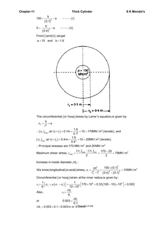
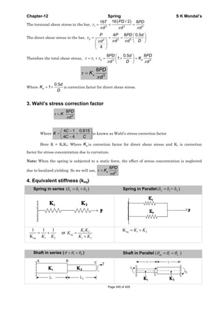
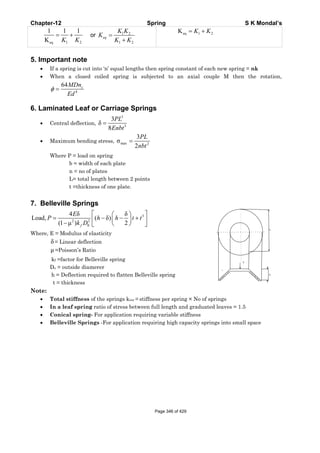
![Chapter-12 Spring S K Mondal’s
OBJECTIVE QUESTIONS (GATE, IES, IAS)
Previous 20-Years GATE Questions
Helical spring
GATE-1. If the wire diameter of a closed coil helical spring subjected to compressive
load is increased from 1 cm to 2 cm, other parameters remaining same, then
deflection will decrease by a factor of: [GATE-2002]
(a) 16 (b) 8 (c) 4 (d) 2
GATE-1. Ans. (a)
3
4
8PD N
G.d
δ =
GATE-2. A compression spring is made of music wire of 2 mm diameter having a shear
strength and shear modulus of 800 MPa and 80 GPa respectively. The mean coil
diameter is 20 mm, free length is 40 mm and the number of active coils is 10. If
the mean coil diameter is reduced to 10 mm, the stiffness of the spring is
approximately [GATE-2008]
(a) Decreased by 8 times (b) Decreased by 2 times
(c) Increased by 2 times (d) Increased by 8 times
GATE-2. Ans. (d) Spring constant (K) =
ND
dGP
3
4
8
.
=
δ
or K∝ 3
1
D
8
10
20
33
2
1
1
2
=⎟
⎠
⎞
⎜
⎝
⎛
=⎟⎟
⎠
⎞
⎜⎜
⎝
⎛
=
D
D
K
K
GATE-3. Two helical tensile springs of the same material and also having identical mean
coil diameter and weight, have wire diameters d and d/2. The ratio of their
stiffness is: [GATE-2001]
(a) 1 (b) 4 (c) 64 (d) 128
GATE-3. Ans. (c) Spring constant (K) =
ND
dGP
3
4
8
.
=
δ
Therefore
4
d
k
n
∞
GATE-4. A uniform stiff rod of length 300 mm
and having a weight of 300 N is
pivoted at one end and connected to
a spring at the other end. For
keeping the rod vertical in a stable
position the minimum value of
spring constant K needed is:
(a) 300 N/m (b) 400N/m
(c) 500N/m (d) 1000 N/m
[GATE-2004]
GATE-4. Ans. (c) Inclined it to a very low angle, dθ
For equilibrium taking moment about ‘hinge’
( )
l W 300
W d k ld l 0 or k 500N / m
2 2l 2 0.3
θ θ
⎛ ⎞
× − × = = = =⎜ ⎟ ×⎝ ⎠
GATE-5. A weighing machine consists of a 2 kg pan resting on spring. In this condition,
with the pan resting on the spring, the length of the spring is 200 mm. When a
mass of 20 kg is placed on the pan, the length of the spring becomes 100 mm.
For the spring, the un-deformed length lo and the spring constant k (stiffness)
are: [GATE-2005]
Page 347 of 429](https://image.slidesharecdn.com/strengthofmaterialsbyskmondal-130102103545-phpapp02-150924095946-lva1-app6891/85/Strengthofmaterialsbyskmondal-130102103545-phpapp02-347-320.jpg)
![Chapter-12 Spring S K Mondal’s
(a) lo = 220 mm, k = 1862 N/m (b) lo = 210 mm, k = 1960 N/m
(c) lo = 200 mm, k = 1960 N/m (d) lo = 200 mm, k = 2156 N/m
GATE-5. Ans. (b) Initial length = lo m and stiffness = k N/m
( )
( )
o
o
2 g k l 0.2
2 g 20 g k l 0.1
× = −
× + × = −
Just solve the above equations.
Springs in Series
GATE-6. The deflection of a spring with 20 active turns under a load of 1000 N is 10 mm.
The spring is made into two pieces each of 10 active coils and placed in parallel
under the same load. The deflection of this system is: [GATE-1995]
(a) 20 mm (b) 10 mm (c) 5 mm (d) 2.5 mm
GATE-6. Ans. (d) When a spring is cut into two, no. of coils gets halved.
∴ Stiffness of each half gets doubled.
When these are connected in parallel, stiffness = 2k + 2k = 4k
Therefore deflection will be ¼ times. = 2.5 mm
Previous 20-Years IES Questions
Helical spring
IES-1. A helical coil spring with wire diameter ’d’ and coil diameter 'D' is subjected to
external load. A constant ratio of d and D has to be maintained, such that the
extension of spring is independent of d and D. What is this ratio? [IES-2008]
4/3 4/3
3 4 3 4
3 3
D d
(a)D / d (b)d / D (c) (d)
d D
IES-1. Ans. (a)
3
4
8PD N
Gd
δ =
= × = θ
θ =
= π
⎛ ⎞ ⎛ ⎞
= =⎜ ⎟ ⎜ ⎟
⎝ ⎠ ⎝ ⎠
∂
δ = =
∂
2 2 3
4
3
4
D 1
T F ; U T
2 2
FD TL
Τ = ;
2 GJ
L DN
1 FD L 4F D N
U
2 2 GJ Gd
U 8FD N
F Gd
IES-2. Assertion (A): Concentric cylindrical helical springs are used to have greater
spring force in a limited space. [IES-2006]
Reason (R): Concentric helical springs are wound in opposite directions to
prevent locking of coils under heavy dynamic loading.
(a) Both A and R are individually true and R is the correct explanation of A
(b) Both A and R are individually true but R is NOT the correct explanation of A
(c) A is true but R is false
(d) A is false but R is true
IES-2. Ans. (b)
IES-3. Assertion (A): Two concentric helical springs used to provide greater spring
force are wound in opposite directions. [IES-1995; IAS-2004]
Reason (R): The winding in opposite directions in the case of helical springs
prevents buckling.
(a) Both A and R are individually true and R is the correct explanation of A
(b) Both A and R are individually true but R is NOT the correct explanation of A
Page 348 of 429](https://image.slidesharecdn.com/strengthofmaterialsbyskmondal-130102103545-phpapp02-150924095946-lva1-app6891/85/Strengthofmaterialsbyskmondal-130102103545-phpapp02-348-320.jpg)
![Chapter-12 Spring S K Mondal’s
(c) A is true but R is false
(d) A is false but R is true
IES-3. Ans. (c) It is for preventing locking not for buckling.
IES-4. Which one of the following statements is correct? [IES-1996; 2007; IAS-1997]
If a helical spring is halved in length, its spring stiffness
(a) Remains same (b) Halves (c) Doubles (d) Triples
IES-4. Ans. (c) ( )
4
3
Gd 1
Stiffness of sprin k so k andnwiil behalf
n8D n
= ∞
IES-5. A body having weight of 1000 N is dropped from a height of 10 cm over a close-
coiled helical spring of stiffness 200 N/cm. The resulting deflection of spring is
nearly [IES-2001]
(a) 5 cm (b) 16 cm (c) 35 cm (d) 100 cm
IES-5. Ans. (b)
21
mg(h x) kx
2
+ =
IES-6. A close-coiled helical spring is made of 5 mm diameter wire coiled to 50 mm
mean diameter. Maximum shear stress in the spring under the action of an
axial force is 20 N/mm2. The maximum shear stress in a spring made of 3 mm
diameter wire coiled to 30 mm mean diameter, under the action of the same
force will be nearly [IES-2001]
(a) 20 N/mm2 (b) 33.3 N/mm2 (c) 55.6 N/mm2 (d) 92.6 N/mm2
IES-6. Ans. (c) s 3
8PD
Use k
d
τ
π
=
IES-7. A closely-coiled helical spring is acted upon by an axial force. The maximum
shear stress developed in the spring is τ . Half of the length of the spring is cut
off and the remaining spring is acted upon by the same axial force. The
maximum shear stress in the spring the new condition will be: [IES-1995]
(a) ½ τ (b) τ (c) 2 τ (d) 4 τ
IES-7. Ans. (b) s 3
8PD
Use k
d
τ
π
= it is independent of number of turn
IES-8. The maximum shear stress occurs on the outermost fibers of a circular shaft
under torsion. In a close coiled helical spring, the maximum shear stress
occurs on the [IES-1999]
(a) Outermost fibres (b) Fibres at mean diameter (c) Innermost fibres (d) End coils
IES-8. Ans. (c)
IES-9. A helical spring has N turns of coil of diameter D, and a second spring, made of
same wire diameter and of same material, has N/2 turns of coil of diameter 2D.
If the stiffness of the first spring is k, then the stiffness of the second spring
will be: [IES-1999]
(a) k/4 (b) k/2 (c) 2k (d) 4k
IES-9. Ans. (a)
( )
4 4
23
3
Stiffness (k) ; econd spring,stiffness (k )=
64 464 2
2
Gd Gd k
S
NR N R
= =
×
IES-10. A closed-coil helical spring is subjected to a torque about its axis. The spring
wire would experience a [IES-1996; 1998]
(a) Bending stress
(b) Direct tensile stress of uniform intensity at its cross-section
(c) Direct shear stress
(d) Torsional shearing stress
IES-10. Ans. (a)
IES-11. Given that: [IES-1996]
d = diameter of spring, R = mean radius of coils, n = number of coils and G =
modulus of rigidity, the stiffness of the close-coiled helical spring subject to an
axial load W is equal to Page 349 of 429](https://image.slidesharecdn.com/strengthofmaterialsbyskmondal-130102103545-phpapp02-150924095946-lva1-app6891/85/Strengthofmaterialsbyskmondal-130102103545-phpapp02-349-320.jpg)
![Chapter-12 Spring S K Mondal’s
(a)
4
3
64
Gd
R n
(b)
3
3
64
Gd
R n
(c)
4
3
32
Gd
R n
(d)
4
2
64
Gd
R n
IES-11. Ans. (a)
IES-12. A closely coiled helical spring of 20 cm mean diameter is having 25 coils of 2 cm
diameter rod. The modulus of rigidity of the material if 107 N/cm2. What is the
stiffness for the spring in N/cm? [IES-2004]
(a) 50 (b) 100 (c) 250 (d) 500
IES-12. Ans. (b) ( )
( ) ( )
( )
7 2 4 44
3 3 3
10 N / cm 2 cmGd
Stiffness of sprin k 100N / cm
8D n 8 20 cm 25
×
= = =
× ×
IES-13. Which one of the following expresses the stress factor K used for design of
closed coiled helical spring? [IES-2008]
4C 4 4C 1 0.615 4C 4 0.615 4C 1
(a) (b) (c) (d)
4C 1 4C 4 C 4C 1 C 4C 4
− − − −
+ +
− − − −
Where C = spring index
IES-13. Ans. (b)
IES-14. In the calculation of induced shear stress in helical springs, the Wahl's
correction factor is used to take care of [IES-1995; 1997]
(a) Combined effect of transverse shear stress and bending stresses in the wire.
(b) Combined effect of bending stress and curvature of the wire.
(c) Combined effect of transverse shear stress and curvature of the wire.
(d) Combined effect of torsional shear stress and transverse shear stress in the wire.
IES-14. Ans. (c)
IES-15. While calculating the stress induced in a closed coil helical spring, Wahl's
factor must be considered to account for [IES-2002]
(a) The curvature and stress concentration effect (b) Shock loading
(c) Poor service conditions (d) Fatigue loading
IES-15. Ans. (a)
IES-16. Cracks in helical springs used in Railway carriages usually start on the inner
side of the coil because of the fact that [IES-1994]
(a) It is subjected to the higher stress than the outer side.
(b) It is subjected to a higher cyclic loading than the outer side.
(c) It is more stretched than the outer side during the manufacturing process.
(d) It has a lower curvature than the outer side.
IES-16. Ans. (a)
IES-17. Two helical springs of the same material and of equal circular cross-section
and length and number of turns, but having radii 20 mm and 40 mm, kept
concentrically (smaller radius spring within the larger radius spring), are
compressed between two parallel planes with a load P. The inner spring will
carry a load equal to [IES-1994]
(a) P/2 (b) 2P/3 (c) P/9 (d) 8P/9
IES-17. Ans. (d)
33
3
20 1 8
;
40 8 8 8 9
o i i i
o i i
i o
W R W W
W So W P or W P
W R
⎛ ⎞
= = = = + = =⎜ ⎟
⎝ ⎠
IES-18. A length of 10 mm diameter steel wire is coiled to a close coiled helical spring
having 8 coils of 75 mm mean diameter, and the spring has a stiffness K. If the
same length of wire is coiled to 10 coils of 60 mm mean diameter, then the
spring stiffness will be: [IES-1993]
(a) K (b) 1.25 K (c) 1.56 K (d) 1.95 K
IES-18. Ans. (c)
4
3
Stiffnessof spring (k) Where G and d issame
64
=
Gd
R n
Page 350 of 429](https://image.slidesharecdn.com/strengthofmaterialsbyskmondal-130102103545-phpapp02-150924095946-lva1-app6891/85/Strengthofmaterialsbyskmondal-130102103545-phpapp02-350-320.jpg)
![Chapter-12 Spring S K Mondal’s
3 3
2
2 2
1 1 1
Therefore
1.5675 8
60 10
= = =
⎛ ⎞ ⎛ ⎞ ⎛ ⎞ ⎛ ⎞
⎜ ⎟ ⎜ ⎟⎜ ⎟ ⎜ ⎟
⎝ ⎠ ⎝ ⎠⎝ ⎠ ⎝ ⎠
k
k R n
R n
IES-19. A spring with 25 active coils cannot be accommodated within a given space.
Hence 5 coils of the spring are cut. What is the stiffness of the new spring?
(a) Same as the original spring (b) 1.25 times the original spring [IES-2004]
(c) 0.8 times the original spring (d) 0.5 times the original spring
IES-19. Ans. (b) ( )
4
3
Gd
Stiffness of spring k
8D n
= 2 1
1 2
k n1 25
k or 1.25
n k n 20
α∴ = = =
IES-20. Wire diameter, mean coil diameter and number of turns of a closely-coiled steel
spring are d, D and N respectively and stiffness of the spring is K. A second
spring is made of same steel but with wire diameter, mean coil diameter and
number of turns 2d, 2D and 2N respectively. The stiffness of the new spring is:
[IES-1998; 2001]
(a) K (b) 2K (c) 4K (d) 8K
IES-20. Ans. (a) ( )
4
3
Gd
Stiffness of spring k
8D n
=
IES-21. When two springs of equal lengths are arranged to form cluster springs which
of the following statements are the: [IES-1992]
1. Angle of twist in both the springs will be equal
2. Deflection of both the springs will be equal
3. Load taken by each spring will be half the total load
4. Shear stress in each spring will be equal
(a) 1 and 2 only (b) 2 and 3 only (c) 3 and 4 only (d) 1, 2 and 4 only
IES-21. Ans. (a)
IES-22. Consider the following statements: [IES-2009]
When two springs of equal lengths are arranged to form a cluster spring
1. Angle of twist in both the springs will be equal
2. Deflection of both the springs will be equal
3. Load taken by each spring will be half the total load
4. Shear stress in each spring will be equal
Which of the above statements is/are correct?
(a) 1 and 2 (b) 3 and 4 (c)2 only (d) 4 only
IES-22. Ans. (a) Same as [IES-1992]
Page 351 of 429](https://image.slidesharecdn.com/strengthofmaterialsbyskmondal-130102103545-phpapp02-150924095946-lva1-app6891/85/Strengthofmaterialsbyskmondal-130102103545-phpapp02-351-320.jpg)
![Chapter-12 Spring S K Mondal’s
Close-coiled helical spring with axial load
IES-23. Under axial load, each section of a close-coiled helical spring is subjected to
(a) Tensile stress and shear stress due to load [IES-2003]
(b) Compressive stress and shear stress due to torque
(c) Tensile stress and shear stress due to torque
(d) Torsional and direct shear stresses
IES-23. Ans. (d)
IES-24. When a weight of 100 N falls on a spring of stiffness 1 kN/m from a height of 2
m, the deflection caused in the first fall is: [IES-2000]
(a) Equal to 0.1 m (b) Between 0.1 and 0.2 m
(c) Equal to 0.2 m (d) More than 0.2 m
IES-24. Ans. (d) use ( ) 21
mg h x kx
2
+ =
Subjected to 'Axial twist'
IES-25. A closed coil helical spring of mean coil diameter 'D' and made from a wire of
diameter 'd' is subjected to a torque 'T' about the axis of the spring. What is the
maximum stress developed in the spring wire? [IES-2008]
π π π π3 3 3 3
8T 16T 32T 64T
(a) (b) (c) (d)
d d d d
IES-25. Ans. (b)
Springs in Series
IES-26. When a helical compression spring is cut into two equal halves, the stiffness of
each of the result in springs will be: [IES-2002; IAS-2002]
(a) Unaltered (b) Double (c) One-half (d) One-fourth
IES-26. Ans. (b)
IES-27. If a compression coil spring is cut into two equal parts and the parts are then
used in parallel, the ratio of the spring rate to its initial value will be:[IES-1999]
Page 352 of 429](https://image.slidesharecdn.com/strengthofmaterialsbyskmondal-130102103545-phpapp02-150924095946-lva1-app6891/85/Strengthofmaterialsbyskmondal-130102103545-phpapp02-352-320.jpg)
![Chapter-12 Spring S K Mondal’s
(a) 1 (b) 2 (c) 4 (d) Indeterminable for want of sufficient data
IES-27. Ans. (c) When a spring is cut into two, no. of coils gets halved.
∴ Stiffness of each half gets doubled.
When these are connected in parallel, stiffness = 2k + 2k = 4k
Springs in Parallel
IES-28. The equivalent spring stiffness for the
system shown in the given figure (S is
the spring stiffness of each of the three
springs) is:
(a) S/2 (b) S/3
(c) 2S/3 (d) S
[IES-1997; IAS-2001]
IES-28. Ans. (c)
1 1 1 2
2 3
e
e
or S S
S S S
= + =
IES-29. Two coiled springs, each having stiffness K, are placed in parallel. The stiffness
of the combination will be: [IES-2000]
( ) ( ) ( ) ( )a 4 b 2 c d
2 4
K K
K K
IES-29. Ans. (b) 1 2W k k kδ δ δ= = +
IES-30. A mass is suspended at the bottom of two springs in series having stiffness 10
N/mm and 5 N/mm. The equivalent spring stiffness of the two springs is nearly
[IES-2000]
(a) 0.3 N/mm (b) 3.3 N/mm (c) 5 N/mm (d) 15 N/mm
IES-30. Ans. (b)
1 1 1 10
10 5 3
= + =e
e
or S
S Page 353 of 429](https://image.slidesharecdn.com/strengthofmaterialsbyskmondal-130102103545-phpapp02-150924095946-lva1-app6891/85/Strengthofmaterialsbyskmondal-130102103545-phpapp02-353-320.jpg)
![Chapter-12 Spring S K Mondal’s
IES-31. Figure given above shows a spring-
mass system where the mass m is
fixed in between two springs of
stiffness S1 and S2. What is the
equivalent spring stiffness?
(a) S1- S2 (b) S1+ S2
(c) (S1+ S2)/ S1 S2 (d) (S1- S2)/
S1 S2
[IES-2005]
IES-31. Ans. (b)
IES-32. Two identical springs
labelled as 1 and 2 are
arranged in series and
subjected to force F as
shown in the given
figure.
Assume that each spring constant is K. The strain energy stored in spring 1 is:
[IES-2001]
(a)
2
2
F
K
(b)
2
4
F
K
(c)
2
8
F
K
(d)
2
16
F
K
IES-32. Ans. (c) The strain energy stored per spring =
2
21 1
. / 2 / 2
2 2
eq
eq
F
k x k
k
⎛ ⎞
= × ×⎜ ⎟⎜ ⎟
⎝ ⎠
and here total
force ‘F’ is supported by both the spring 1 and 2 therefore keq = k + k =2k
IES-33. What is the equivalent stiffness (i.e. spring
constant) of the system shown in the given
figure?
(a) 24 N/mm (b) 16 N/mm
(c) 4 N/mm (d) 5.3 N/mm
[IES-1997]
IES-33. Ans. (a) Stiffness K1 of 10 coils spring = 8 N/mm
∴ Stiffness K2 of 5 coils spring = 16 N/mm
Though it looks like in series but they are in parallel combination. They are not subjected
to same force. Equivalent stiffness (k) = k1 + k2 = 24 N/mm
Previous 20-Years IAS Questions
Helical spring
IAS-1. Assertion (A): Concentric cylindrical helical springs which are used to have
greater spring force in a limited space is wound in opposite directions.Page 354 of 429](https://image.slidesharecdn.com/strengthofmaterialsbyskmondal-130102103545-phpapp02-150924095946-lva1-app6891/85/Strengthofmaterialsbyskmondal-130102103545-phpapp02-354-320.jpg)
![Chapter-12 Spring S K Mondal’s
Reason (R): Winding in opposite directions prevents locking of the two coils in
case of misalignment or buckling. [IAS-1996]
(a) Both A and R are individually true and R is the correct explanation of A
(b) Both A and R are individually true but R is NOT the correct explanation of A
(c) A is true but R is false
(d) A is false but R is true
IAS-1. Ans. (a)
IAS-2. An open-coiled helical spring of mean diameter D, number of coils N and wire
diameter d is subjected to an axial force' P. The wire of the spring is subject to:
[IAS-1995]
(a) direct shear only (b) combined shear and bending only
(c) combined shear, bending and twisting (d) combined shear and twisting only
IAS-2. Ans. (d)
IAS-3. Assertion (A): Two concentric helical springs used to provide greater spring
force are wound in opposite directions. [IES-1995; IAS-2004]
Reason (R): The winding in opposite directions in the case of helical springs
prevents buckling.
(a) Both A and R are individually true and R is the correct explanation of A
(b) Both A and R are individually true but R is NOT the correct explanation of A
(c) A is true but R is false
(d) A is false but R is true
IAS-3. Ans. (c) It is for preventing locking not for buckling.
IAS-4. Which one of the following statements is correct? [IES-1996; 2007; IAS-1997]
If a helical spring is halved in length, its spring stiffness
(a) Remains same (b) Halves (c) Doubles (d) Triples
IAS-4. Ans. (c) ( )
4
3
Gd 1
Stiffness of sprin k so k andnwiil behalf
n8D n
= ∞
IAS-5. A closed coil helical spring has 15 coils. If five coils of this spring are removed
by cutting, the stiffness of the modified spring will: [IAS-2004]
(a) Increase to 2.5 times (b) Increase to 1.5 times
(c) Reduce to 0.66 times (d) Remain unaffected
IAS-5. Ans. (b) K=
4
2 1
3
1 2
1 15
1.5
8 10
K NGd
or K or
D N N K N
α = = =
IAS-6. A close-coiled helical spring has wire diameter 10 mm and spring index 5. If the
spring contains 10 turns, then the length of the spring wire would be: [IAS-2000]
(a) 100 mm (b) 157 mm (c) 500 mm (d) 1570 mm
IAS-6. Ans. (d) ( ) ( )5 10 10 1570l Dn cd n mmπ π π= = = × × × =
IAS-7. Consider the following types of stresses: [IAS-1996]
1. torsional shear 2. Transverse direct shear 3. Bending stress
The stresses, that are produced in the wire of a close-coiled helical spring
subjected to an axial load, would include
(a) 1 and 3 (b) 1 and 2 (c) 2 and 3 (d) 1, 2 and 3
IAS-7. Ans. (b)
IAS-8. Two close-coiled springs are subjected to the same axial force. If the second
spring has four times the coil diameter, double the wire diameter and double
the number of coils of the first spring, then the ratio of deflection of the second
spring to that of the first will be: [IAS-1998]
(a) 8 (b) 2 (c)
1
2
(d) 1/16
Page 355 of 429](https://image.slidesharecdn.com/strengthofmaterialsbyskmondal-130102103545-phpapp02-150924095946-lva1-app6891/85/Strengthofmaterialsbyskmondal-130102103545-phpapp02-355-320.jpg)
![Chapter-12 Spring S K Mondal’s
IAS-8. Ans. (a)
2 2
3 3
1 12
4 4 4
1 2
1
D N
D N8PD N 4 2
or 8
Gd 2d
d
δ
δ
δ
⎛ ⎞⎛ ⎞
⎜ ⎟⎜ ⎟
×⎝ ⎠⎝ ⎠= = = =
⎛ ⎞
⎜ ⎟
⎝ ⎠
IAS-9. A block of weight 2 N falls from a height of 1m on the top of a spring· If the
spring gets compressed by 0.1 m to bring the weight momentarily to rest, then
the spring constant would be: [IAS-2000]
(a) 50 N/m (b) 100 N/m (c) 200N/m (d) 400N/m
IAS-9. Ans. (d) Kinetic energy of block = potential energy of spring
or
2
2 2
1 2 2 2 1
. / 400 /
2 0.1
Wh
W h k x or k N m N m
x
× ×
× = = = =
IAS-10. The springs of a chest expander are 60 cm long when unstretched. Their
stiffness is 10 N/mm. The work done in stretching them to 100 cm is: [IAS-1996]
(a) 600 Nm (b) 800 Nm (c) 1000 Nm (d) 1600 Nm
IAS-10. Ans. (b) { }
22 21 1 10N
E kx 1 0.6 m 800Nm
12 2
m
1000
⎧ ⎫
⎪ ⎪⎪ ⎪
= = × × − =⎨ ⎬
⎛ ⎞⎪ ⎪
⎜ ⎟⎪ ⎪⎝ ⎠⎩ ⎭
IAS-11. A spring of stiffness 'k' is extended from a displacement x1 to a displacement x2
the work done by the spring is: [IAS-1999]
(a)
2 2
1 2
1 1
2 2
−k x k x (b)
2
1 2
1
( )
2
−k x x (c)
2
1 2
1
( )
2
+k x x (d)
2
1 2
2
x x
k
+⎛ ⎞
⎜ ⎟
⎝ ⎠
IAS-11. Ans. (a) Work done by the spring is = −2 2
1 2
1 1
k x k x
2 2
IAS-12. A spring of stiffness 1000 N/m is stretched initially by 10 cm from the
undeformed position. The work required to stretch it by another 10 cm is:
[IAS-1995]
(a) 5 Nm (b) 7 Nm (c) 10 Nm (d) 15 Nm.
IAS-12. Ans. (d) ( ) { }2 2 2 2
2 1
1 1
E k x x 1000 0.20 0.10 15Nm
2 2
= − = × × − =
Springs in Series
IAS-13. When a helical compression spring is cut into two equal halves, the stiffness of
each of the result in springs will be: [IES-2002; IAS-2002]
(a) Unaltered (b) Double (c) One-half (d) One-fourth
IAS-13. Ans. (b)
IAS-14. The length of the chest-expander spring when it is un-stretched, is 0.6 m and its
stiffness is 10 N/mm. The work done in stretching it to 1m will be: [IAS-2001]
(a) 800 J (b) 1600 J (c) 3200 J (d) 6400 J
IAS-14. Ans. (a)
Work done = ( )
22 2 2 21 1 10N 1 10
k.x 1 0.6 m 0.4 800
12 2 1mm 2
1000
⎛ ⎞
= × × − = × × =⎜ ⎟
⎛ ⎞⎝ ⎠
⎜ ⎟
⎝ ⎠
N
m J
m
Page 356 of 429](https://image.slidesharecdn.com/strengthofmaterialsbyskmondal-130102103545-phpapp02-150924095946-lva1-app6891/85/Strengthofmaterialsbyskmondal-130102103545-phpapp02-356-320.jpg)
![Chapter-12 Spring S K Mondal’s
Springs in Parallel
IAS-15. The equivalent spring stiffness for the
system shown in the given figure (S is
the spring stiffness of each of the three
springs) is:
(a) S/2 (b) S/3
(c) 2S/3 (d) S
[IES-1997; IAS-2001]
IAS-15. Ans. (c)
1 1 1 2
2 3
e
e
or S S
S S S
= + =
IAS-16. Two identical springs, each of stiffness K, are
assembled as shown in the given figure. The
combined stiffness of the assembly is:
(a) K2 (b) 2K
(c) K (d) (1/2)K
[IAS-1998]
IAS-16. Ans. (b) Effective stiffness = 2K. Due to applied force one spring will be under tension and
another one under compression so total resistance force will double.
Flat spiral Spring
IAS-17. Mach List-I (Type of spring) with List-II (Application) and select the correct
answer: [IAS-2000]
List-I List-II
A. Leaf/Helical springs 1. Automobiles/Railways coachers
B. Spiral springs 2. Shearing machines
C. Belleville springs 3. Watches
Codes: A B C A B C
(a) 1 2 3 (b) 1 3 2
(c) 3 1 2 (d) 2 3 1
IAS-17. Ans. (b)
Page 357 of 429](https://image.slidesharecdn.com/strengthofmaterialsbyskmondal-130102103545-phpapp02-150924095946-lva1-app6891/85/Strengthofmaterialsbyskmondal-130102103545-phpapp02-357-320.jpg)
![Chapter-12 Spring S K Mondal’s
Semi-elliptical spring
IAS-18. The ends of the leaves of a semi-elliptical leaf spring are made triangular in
plain in order to: [IAS 1994]
(a) Obtain variable I in each leaf
(b) Permit each leaf to act as a overhanging beam
(c) Have variable bending moment in each leaf
(d) Make Mil constant throughout the length of the leaf.
IAS-18. Ans. (d) The ends of the leaves of a semi-elliptical leaf spring are made rectangular in plan
in order to make M/I constant throughout the length of the leaf.
Page 358 of 429](https://image.slidesharecdn.com/strengthofmaterialsbyskmondal-130102103545-phpapp02-150924095946-lva1-app6891/85/Strengthofmaterialsbyskmondal-130102103545-phpapp02-358-320.jpg)
![Chapter-12 Spring S K Mondal’s
Previous Conventional Questions with Answers
Conventional Question ESE-2008
Question: A close-coiled helical spring has coil diameter D, wire diameter d and number
of turn n. The spring material has a shearing modulus G. Derive an
expression for the stiffness k of the spring.
Answer: The work done by the
axial force 'P' is
converted into strain
energy and stored in
the spring.
( )
( )
U= average torque
× angular displacement
T
= ×θ
2
TL
From the figure we get, θ =
GJ
PD
Torque (T)=
2
4
2 3
4
length of wire (L)=πDn
πd
Polar moment of Inertia(J)=
32
4P D n
Therefore U=
Gd
According to Castigliano's theorem, the displacement corresponding to force P is
obtained by partially differentiating strain energy with respect to that force.
( )
2 3 3
4 4
4
3
4 8U
Therefore =
P
So Spring stiffness, k =
8
p D n PD n
P P Gd Gd
Gd
D n
δ
δ
⎡ ⎤∂∂ ⎢ ⎥= =
⎢ ⎥∂ ∂ ⎣ ⎦
=
Conventional Question ESE-2010
Q. A stiff bar of negligible weight transfers a load P to a combination of three
helical springs arranged in parallel as shown in the above figure. The springs
are made up of the same material and out of rods of equal diameters. They are
of same free length before loading. The number of coils in those three springs
are 10, 12 and 15 respectively, while the mean coil diameters are in ratio of 1 :
1.2 : 1.4 respectively. Find the distance ‘x’ as shown in figure, such that the stiff
bar remains horizontal after the application of load P. [10 Marks]
l l
x
P
Ans. Same free length of spring before loading
Page 359 of 429](https://image.slidesharecdn.com/strengthofmaterialsbyskmondal-130102103545-phpapp02-150924095946-lva1-app6891/85/Strengthofmaterialsbyskmondal-130102103545-phpapp02-359-320.jpg)
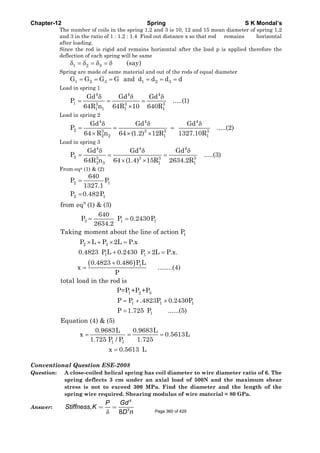
![Chapter-12 Spring S K Mondal’s
( )9
3
4
80 10500 D
, [ c= 6]
0.03 8 6 d
, 3.6 10 ( )
d
or given
n
or d n i−
× ×
= =
× ×
= × −−−
static loading correcting factor(k)
0.5 0.5
k= 1+ 1 1.0833
c 6
For
⎛ ⎞ ⎛ ⎞⎟ ⎟⎜ ⎜= + =⎟ ⎟⎜ ⎜⎟ ⎟⎜ ⎜⎝ ⎠ ⎝ ⎠
( )
π
d
π
3
2
8PD
know that =k
d
8
6
We
kPC D
C
d
τ
τ
⎡ ⎤
⎢ ⎥= = =
⎢ ⎥⎣ ⎦
∵
3
6
1.0833 8 500 6
5.252 10 5.252
300 10
D=cd=6×5.252mm=31.513mm
d m mm
So
π
−× × ×
= = × =
× ×
π π×
From, equation (i) n=14.59 15
Now length of spring wire(L) = Dn = 31.513×15 mm =1.485 m
Conventional Question ESE-2007
Question: A coil spring of stiffness 'k' is cut to two halves and these two springs are
assembled in parallel to support a heavy machine. What is the combined
stiffness provided by these two springs in the modified arrangement?
Answer: When it cut to two halves stiffness of
each half will be 2k. Springs in parallel.
Total load will be shared so
Total load = W+W
δ δ δ. .(2 ) .(2 )
4 .
eq
eq
or K k k
or K k
= +
=
Conventional Question ESE-2001
Question: A helical spring B is placed inside the coils of a second helical spring A ,
having the same number of coils and free axial length and of same material.
The two springs are compressed by an axial load of 210 N which is shared
between them. The mean coil diameters of A and B are 90 mm and 60 mm and
the wire diameters are 12 mm and 7 mm respectively. Calculate the load
shared by individual springs and the maximum stress in each spring.
Answer:
4
3
Gd
The stiffness of the spring (k) =
8D N
⎛ ⎞ ⎛ ⎞ ⎛ ⎞ ⎛ ⎞⎟ ⎟⎜ ⎜ ⎟ ⎟⎜ ⎜⎟ ⎟ = = × =⎜ ⎜ ⎟ ⎟⎜ ⎜⎟ ⎟ ⎟ ⎟⎜ ⎜ ⎜ ⎜⎟ ⎟⎜ ⎜ ⎝ ⎠ ⎝ ⎠⎝ ⎠ ⎝ ⎠
e A B
4 3 4 3
A A
A
B B A
Here load shared the springs are arranged in parallel
Equivalent stiffness(k )=k +k
K d 12 60
Hear = [As N ] 2.559
K d 7 90
N
D
N
D
B
= =
+
Total load 210
Let total deflection is 'x' m x
Equivalet stiffness A B
N
K K
Page 361 of 429](https://image.slidesharecdn.com/strengthofmaterialsbyskmondal-130102103545-phpapp02-150924095946-lva1-app6891/85/Strengthofmaterialsbyskmondal-130102103545-phpapp02-361-320.jpg)
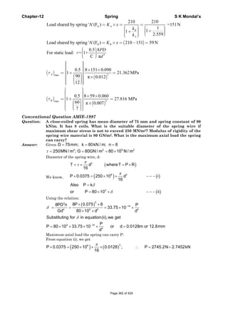

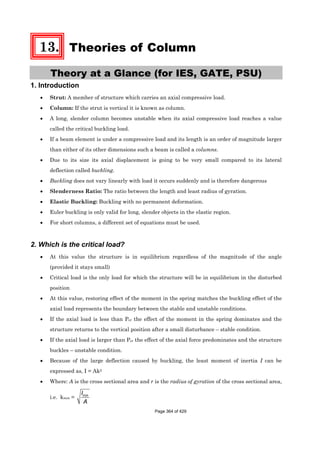
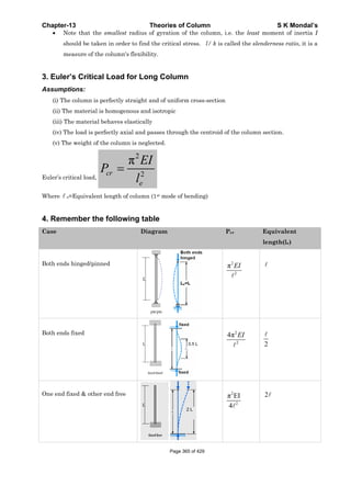
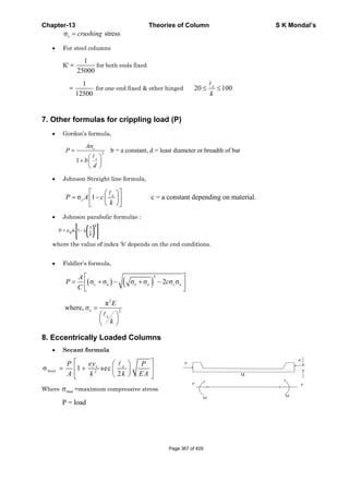
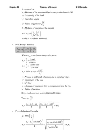
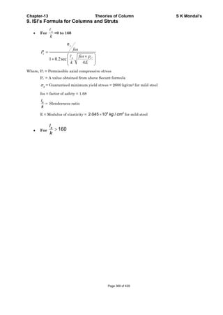
![Chapter-13 Theories of Column S K Mondal’s
OBJECTIVE QUESTIONS (GATE, IES, IAS)
Previous 20-Years GATE Questions
Strength of Column
GATE-1. The rod PQ of length L and with
flexural rigidity EI is hinged at
both ends. For what minimum
force F is it expected to buckle?
(a) 2
2
L
EIπ
(b)
2
2
2 EI
L
π
(c)
2
2
2L
EIπ
(b) 2
2
2L
EIπ
[GATE-2008]
GATE-1. Ans. (b) Axial component of the force FPQ = F Sin 450
We know for both end fixed column buckling load (P) = 2
2
L
EIπ
and 0
Fsin45 = P or F =
2
2
2 EI
L
π
Equivalent Length
GATE-2. The ratio of Euler's buckling loads of columns with the same parameters
having (i) both ends fixed, and (ii) both ends hinged is:
[GATE-1998; 2002; IES-2001]
(a) 2 (b) 4 (c) 6 (d) 8
GATE-2. Ans. (b) Euler’s buckling loads of columns
( )
( )
2
2
2
2
4 EI
1 both ends fixed
l
EI
2 both ends hinged
l
π
π
=
=
Euler's Theory (For long column)
GATE-3. A pin-ended column of length L, modulus of elasticity E and second moment of
the cross-sectional area I is loaded centrically by a compressive load P. The
critical buckling load (Pcr) is given by: [GATE-2006]
(a) 2 2cr
EI
P
Lπ
= (b)
2
2
3
cr
EI
P
L
π
= (c) 2cr
EI
P
L
π
= (d)
2
2cr
EI
P
L
π
=
GATE-3. Ans. (d)
GATE-4. What is the expression for the crippling load for a column of length ‘l’ with one
end fixed and other end free? [IES-2006; GATE-1994]
(a)
2
2
2 EI
P
l
π
= (b)
2
2
4
EI
P
l
π
= (c)
2
2
4 EI
P
l
π
= (d)
2
2
EI
P
l
π
=Page 370 of 429](https://image.slidesharecdn.com/strengthofmaterialsbyskmondal-130102103545-phpapp02-150924095946-lva1-app6891/85/Strengthofmaterialsbyskmondal-130102103545-phpapp02-370-320.jpg)
![Chapter-13 Theories of Column S K Mondal’s
GATE-4. Ans. (b)
21. The piston rod of diameter 20 mm and length 700 mm in a hydraulic cylinder is subjected to
a compressive force of 10 KN due to the internal pressure. The end conditions for the rod may
be assumed as guided at the piston end and hinged at the other end. The Young’s modulus is
200 GPa. The factor of safety for the piston rod is
(a) 0.68 (b) 2.75 (c) 5.62 (d) 11.0 [GATE-2007]
21. Ans. (c)
Previous 20-Years IES Questions
Classification of Column
IES-1. A structural member subjected to an axial compressive force is called
[IES-2008]
(a) Beam (b) Column (c) Frame (d) Strut
IES-1. Ans. (d) A machine part subjected to an axial compressive force is called a strut. A strut may
be horizontal, inclined or even vertical. But a vertical strut is known as a column,
pillar or stanchion.
The term column is applied to all such members except those in which failure would be
by simple or pure compression. Columns can be categorized then as:
1. Long column with central loading
2. Intermediate-length columns with central loading
3. Columns with eccentric loading
4. Struts or short columns with eccentric loading
IES-2. Which one of the following loadings is considered for design of axles?
(a) Bending moment only [IES-1995]
(b) Twisting moment only
(c) Combined bending moment and torsion
(d) Combined action of bending moment, twisting moment and axial thrust.
IES-2. Ans. (a) Axle is a non-rotating member used for supporting rotating wheels etc. and do not
transmit any torque. Axle must resist forces applied laterally or transversely to their
axes. Such members are called beams.
Page 371 of 429](https://image.slidesharecdn.com/strengthofmaterialsbyskmondal-130102103545-phpapp02-150924095946-lva1-app6891/85/Strengthofmaterialsbyskmondal-130102103545-phpapp02-371-320.jpg)
![Chapter-13 Theories of Column S K Mondal’s
IES-3. The curve ABC is the Euler's
curve for stability of column. The
horizontal line DEF is the
strength limit. With reference to
this figure Match List-I with List-
II and select the correct answer
using the codes given below the
lists:
List-I List-II
(Regions) (Column specification)
A. R1 1. Long, stable
B. R2 2. Short
C. R3 3. Medium
D. R4 4. Long, unstable
[IES-1997]
Codes: A B C D A B C D
(a) 2 4 3 1 (b) 2 3 1 4
(c) 1 2 4 3 (d) 2 1 3 4
IES-3. Ans. (b)
IES-4. Mach List-I with List-II and select the correct answer using the codes given
below the lists: [IAS-1999]
List-I List-II
A. Polar moment of inertia of section 1. Thin cylindrical shell
B. Buckling 2. Torsion of shafts
C. Neutral axis 3. Columns
D. Hoop stress 4. Bending of beams
Codes: A B C D A B C D
(a) 3 2 1 4 (b) 2 3 4 1
(c) 3 2 4 1 (d) 2 3 1 4
IES-4. Ans. (b)
Strength of Column
IES-5. Slenderness ratio of a column is defined as the ratio of its length to its
(a) Least radius of gyration (b) Least lateral dimension [IES-2003]
(c) Maximum lateral dimension (d) Maximum radius of gyration
IES-5. Ans. (a)
IES-6. Assertion (A): A long column of square cross section has greater buckling
stability than a similar column of circular cross-section of same length, same
material and same area of cross-section with same end conditions.
Reason (R): A circular cross-section has a smaller second moment of area than
a square cross-section of same area. [IES-1999; IES-1996]
(a) Both A and R are individually true and R is the correct explanation of A
(b) Both A and R are individually true but R is NOT the correct explanation of A
(c) A is true but R is false
(d) A is false but R is true
IES-6. Ans. (a)
Equivalent Length
IES-7. Four columns of same material and same length are of rectangular cross-
section of same breadth b. The depth of the cross-section and the end
conditions are, however different are given as follows: [IES-2004]
Column Depth End conditions
1 0.6 b Fixed-Fixed
2 0.8 b Fixed-hinged
3 1.0 b Hinged-Hinged
4 2.6 b Fixed-Free
Which of the above columns Euler buckling load maximum?
(a) Column 1 (b) Column 2 (c) Column 3 (d) Column 4
IES-7. Ans. (b)
Page 372 of 429](https://image.slidesharecdn.com/strengthofmaterialsbyskmondal-130102103545-phpapp02-150924095946-lva1-app6891/85/Strengthofmaterialsbyskmondal-130102103545-phpapp02-372-320.jpg)
![Chapter-13 Theories of Column S K Mondal’s
IES-8. Match List-I (End conditions of columns) with List-II (Equivalent length in
terms of length of hinged-hinged column) and select the correct answer using
the codes given below the Lists: [IES-2000]
List-I List-II
A. Both ends hinged 1. L
B. One end fixed and other end free 2. L/ 2
C. One end fixed and the other pin-pointed 3. 2L
D. Both ends fixed 4. L/2
Code: A B C D A B C D
(a) 1 3 4 2 (b) 1 3 2 4
(c) 3 1 2 4 (d) 3 1 4 2
IES-8. Ans. (b)
IES-9. The ratio of Euler's buckling loads of columns with the same parameters
having (i) both ends fixed, and (ii) both ends hinged is:
[GATE-1998; 2002; IES-2001]
(a) 2 (b) 4 (c) 6 (d) 8
IES-9. Ans. (b) Euler’s buckling loads of columns
( )
( )
2
2
2
2
4 EI
1 both ends fixed
l
EI
2 both ends hinged
l
π
π
=
=
Euler's Theory (For long column)
IES-10. What is the expression for the crippling load for a column of length ‘l’ with one
end fixed and other end free? [IES-2006; GATE-1994]
(a)
2
2
2 EI
P
l
π
= (b)
2
2
4
EI
P
l
π
= (c)
2
2
4 EI
P
l
π
= (d)
2
2
EI
P
l
π
=
IES-10. Ans. (b)
IES-11. Euler's formula gives 5 to 10% error in crippling load as compared to
experimental results in practice because: [IES-1998]
(a) Effect of direct stress is neglected
(b) Pin joints are not free from friction
(c) The assumptions made in using the formula are not met in practice
(d) The material does not behave in an ideal elastic way in tension and compression
IES-11. Ans. (c)
IES-12. Euler's formula can be used for obtaining crippling load for a M.S. column with
hinged ends.
Which one of the following conditions for the slenderness ratio
l
k
is to be
satisfied? [IES-2000]
(a) 5 8
l
k
< < (b) 9 18
l
k
< < (c) 19 40
l
k
< < (d) 80
l
k
≥
IES-12. Ans. (d)
IES-13. If one end of a hinged column is made fixed and the other free, how much is the
critical load compared to the original value? [IES-2008]
(a) ¼ (b) ½ (c) Twice (d) Four times
IES-13. Ans. (a) Critical Load for both ends hinged = π 2EI/ l 2
And Critical Load for one end fixed, and other end free = π 2EI/4l2
IES-14. If one end of a hinged column is made fixed and the other free, how much is the
critical load compared to the original value? [IES-2008]
(a) ¼ (b) ½ (c) Twice (d) Four times
IES-14. Ans. (a) Original load =
2
2
EI
I
π Page 373 of 429](https://image.slidesharecdn.com/strengthofmaterialsbyskmondal-130102103545-phpapp02-150924095946-lva1-app6891/85/Strengthofmaterialsbyskmondal-130102103545-phpapp02-373-320.jpg)
![Chapter-13 Theories of Column S K Mondal’s
When one end of hinged column is fixed and other free. New Le = 2L
∴ New load =
( )
2 2
2 2
EI EI 1
Original value
44L2L
π π
= = ×
IES-15. Match List-I with List-II and select the correct answer using the code given
below the Lists: [IES-1995; 2007; IAS-1997]
List-I (Long Column) List-II (Critical Load)
A. Both ends hinged 1. π 2EI/4l2
B. One end fixed, and other end free 2. 4 π 2EI/ l2
C. Both ends fixed 3. 2 π 2EI/ l2
D. One end fixed, and other end hinged 4. π 2EI/ l2
Code: A B C D A B C D
(a) 2 1 4 3 (b) 4 1 2 3
(c) 2 3 4 1 (d) 4 3 2 1
IES-15. Ans. (b)
IES-16. The ratio of the compressive critical load for a long column fixed at both the
ends and a column with one end fixed and the other end free is: [IES-1997]
(a) 1 : 2 (b) 1: 4 (c) 1: 8 (d) 1: 16
IES-16. Ans. (d) Critical Load for one end fixed, and other end free is π 2EI/4l2 and both ends fixed
is 4 π 2EI/ l 2
IES-17. The buckling load will be maximum for a column, if [IES-1993]
(a) One end of the column is clamped and the other end is free
(b) Both ends of the column are clamped
(c) Both ends of the column are hinged
(d) One end of the column is hinged and the other end is free
IES-17. Ans. (b) Buckling load of a column will be maximum when both ends are fixed
IES-18. If diameter of a long column is reduced by 20%, the percentage of reduction in
Euler buckling load is: [IES-2001]
(a) 4 (b) 36 (c) 49 (d) 59
IES-18. Ans. (d)
2
2
π
=
EI
P
L
4
P I or P d∞ ∞ or
( )4 4 4
4
d dp p 0.8d
1 0.59
p dd
′−′− ⎛ ⎞
= = − =⎜ ⎟
⎝ ⎠
IES-19. A long slender bar having uniform rectangular cross-section 'B x H' is acted
upon by an axial compressive force. The sides B and H are parallel to x- and y-
axes respectively. The ends of the bar are fixed such that they behave as pin-
jointed when the bar buckles in a plane normal to x-axis, and they behave as
built-in when the bar buckles in a plane normal to y-axis. If load capacity in
either mode of buckling is same, then the value of H/B will be: [IES-2000]
(a) 2 (b) 4 (c) 8 (d) 16
IES-19. Ans. (a)
2
2
π
=xx
EI
P
L
and
2
2
4π ′
=yy
EI
P
L
as xx yyP P= then
3 3
BH HB H
I 4I or 4 or 2
12 12 B
′= = × =
IES-20. The Euler's crippling load for a 2m long slender steel rod of uniform cross-
section hinged at both the ends is 1 kN. The Euler's crippling load for 1 m long
steel rod of the same cross-section and hinged at both ends will be: [IES-1998]
(a) 0.25 kN (b) 0.5 kN (c) 2 kN (d) 4 kN
IES-20. Ans. (d) For column with both ends hinged, P =
2
2
EI
l
π
. If ‘l’ is halved, P will be 4 times.
IES-21. If σc and E denote the crushing stress and Young's modulus for the material of
a column, then the Euler formula can be applied for determination of cripping
load of a column made of this material only, if its slenderness ratio is:
(a) More than / cEπ σ (b) Less than / cEπ σ [IES-2005]
Page 374 of 429](https://image.slidesharecdn.com/strengthofmaterialsbyskmondal-130102103545-phpapp02-150924095946-lva1-app6891/85/Strengthofmaterialsbyskmondal-130102103545-phpapp02-374-320.jpg)
![Chapter-13 Theories of Column S K Mondal’s
(c) More than
2
c
E
π
σ
⎛ ⎞
⎜ ⎟
⎝ ⎠
(d) Less than
2
c
E
π
σ
⎛ ⎞
⎜ ⎟
⎝ ⎠
IES-21. Ans. (a) For long column PEuler < Pcrushing
or
22 2 2 2
c c c2 2
ce e
EI EAK le E le
A or A or or E /
k kl l
π π π
σ σ π σ
σ
⎛ ⎞
< < > >⎜ ⎟
⎝ ⎠
IES-22. Four vertical columns of same material, height and weight have the same end
conditions. Which cross-section will carry the maximum load? [IES-2009]
(a) Solid circular section (b) Thin hollow circular section
(c) Solid square section (d) I-section
IES-22. Ans. (b)
Rankine's Hypothesis for Struts/Columns
IES-23. Rankine Gordon formula for buckling is valid for [IES-1994]
(a) Long column (b) Short column
(c) Short and long column (d) Very long column
IES-23. Ans. (c)
Prof. Perry's formula
IES-24. Match List-I with List-II and select the correct answer using the code given
below the lists: [IES-2008]
List-I (Formula/theorem/ method) List-II (Deals with topic)
A. Clapeyron's theorem 1. Deflection of beam
B. Maculay's method 2. Eccentrically loaded column
C. Perry's formula 3. Riveted joints
4. Continuous beam
Code: A B C A B C
(a) 3 2 1 (b) 4 1 2
(c) 4 1 3 (d) 2 4 3
IES-24. Ans. (b)
Previous 20-Years IAS Questions
Classification of Column
IAS-1. Mach List-I with List-II and select the correct answer using the codes given
below the lists: [IAS-1999]
List-I List-II
A. Polar moment of inertia of section 1. Thin cylindrical shell
B. Buckling 2. Torsion of shafts
C. Neutral axis 3. Columns
D. Hoop stress 4. Bending of beams
Codes: A B C D A B C D
(a) 3 2 1 4 (b) 2 3 4 1
(c) 3 2 4 1 (d) 2 3 1 4
IAS-1. Ans. (b)
Strength of Column
IAS-2. Assertion (A): A long column of square cross-section has greater buckling
stability than that of a column of circular cross-section of same length, same
material, same end conditions and same area of cross-section. [IAS-1998]
Reason (R): The second moment of area of a column of circular cross-section is
smaller than that of a column of square cross section having the same area.
(a) Both A and R are individually true and R is the correct explanation of A
Page 375 of 429](https://image.slidesharecdn.com/strengthofmaterialsbyskmondal-130102103545-phpapp02-150924095946-lva1-app6891/85/Strengthofmaterialsbyskmondal-130102103545-phpapp02-375-320.jpg)
![Chapter-13 Theories of Column S K Mondal’s
(b) Both A and R are individually true but R is NOT the correct explanation of A
(c) A is true but R is false
(d) A is false but R is true
IAS-2. Ans. (a)
IAS-3. Which one of the following pairs is not correctly matched? [IAS-2003]
(a) Slenderness ratio : The ratio of length of the column to the least radius of gyration
(b) Buckling factor : The ratio of maximum load to the permissible axial load on the
column
(c) Short column : A column for which slenderness ratio < 32
(d) Strut : A member of a structure in any position and carrying an axial
compressive load
IAS-3. Ans. (b) Buckling factor: The ratio of equivalent length of the column to the least radius of
gyration.
Equivalent Length
IAS-4. A column of length 'I' is fixed at its both ends. The equivalent length of the
column is: [IAS-1995]
(a) 2 l (b) 0.5 l (c) 2 l (d) l
IAS-4. Ans. (b)
IAS-5. Which one of the following statements is correct? [IAS-2000]
(a) Euler's formula holds good only for short columns
(b) A short column is one which has the ratio of its length to least radius of gyration
greater than 100
(c) A column with both ends fixed has minimum equivalent or effective length
(d) The equivalent length of a column with one end fixed and other end hinged is half
of its actual length
IAS-5. Ans. (c) A column with both ends fixed has minimum equivalent effective length (l/2)
Euler's Theory (For long column)
IAS-6. For which one of the following columns, Euler buckling load =
2
2
4 EI
l
π
?
(a) Column with both hinged ends [IAS-1999; 2004]
(b) Column with one end fixed and other end free
(c) Column with both ends fixed
(d) Column with one end fixed and other hinged
IAS-6. Ans. (c)
IAS-7. Assertion (A): Buckling of long columns causes plastic deformation. [IAS-2001]
Reason (R): In a buckled column, the stresses do not exceed the yield stress.
(a) Both A and R are individually true and R is the correct explanation of A
(b) Both A and R are individually true but R is NOT the correct explanation of A
(c) A is true but R is false
(d) A is false but R is true
IAS-7. Ans. (d) And Critical Load for one end fixed, and other end free = π 2EI/4l2
IAS-8. Match List-I with List-II and select the correct answer using the code given
below the Lists: [IES-1995; 2007; IAS-1997]
List-I (Long Column) List-II (Critical Load)
A. Both ends hinged 1. π 2EI/4l2
B. One end fixed, and other end free 2. 4 π 2EI/ l 2
Page 376 of 429](https://image.slidesharecdn.com/strengthofmaterialsbyskmondal-130102103545-phpapp02-150924095946-lva1-app6891/85/Strengthofmaterialsbyskmondal-130102103545-phpapp02-376-320.jpg)
![Chapter-13 Theories of Column S K Mondal’s
Previous Conventional Questions with Answers
Conventional Question ESE-2001, ESE 2000
Question: Differentiate between strut and column. What is the general expression used
for determining of their critical load?
Answer: Strut: A member of structure which carries an axial compressive load.
Column: If the strut is vertical it is known as column.
For strut failure due to compression or
force
σ =c
Compressive
Area
If c ycσ σ> it fails.
Euler's formula for column( )
2
2
π
=C
e
EI
P
Conventional Question ESE-2009
Q. Two long columns are made of identical lengths ‘l’ and flexural rigidities ‘EI’.
Column 1 is hinged at both ends whereas for column 2 one end is fixed and the
other end is free.
(i) Write the expression for Euler’s buckling load for column 1.
(ii) What is the ratio of Euler’s buckling load of column 1 to that column 2? [ 2 Marks]
Ans. (i)
( )
2 2
1 22 2
EI EI
P ; P right
L 4L
π π
= =
eForcolumnl,bothendhinged l L=
(ii)
Conventional Question ESE-2010
Q. The piston rod of diameter 20 mm and length 700 mm in a hydraulic cylinder is
subjected to a compressive force of 10 kN due to internal pressure. The piston end
of the rod is guided along the cylinder and the other end of the rod is hinged at the
cross-head. The modulus of elasticity for piston rod material is 200 GPa. Estimate
the factor of safety taken for the piston rod design. [2 Marks]
Ans.
20mm PP
P
σ
A
= ;
PL
δ
AE
= ; e
2
= ;
2
e 2
e
EI
P
π
= (considering one end of the column is fixed and
other end is hinged)
Pe = Euler Crippling load
Compressive load, c cP σ Area= × = 10 kN
Euler’s load,
( ) ( )2 9 4
e 2
2 200 10 0.020 / 64
P
(0.7)
π × × × π ×
= = 63.278 kN
F.S =
Euler's load
Compressiveload
F.S =
63.278
6.3
10
=
1
2
P
4
P
=
Page 378 of 429](https://image.slidesharecdn.com/strengthofmaterialsbyskmondal-130102103545-phpapp02-150924095946-lva1-app6891/85/Strengthofmaterialsbyskmondal-130102103545-phpapp02-378-320.jpg)
![Chapter-13 Theories of Column S K Mondal’s
Conventional Question ESE-1999
Question: State the limitation of Euler's formula for calculating critical load on
columns
Answer: Assumptions:
(i) The column is perfectly straight and of uniform cross-section
(ii) The material is homogenous and isotropic
(iii) The material behaves elastically
(iv) The load is perfectly axial and passes through the centroid of the column section.
(v) The weight of the column is neglected.
Conventional Question ESE-2007
Question: What is the value of Euler's buckling load for an axially loaded pin-ended
(hinged at both ends) strut of length 'l' and flexural rigidity 'EI'? What would
be order of Euler's buckling load carrying capacity of a similar strut but
fixed at both ends in terms of the load carrying capacity of the earlier one?
Answer: From Euler's buckling load formula,
π2
C 2
Critical load (P )
e
EI
=
Equivalent length ( ) for both end hinged = for both end fixed.
2e =
π2
c 2
So for both end hinged (P )beh
EI
=
( )
π π2 2
c 2 2
4
and for both fixed (P )
2
bef
EI EI
= =
Conventional Question ESE-1996
Question: Euler's critical load for a column with both ends hinged is found as 40 kN.
What would be the change in the critical load if both ends are fixed?
Answer: We know that Euler's critical laod,
PEuler=
2
2
π
e
EI
[Where E = modulus of elasticity, I = least moment of inertia
equivalent lengthe = ]
For both end hinged ( e) =
And For both end fixed ( e) = /2
2
π
π π
. . . 2
2 2
Euler . . . 2 2
( ) =40kN(Given)
and (P ) = 4 4 40 160
( / 2)
Euler b e h
b e F
EI
P
EI EI
kN
∴ =
= × = × =
Conventional Question ESE-1999
Question: A hollow cast iron column of 300 mm external diameter and 220 mm internal
diameter is used as a column 4 m long with both ends hinged. Determine the
safe compressive load the column can carry without buckling using Euler's
formula and Rankine's formula
E = 0.7×10⁵ N/mm2, FOS = 4, Rankine constant (a) = 1/1600
Crushing Stress ( σc ) = 567 N/mm2
Answer: Given outer diameter of column (D) = 300 mm = 0.3 m.
Inner diameter of the column (d) = 220 mm = 0.22 m.
Length of the column ( ) = 4 m
End conditions is both ends hinged. Therefore equivalent length ( e ) = = 4 m.
Yield crushing stress ( σc ) = 567 MPa = 567×106 N/m2
Rankine constant (a) = 1/ 1600 and E = 0.7×10⁵ N/mm2 = 70 x 109 N/m2Page 379 of 429](https://image.slidesharecdn.com/strengthofmaterialsbyskmondal-130102103545-phpapp02-150924095946-lva1-app6891/85/Strengthofmaterialsbyskmondal-130102103545-phpapp02-379-320.jpg)
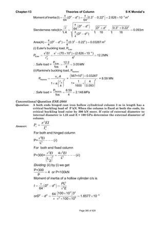
![Chapter-13 Theories of Column S K Mondal’s
Conventional Question AMIE-1996
Question: A piston rod of steam engine 80 cm long in subjected to a maximum load of 60
kN. Determine the diameter of the rod using Rankine's formula with
permissible compressive stress of 100 N/mm2. Take constant in Rankine's
formula as
1
7500
for hinged ends. The rod may be assumed partially fixed
with length coefficient of 0·6.
Answer: Given: 3 2
cl 80 cm 800mm ;P 60kN 60 10 N, 100N / mm ;σ= = = = × =
1
a for hinged ends; length coefficient 0.6
7500
= =
To find diameter of the rod, d:
Use Rankine’s formula
c
2
e
A
P
l
1 a
k
σ
=
⎛ ⎞
+ ⎜ ⎟
⎝ ⎠
eHere l 0.6l 0.6 800 480 mm [ length coefficient 0.6]= = × = =∵
4
2
d
I d64k
A 4d
4
π
π
= = =
2
3
2
100 d
4
60 10
1 480
1
7500 d / 4
π⎛ ⎞
× ⎜ ⎟
⎝ ⎠∴ × =
⎡ ⎤
+ ⎢ ⎥
⎣ ⎦
Solving the above equation we get the value of ‘d’
Note: Unit of d comes out from the equation will be mm as we put the equivalent
length in mm.
=or d 33.23mm
Conventional Question ESE-2005
Question: A hollow cylinder CI column, 3 m long its internal and external diameters as
80 mm and 100 mm respectively. Calculate the safe load using Rankine
formula: if
(i) Both ends are hinged and
(ii) Both ends are fixed.
Take crushing strength of material as 600
2
/N mm , Rankine constant 1/1600
and factor of safety = 3.
Answer:
π 4 4 4 6 4
Moment of Inertia (I)= (0.1 0.08 ) 2.898 10
64
m m−
− = ×
4
4 5
D D
1.25 or d =
d 1.25-5
1
D 1 1.8577 10
1.25
D=0.0749 m = 74.9 mm
given
or
or
−
=
⎡ ⎤⎛ ⎞⎢ ⎥⎟⎜− = ×⎟⎜⎢ ⎥⎟⎜⎝ ⎠⎢ ⎥⎣ ⎦
Page 381 of 429](https://image.slidesharecdn.com/strengthofmaterialsbyskmondal-130102103545-phpapp02-150924095946-lva1-app6891/85/Strengthofmaterialsbyskmondal-130102103545-phpapp02-381-320.jpg)
![C
C
Q
A
Chapter-13
Convention
Question:
Answer:
Area( )
Radius of
=
1
Rankine
A
P
=
(i)
=2
Safe load
(ii) For bo
RankineP
loadSafe
nal Questi
A slender
free end.
maximum
exceed th
Above figu
and eccent
Let y be th
deflection a
The bendin
(
π
σ
2
2
0.1
4
f gyration (
.
;c
e
A
a
k
= −
⎛ ⎞⎟⎜+ ⎟⎜ ⎟⎜⎝ ⎠
(600
Rank
10
=
1
1
2.61026kN
P
d (P)=
FOS
×
⎛
⎜+⎜⎜⎝
(
oth end fix
600
1
e
×
=
+
RankP
d (P)=
FOS
ion AMIE-
column is
Working
m length of
he eccentric
ure shows a
ric load P is
he deflection
at A.
ng moment a
Theorie
)2
0.08 2
I
(k) =
A
[ = eque
− =
=
) (6
ine
2.827
1 3
600 0.0
N
2612
S 3
×
⎞ ⎛⎟ ⎜×⎟ ⎜⎟ ⎜⎠ ⎝
=
)
e
6
xed,
10 (2.8
1
1600 0
=
×
⎛
⎜+ ×⎜⎜⎝
kine 714.8
S 3
=
-1997
built-in at
from the
f column su
city of load
slender colu
applied at t
n at any sect
at the sectio
es of Colum
2.8274 10
2.898
2.8274
uivalent len
×
×
×
)3
2
4 10
;
3
032
6
87.09
−
×
⎞⎟⎟⎟⎠
=
3
2
1.5
2
274 10
1.5
0.032
m
−
=
×
⎞⎟⎟⎟⎠
8
238.27=
t one end a
first prin
uch that th
ding.
umn of lengt
the free end
tion XX dist
n XX is give
mn
3 2
6
3
0
10
0.
10
ngth]
m−
−
−
×
=
×
[ = l = 3e
kN
)
714.8k=
7kN
and an ecce
nciples fin
he deflectio
th ‘I’. The co
A.
tant x from
en by
.032m
m for both
kN
entric load
nd the exp
on of the fr
olumn is bu
the fixed en
S K Mo
h end hing
is applied
pression fo
ree end do
ilt in at one
nd B. Let δ
ondal’s
ed]
at the
or the
oes not
e end B
be the
Page 382 of 429](https://image.slidesharecdn.com/strengthofmaterialsbyskmondal-130102103545-phpapp02-150924095946-lva1-app6891/85/Strengthofmaterialsbyskmondal-130102103545-phpapp02-382-320.jpg)
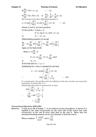
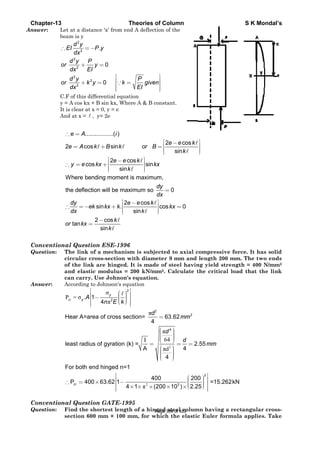
![Chapter-13 Theories of Column S K Mondal’s
yield strength and modulus of elasticity value for steel as 250 MPa and 200
GPa respectively.
Answer: Given: Cross-section, (= b x d) = 600 mm x 100 mm = 0.6 m x 0.1 m = 0.06 m2;
Yield strength =
2 12 2
250 250 / ; 200 200 10 /
P
MPa MN m E GPa N m
A
= = = = ×
3 3
5 40.6 0.1
Leastareamomentof Inertia, 5 10 m
12 12
bd
I −×
= = = ×
Length of the column,L :
( )
5
2 4 2
2
5 10
, 8.333 10
0.6 0.1
[ where area of cross-section, radius of gyration ]
I
Also k m
A
I AK A k
−
−×
= = = ×
×
= = =∵
2 2
2 2
From Euler's formula for column, we have
, cr
e
EI EI
Crushing load P
L L
π π
= =
( )
e
2 2
2
2
2
2 2
2
For bothendhinged type of column, = L
/
cr
cr
cr
L
EAk
or P
L
P EI
or Yield stress
A L
Ek
or L
P A
π
π
π
=
⎛ ⎞⎟⎜ =⎟⎜ ⎟⎟⎜⎝ ⎠
=
Substituting the value,we get
2 9
2
6
200 10 0.0008333
6.58
250 10
2.565
L
L m
π × × ×
= =
×
=
Conventional Question GATE-1993
Question: Determine the temperature rise necessary to induce buckling in a lm long
circular rod of diameter 40 mm shown in the Figure below. Assume the rod to
be pinned at its ends and the coefficient of thermal expansion as 6 0
20 10 / C−
×
. Assume uniform heating of the bar.
Answer: Letusassume the buckling load be'P'.
Page 385 of 429](https://image.slidesharecdn.com/strengthofmaterialsbyskmondal-130102103545-phpapp02-150924095946-lva1-app6891/85/Strengthofmaterialsbyskmondal-130102103545-phpapp02-385-320.jpg)
![Chapter-13 Theories of Column S K Mondal’s
( )
[ ]
2
e2
2
e2
. . , Where is the temperature rise.
.
.
,
where L =equivalentlength
. .
QL =L For bothendhinged
cr
e
L L t t
L
or t
L
PL L AE
Also L or P
AE L
EI
P
L
EI L A E
or
LL
δ
δ
δ
δ
π
π δ
= ∝
=
∝
= =
= −−−
=
( )
( ) ( )
2
2 2
2
42
0
2 4 6
. . . .
Substituting the values,we get
0.040
64Temperature rise 49.35
1 0.040 20 10
4
I
or L
LA
L I I
t
L LA L L A
t C
π
δ
δ π π
π
π
π −
=
= = =
∝ ∝ ∝
× ×
= =
× × × ×
So the rod will buckle when the temperature rises more than 49.35°C.
Page 386 of 429](https://image.slidesharecdn.com/strengthofmaterialsbyskmondal-130102103545-phpapp02-150924095946-lva1-app6891/85/Strengthofmaterialsbyskmondal-130102103545-phpapp02-386-320.jpg)
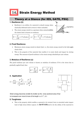
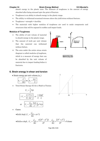
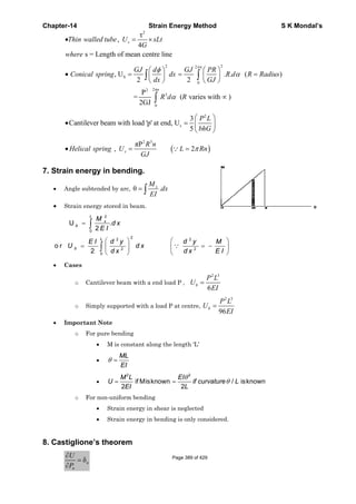
![Chapter-14 Strain Energy Method S K Mondal’s
1 ⎛ ⎞∂∂
= ⎜ ⎟
∂ ∂⎝ ⎠
∫ x
x
MU
M dx
p EI p
• Note:
o Strain energy, stored due to direct stress in 3 coordinates
21
(σ ) 2 σ σ
2
μ⎡ ⎤= −⎣ ⎦∑ ∑x x yU
E
o = =If σ σ σ ,in case of equal stress in 3 direction thenx y z
2 2
3σ σ
U= [1 2μ] (volume strain energy)
2 2E k
− =
Page 390 of 429](https://image.slidesharecdn.com/strengthofmaterialsbyskmondal-130102103545-phpapp02-150924095946-lva1-app6891/85/Strengthofmaterialsbyskmondal-130102103545-phpapp02-390-320.jpg)
![Chapter-14 Strain Energy Method S K Mondal’s
OBJECTIVE QUESTIONS (GATE, IES, IAS)
Previous 20-Years GATE Questions
Strain Energy or Resilience
GATE-1. The strain energy stored in the beam with flexural rigidity EI and loaded as
shown in the figure is: [GATE-2008]
(a)
2 3
3
P L
EI
(b)
2 3
2
3
P L
EI
(c)
2 3
4
3
P L
EI
(d)
2 3
8
3
P L
EI
GATE-1. Ans. (c)
4 3 42 2 2 2
0 0 3
L L L L
L L
M dx M dx M dx M dx
EI EI EI EI
= + +∫ ∫ ∫ ∫
3 42 2 2 2
0 0 3
32 2 2 3
0
2 By symmetry
( ) ( ) 4
2
3
L L L L
L L
L L
L
M dx M dx M dx M dx
EI EI EI EI
Px dx PL dx P L
EI EI EI
⎡ ⎤
⎢ ⎥= + =⎢ ⎥
⎢ ⎥⎣ ⎦
= + =
∫ ∫ ∫ ∫
∫ ∫
GATE-2.
3
3
PL
EI
is the deflection under the load P of a cantilever beam [length L, modulus
of elasticity, E, moment of inertia-I]. The strain energy due to bending is:
[GATE-1993]
2 3 2 3 2 3 2 3
( ) ( ) ( ) ( )
3 6 4 48
P L P L P L P L
a b c d
EI EI EI EI
GATE-2. Ans. (b) We may do it taking average
Strain energy = Average force x displacement =
3
2 3
⎛ ⎞
× =⎜ ⎟
⎝ ⎠
P PL
EI
2 3
6
P L
EI
Alternative method: In a funny way you may use Castiglione’s theorem,
U
P
δ
∂
=
∂
. Then
U
P
δ
∂
=
∂
3
3
PL
EI
= or
3
3
PL
U U P
EI
= ∂ = ∂∫ ∫ Partially integrating with respect to P we get
2 3
P L
U
6EI
=
Page 391 of 429](https://image.slidesharecdn.com/strengthofmaterialsbyskmondal-130102103545-phpapp02-150924095946-lva1-app6891/85/Strengthofmaterialsbyskmondal-130102103545-phpapp02-391-320.jpg)
![C
G
G
G
G
T
G
G
S
I
I
I
Chapter-14
GATE-3. T
m
r
a
(a
(b
(c
(d
GATE-3. An
=
T
=
=
GATE-4. A
s
r
in
(a
GATE-4. A
U
o
Toughn
GATE-5. T
t
(a
GATE-5. An
Strain E
ES-1. W
g
(a
W
ES-1. Ans.
ES-2. A
b
Y
The stress
material i
resilience
are respect
a) 28 × 104,
b) 28 × 104,
c) 14 × 104, 9
d) 76 × 104
ns. (c) Resili
=
1
0.004
2
× ×
Toughness =
= 4
14 10 7× +
4
90 10= × Nm
A square ba
same bar is
ratio of the
n the first
a) 16
Ans. (d) =1U
= =
= =
2 3
2
2
2
2
1
W L
U
6EI
U 4L
or
U a
ness
The total ar
o failure u
a) Ductility
ns. (d)
Prev
Energy
What is the
gradually a
a)
E
V
σ
Where, E = M
(d) Strain
A bar havin
both tensil
Young's mo
s-strain b
is shown
and tough
ively
76 × 104
48 × 104
90 × 104
ience = area
6
70 10 14× =
area under
(6
70 10 0.0× ×
m/m3
ar of side 4
s then used
e strain ene
case, is:
⎛ ⎞
⎜ ⎟
⎝ ⎠= =
2
W
AL
A
2E
=
⎛ ⎞
⎜ ⎟
⎝ ⎠
⎛ ⎞
= × ⎜ ⎟
⎝ ⎠
2 3
4
2
W L
1
6E a
12
100
4
4
rea under
nder tensio
(b) U
vious 2
y or Re
e strain en
applied load
Modulus of e
Energy =
1
2
ng length
e force P
odulus, the
Strain En
behaviour
in figur
hness, in N
under this c
4
4 10× Nm/m
this curve u
)012 0.004−
4 cm and le
d as a canti
ergies, stor
(b) 400
=
2
W L
2AE
=
=
2 3
4
2W L
Ea
2500
the stress-
on is a mea
Ultimate stre
20-Ye
esilienc
nergy store
d?
(b)
2
E
V
σ
elasticity
2
. V
E
σ
×
L and uni
and torqu
internal st
nergy Meth
of a
re. Its
Nm/m3,
curve up to
m3
up to 0.012 s
(
1
0.012
2
+ ×
ength 100 cm
ilever beam
red in the
-strain curv
asure of
ength
ars IE
ce
ed in a bod
form cross
ue T. If G
train energ
hod
0.004 strain
strain
) (0.004 1− ×
m is subjec
m and subje
bar in the
(c) 1000
ve of a mil
(c) Stiffn
ES Que
dy of volum
(c)
2
V
E
σ
s-section w
is the she
gy stored in
n
)20 70 10− ×
cted to an a
ected to all
second ca
ld steel spe
ness
estion
me V with
with area A
ear modul
n the bar is
S K Mo
[GATE
6
0 Nm/m3
axial load P
l end load P
se to that
[GATE
(d) 2500
ecimen test
[GATE
(d) Tough
ns
stress σ d
[IES
(d)
2
2
V
E
σ
A is subjec
us and E
s: [IES
ondal’s
E-2000]
P. The
P. The
stored
E-1998]
ted up
E-2002]
hness
due to
S-2006]
cted to
is the
S-2003]
Page 392 of 429](https://image.slidesharecdn.com/strengthofmaterialsbyskmondal-130102103545-phpapp02-150924095946-lva1-app6891/85/Strengthofmaterialsbyskmondal-130102103545-phpapp02-392-320.jpg)
![Chapter-14 Strain Energy Method S K Mondal’s
(a)
2 2
2
T L P L
GJ AE
+ (b)
2 2
2
T L P L
GJ AE
+ (c)
2 2
2 2
T L P L
GJ AE
+ (d)
2 2
T L P L
GJ AE
+
IES-2. Ans. (c)
1 1 1 1
Internal strain energy = P + P +
2 2 2 2
PL TL
T T
AE GJ
δ θ =
IES-3. Strain energy stored in a body of volume V subjected to uniform stress s is:
[IES-2002]
(a) s E / V (b) sE2/ V (c) sV2/E (d) s2V/2E
IES-3. Ans. (d)
IES-4. A bar of length L and of uniform cross-sectional area A and second moment of
area ‘I’ is subjected to a pull P. If Young's modulus of elasticity of the bar
material is E, the expression for strain energy stored in the bar will be:
[IES-1999]
2 2 2 2
P L PL PL P L
(a) (b) (c) (d)
2AE 2EI AE AE
IES-4. Ans. (a) ( )
2
1 1
Strain energy x stress x strain x volume= .
2 2 2
P P L PL
AL
A A E AE
⎛ ⎞ ⎛ ⎞
= × × × =⎜ ⎟ ⎜ ⎟
⎝ ⎠ ⎝ ⎠
IES-5. Which one of the following gives the correct expression for strain energy
stored in a beam of length L and of uniform cross-section having moment of
inertia ‘I’ and subjected to constant bending moment M? [IES-1997]
( ) ( ) ( ) ( )
2 2
a b c d
2 2
ML ML M L M L
EI EI EI EI
IES-5. Ans. (d)
IES-6. A steel specimen 150
2
mm in cross-section stretches by 0·05 mm over a 50 mm
gauge length under an axial load of 30 kN. What is the strain energy stored in
the specimen? (Take E = 200 GPa) [IES-2009]
(a) 0.75 N-m (b) 1.00 N-m (c) 1.50 N-m (d) 3.00 N-m
IES-6. Ans. (a) Strain Energy stored in the specimen
( ) −
−
× ×⎛ ⎞
= δ = = = =⎜ ⎟
× × × ×⎝ ⎠
2 32
6 9
30000 50 101 1 PL P L
P P 0.75 N-m
2 2 AE 2AE 2 150 10 200 10
IES-7. What is the expression for the strain energy due to bending of a cantilever
beam (length L. modulus of elasticity E and moment of inertia I)? [IES-2009]
(a)
2 3
3
P L
EI
(b)
2 3
6
P L
EI
(c)
2 3
4
P L
EI
(d)
2 3
48
P L
EI
IES-7. Ans. (b) Strain Energy Stored
⎛ ⎞
= = =⎜ ⎟
⎝ ⎠
∫
L
L 2 2 3 2 3
0 0
(Px) dx P x P L
2E 2EI 3 6EI
IES-8. The property by which an amount of energy is absorbed by a material without
plastic deformation, is called: [IES-2000]
(a) Toughness (b) Impact strength (c) Ductility (d) Resilience
IES-8. Ans. (d)
IES-9. 30 C 8 steel has its yield strength of 400 N/mm2 and modulus of elasticity of 2 ×
105 MPa. Assuming the material to obey Hooke's law up to yielding, what is its
proof resilience? [IES-2006]
(a) 0·8 N/mm2 (b) 0.4 N/mm2 (c) 0·6 N/mm2 (d) 0·7 N/mm2
IES-9. Ans. (b) Proof resilience ( ) ( )
2
2
2
p 5
4001 1
R . 0.4N / mm
2 E 2 2 10
σ
= = × =
×Page 393 of 429](https://image.slidesharecdn.com/strengthofmaterialsbyskmondal-130102103545-phpapp02-150924095946-lva1-app6891/85/Strengthofmaterialsbyskmondal-130102103545-phpapp02-393-320.jpg)
![Chapter-14 Strain Energy Method S K Mondal’s
Toughness
IES-10. Toughness for mild steel under uni-axial tensile loading is given by the shaded
portion of the stress-strain diagram as shown in [IES-2003]
IES-10. Ans. (d) Toughness of material is the total area under stress-strain curve.
Previous 20-Years IAS Questions
Strain Energy or Resilience
IAS-1. Total strain energy stored in a simply supported beam of span, 'L' and flexural
rigidity 'EI 'subjected to a concentrated load 'W' at the centre is equal to:
[IAS-1995]
(a)
2 3
40
W L
EI
(b)
2 3
60
W L
EI
(c)
2 3
96
W L
EI
(d)
2 3
240
W L
EI
IAS-1. Ans. (c) Strain energy =
2L L/2 L/22 2 2 3
0 0 0
M dx M dx 1 Wx W L
2 dx
2EI 2EI EI 2 96EI
⎛ ⎞
= × = × =⎜ ⎟
⎝ ⎠
∫ ∫ ∫
Alternative method: In a funny way you may use Castiglione’s theorem,
U U
P W
δ
∂ ∂
= =
∂ ∂
We know that
3
48
WL
EI
δ = for simply supported beam in concentrated load at mid span.
Then
U U
P W
δ
∂ ∂
= =
∂ ∂
3
48
WL
EI
= or
3
48
WL
U U W
EI
= ∂ = ∂∫ ∫ partially integrating with
respect to W we get
2 3
W L
U
96EI
=
IAS-2. If the cross-section of a member is subjected to a uniform shear stress of
intensity 'q' then the strain energy stored per unit volume is equal to (G =
modulus of rigidity). [IAS-1994]
(a) 2q2/G (b) 2G / q2 (c) q2 /2G (d) G/2 q2
IAS-2. Ans. (c)
IAS-3. The strain energy stored in the beam with flexural rigidity EI and loaded as
shown in the figure is: [GATE-2008]
Page 394 of 429](https://image.slidesharecdn.com/strengthofmaterialsbyskmondal-130102103545-phpapp02-150924095946-lva1-app6891/85/Strengthofmaterialsbyskmondal-130102103545-phpapp02-394-320.jpg)
![Chapter-14 Strain Energy Method S K Mondal’s
(a)
2 3
3
P L
EI
(b)
2 3
2
3
P L
EI
(c)
2 3
4
3
P L
EI
(d)
2 3
8
3
P L
EI
IAS-3. Ans. (c)
4 3 42 2 2 2
0 0 3
L L L L
L L
M dx M dx M dx M dx
EI EI EI EI
= + +∫ ∫ ∫ ∫
3 42 2 2 2
0 0 3
32 2 2 3
0
2 By symmetry
( ) ( ) 4
2
3
L L L L
L L
L L
L
M dx M dx M dx M dx
EI EI EI EI
Px dx PL dx P L
EI EI EI
⎡ ⎤
⎢ ⎥= + =⎢ ⎥
⎢ ⎥⎣ ⎦
= + =
∫ ∫ ∫ ∫
∫ ∫
IAS-4. Which one of the following statements is correct? [IAS-2004]
The work done in stretching an elastic string varies
(a) As the square of the extension (b) As the square root of the extension
(c) Linearly with the extension (d) As the cube root of the extension
IAS-4. Ans. (a)
( )
2
2
2
2
1 1
2 2 2
l
E E
E L
δσ
⎡ ⎤
⎢ ⎥= ∈ = ⎢ ⎥
⎢ ⎥⎣ ⎦
Toughness
IAS-5. Match List-I with List-II and select the correct answer using the codes given
below the lists: [IAS-1996]
List-I (Mechanical properties) List-II (Meaning of properties)
A. Ductility 1. Resistance to indentation
B. Hardness 2. Ability to absorb energy during plastic
C. Malleability deformation
D. Toughness 3. Percentage of elongation
4. Ability to be rolled into flat product
Codes: A B C D A B C D
(a) 1 4 3 2 (b) 3 2 4 1
(c) 2 3 4 1 (d) 3 1 4 2
IAS-5. Ans. (d)
IAS-6. Match List-I (Material properties) with List-II (Technical
definition/requirement) and select the correct answer using the codes below
the lists: [IAS-1999]
List-I List-II
A. Hardness 1. Percentage of elongation
B. Toughness 2. Resistance to indentation
C. Malleability 3. Ability to absorb energy during plastic deformation
D. Ductility 4. Ability to be rolled into plates
Codes: A B C D A B C D
(a) 3 2 1 4 (b) 2 3 4 1
(c) 2 4 3 1 (d) 1 3 4 2
IAS-6. Ans. (b)
IAS-7. A truck weighing 150 kN and travelling at 2m/sec impacts which a buffer
spring which compresses 1.25cm per 10 kN. The maximum compression of the
spring is: [IAS-1995]Page 395 of 429](https://image.slidesharecdn.com/strengthofmaterialsbyskmondal-130102103545-phpapp02-150924095946-lva1-app6891/85/Strengthofmaterialsbyskmondal-130102103545-phpapp02-395-320.jpg)
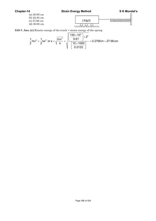
![Chapter-14 Strain Energy Method S K Mondal’s
Previous Conventional Questions with Answers
Conventional Question IES 2009
Q. A close coiled helical spring made of wire diameter d has mean coil radius R,
number of turns n and modulus of rigidity G. The spring is subjected to an
axial compression W.
(1) Write the expression for the stiffness of the spring.
(2) What is the magnitude of the maximum shear stress induced in the spring
wire neglecting the curvature effect? [2 Marks]
Ans. (1) Spring stiffness, K =
(2) Maximum shear stress,
Conventional Question IES 2010
Q. A semicircular steel ring of mean radius 300 mm is suspended vertically with
the top end fixed as shown in the above figure and carries a vertical load of 200
N at the lowest point.
Calculate the vertical deflection of the lower end if the ring is of rectangular
cross- section 20 mm thick and 30 mm wide.
Value of Elastic modulus is
5 2
2 10 N/mm× .
Influence of circumferential and shearing forces may be neglected.
[10 Marks]
Ans. Load applied, F = 200 N
Mean Radius, R = 300 mm
Elastic modules, E =
5 2
2 10 N/mm×
I = Inertia of moment of cross – section
3
bd
I b = 20 mm
12
=
( )
3
4
d = 30 mm
20 30
= = 45,000 mm
12
×
⇒ Influence of circumferential and shearing force are neglected strain energy at the section.
4
3
W Gd
X 8nD
=
3
8WD
d
τ =
π
Page 397 of 429](https://image.slidesharecdn.com/strengthofmaterialsbyskmondal-130102103545-phpapp02-150924095946-lva1-app6891/85/Strengthofmaterialsbyskmondal-130102103545-phpapp02-397-320.jpg)
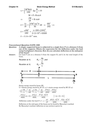
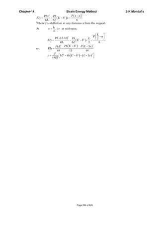
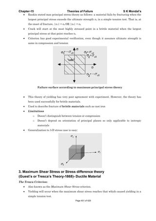
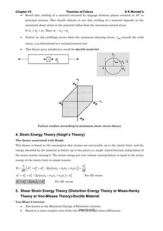
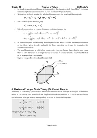
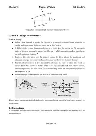
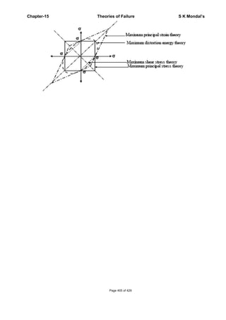
![Chapter-15 Theories of Failure S K Mondal’s
OBJECTIVE QUESTIONS (GATE, IES, IAS)
Previous 20-Years GATE Questions
Maximum Shear stress or Stress Difference Theory
GATE-1. Match 4 correct pairs between list I and List II for the questions [GATE-1994]
List-I List-II
(a) Hooke's law 1. Planetary motion
(b) St. Venant's law 2. Conservation Energy
(c) Kepler's laws 3. Elasticity
(d) Tresca's criterion 4. Plasticity
(e) Coulomb's laws 5. Fracture
(f) Griffith's law 6. Inertia
GATE-1. Ans. (a) - 3, (c) -1, (d) -5, (e) -2
St. Venant's law: Maximum principal strain theory
GATE-2. Which theory of failure will you use for aluminium components under steady
loading? [GATE-1999]
(a) Principal stress theory (b) Principal strain theory
(c) Strain energy theory (d) Maximum shear stress theory
GATE-2. Ans. (d) Aluminium is a ductile material so use maximum shear stress theory
Shear Strain Energy Theory (Distortion energy theory)
GATE-3. According to Von-Mises' distortion energy theory, the distortion energy under
three dimensional stress state is represented by [GATE-2006]
GATE-3. Ans. (c)
( ) ( ) ( ){ }2 2 2
s 1 2 2 3 3 1
1
V Where E 2G(1 ) simplifyand getresult.
12G
σ σ σ σ σ σ μ= − + − + − = +
GATE-4. A small element at the critical section of a component is in a bi-axial state of
stress with the two principal stresses being 360 MPa and 140 MPa. The
maximum working stress according to Distortion Energy Theory is:
[GATE-1997]
(a) 220 MPa (b) 110 MPa (c) 314 MPa (d) 330 MPa
GATE-4. Ans. (c) According to distortion energy theory if maximum stress (σt) then
2 2 2
t 1 2 1 2
2 2 2
t
t
or
or 360 140 360 140
or 314 MPa
σ σ σ σ σ
σ
σ
= + −
= + − ×
=
Page 406 of 429](https://image.slidesharecdn.com/strengthofmaterialsbyskmondal-130102103545-phpapp02-150924095946-lva1-app6891/85/Strengthofmaterialsbyskmondal-130102103545-phpapp02-406-320.jpg)
![Chapter-
Maxim
IES-1.
IES-1. An
IES-2.
IES-2. An
IES-3.
IES-3. An
IES-4.
IES-4. An
IES-5.
IES-5. An
Maxim
IES-6.
-15
Pre
mum P
Match Li
Direct S
answer u
List-I
A. Maxim
B. Maxim
C. Maxim
D. Maxim
Codes:
(a)
(c)
ns. (d)
From a t
a factor
the perm
(a) 50 N/m
ns. (d) For p
A circul
twisting
theory, t
theory, t
( )
1
a
5
ns. (c) σ
π
=
Therefor
A transm
of
(a) Maxim
(b) Maxim
(c) Maxim
(d) Fatigu
ns. (a)
Design o
(a) Guest'
ns. (b) Ran
brittle ma
mum S
Which on
or Tresca
evious
Principa
ist-I (Theor
Stress at Y
using the c
mum shear st
mum distorti
mum principa
mum principa
A B
1 2
1 3
tension tes
of safety o
missible str
mm2
pure shear τ
ar solid sh
moment o
the direct
the shear st
(
(3
16
M M
dπ
+
M
e
M
σ
τ
+
=
mission sha
mum normal
mum shear s
mum normal
ue strength
of shafts ma
's theory (b
nkine's theor
aterials.
Shear s
ne of the fo
a criterion
Theo
s 20-Y
al Stres
ry of Failu
Yield Cond
ode given b
tress theory
on energy th
al stress the
al strain the
C
4
4
st, the yield
f 2 and app
ess in the s
(b) 57.7 N
xτ σ= ±
haft is sub
of 300 kNm
stress is
tress is τ . T
( )
3
b
9
)2 2
M T a+
2 2
2 2
M T 4
M T
+
=
+
aft subjecte
l stress theo
stress theory
stress and m
ade of britt
b) Rankine’s
ry or maxim
stress o
ollowing fig
n?
ories of Fa
Years I
ss The
re) with Li
ition for S
below the L
y
heory
eory
eory
D
3 (b
2 (d
d strength
plying max
steel shaft
N/mm2
bjected to
m. On the
σ and acc
The ratio σ
(
(3
16
nd
d
τ
π
=
2 2
2 2
4 4 3
4 3
+ +
+
ed to bendi
ry
y
maximum sh
tle materia
theory (c
mum princip
or Stre
gures repre
ailure
IES Qu
eory
ist-II (Pred
Steel Speci
Lists:
A
b) 4
d) 4
of steel is
ximum prin
subjected t
(c) 86.6
a bending
basis of th
cording to
σ/ τ is:
( )
9
c
5
( )2 2
M T+
2
9
5
=
ing loads m
hear stress t
als is based
c) St. Venant
ple stress th
ss Diff
esents the
uestio
dicted Ratio
imen) and
List-II
1. 1·0
2. 0·577
3. 0·62
4. 0·50
B C
3 1
2 1
found to b
ncipal stres
to torque w
. N/mm2
g moment
he maximu
o the max
( )
1
d
6
must be de
theories
on
t's theory (d)
heory is mos
ference
maximum
S K
ons
o of Shear
select the
[I
C D
2
3
e 200 N/mm
ss theory o
will be: [I
(d) 100
of 400 kN
um princip
imum shea
[I
1
6
signed on
[I
[I
) Von Mises
st commonly
e Theo
shear stre
[I
Mondal’s
Stress to
e correct
IES-2006]
m2. Using
of failure,
IES-2000]
N/mm2
Nm and a
pal stress
ar stress
IES-2000]
the basis
IES-1996]
IES-1993]
theory
y used for
ry
ss theory
IES-1999]
Page 407 of 429](https://image.slidesharecdn.com/strengthofmaterialsbyskmondal-130102103545-phpapp02-150924095946-lva1-app6891/85/Strengthofmaterialsbyskmondal-130102103545-phpapp02-407-320.jpg)
![Chapter-15 Theories of Failure S K Mondal’s
IES-6. Ans. (b)
IES-7. According to the maximum shear stress theory of failure, permissible twisting
moment in a circular shaft is 'T'. The permissible twisting moment will the
same shaft as per the maximum principal stress theory of failure will be:
[IES-1998: ISRO-2008]
(a) T/2 (b) T (c) 2T (d) 2T
IES-7. Ans. (d)
yt
3
16T
Given principalstressesfor only thisshear stressare
2d
σ
τ
π
= =
( )
σ τ τ
σ σ σ
π
= = ±
= =
2
1,2
1 2 yt 3
maximum principal stress theory of failuregives
16 2T
max[ , ]
d
IES-8. Permissible bending moment in a circular shaft under pure bending is M
according to maximum principal stress theory of failure. According to
maximum shear stress theory of failure, the permissible bending moment in
the same shaft is: [IES-1995]
(a) 1/2 M (b) M (c) 2 M (d) 2M
IES-8. Ans. (b) ( ) ( )2 2 2 2
3 3
16 16
M M T and M T
d d
σ τ
π π
= + + = + put T = 0
3
yt
yt 3 3 3
32M
32M 16M 16Md
or and ThereforeM M
2 2d d d
σ π
σ τ
π π π
⎛ ⎞
⎜ ⎟′ ⎝ ⎠ ′= = = = = =
IES-9. A rod having cross-sectional area 100 x 10- 6 m2 is subjected to a tensile load.
Based on the Tresca failure criterion, if the uniaxial yield stress of the material
is 200 MPa, the failure load is: [IES-2001]
(a) 10 kN (b) 20 kN (c) 100 kN (d) 200 kN
IES-9. Ans. (b) Tresca failure criterion is maximum shear stress theory.
yt
max
P sin2 P
Weknow that, or
A 2 2A 2
σθ
τ τ= = = or ytP Aσ= ×
IES-10. A cold roller steel shaft is designed on the basis of maximum shear stress
theory. The principal stresses induced at its critical section are 60 MPa and - 60
MPa respectively. If the yield stress for the shaft material is 360 MPa, the
factor of safety of the design is: [IES-2002]
(a) 2 (b) 3 (c) 4 (d) 6
IES-10. Ans. (b)
IES-11. A shaft is subjected to a maximum bending stress of 80 N/mm2 and maximum
shearing stress equal to 30 N/mm2 at a particular section. If the yield point in
tension of the material is 280 N/mm2, and the maximum shear stress theory of
failure is used, then the factor of safety obtained will be: [IES-1994]
(a) 2.5 (b) 2.8 (c) 3.0 (d) 3.5
IES-11. Ans. (b) Maximum shear stress =
2
2 280 0
30 50 N/mm
2
−⎛ ⎞
+ =⎜ ⎟
⎝ ⎠
According to maximum shear stress theory,
280
; . . 2.8
2 2 50
y
F S
σ
τ = ∴ = =
×
IES-12. For a two-dimensional state stress ( 1 2 1 2, 0, 0σ σ σ σ> > < ) the designed values
are most conservative if which one of the following failure theories were used?
[IES-1998]
(a) Maximum principal strain theory (b) Maximum distortion energy theory
(c) Maximum shear stress theory (d) Maximum principal stress theory
IES-12. Ans. (c)
Page 408 of 429](https://image.slidesharecdn.com/strengthofmaterialsbyskmondal-130102103545-phpapp02-150924095946-lva1-app6891/85/Strengthofmaterialsbyskmondal-130102103545-phpapp02-408-320.jpg)
![Chapter-15 Theories of Failure S K Mondal’s
Graphical comparison of different failure theories
Above diagram shows that 1 20, 0σ σ> < will occur at 4th quadrant and most
conservative design will be maximum shear stress theory.
Shear Strain Energy Theory (Distortion energy theory)
IES-13. Who postulated the maximum distortion energy theory? [IES-2008]
(a) Tresca (b) Rankine (c) St. Venant (d) Mises-Henky
IES-13. Ans. (d)
IES-14. Who postulated the maximum distortion energy theory? [IES-2008]
(a) Tresca (b) Rankine (c) St. Venant (d) Mises-Henky
IES-14. Ans. (d)
Maximum shear stress theory → Tresca
Maximum principal stress theory → Rankine
Maximum principal strain theory → St. Venant
Maximum shear strain energy theory → Mises – Henky
IES-15. The maximum distortion energy theory of failure is suitable to predict the
failure of which one of the following types of materials? [IES-2004]
(a) Brittle materials (b) Ductile materials (c) Plastics (d) Composite materials
IES-15. Ans. (b)
IES-16. If σy is the yield strength of a particular material, then the distortion energy
theory is expressed as [IES-1994]
(a) ( ) ( ) ( )
2 2 2 2
1 2 2 3 3 1 2 yσ σ σ σ σ σ σ− + − + − =
(b) ( )2 2 2 2
1 2 3 1 2 2 3 3 12 ( ) yσ σ σ μ σ σ σ σ σ σ σ− + − + + =
(c) ( ) ( ) ( )
2 2 2 2
1 2 2 3 3 1 3 yσ σ σ σ σ σ σ− + − + − =
(d) ( )( ) ( )
2 2
1 2 31 2 2 1 yμ σ σ σ μ σ− + + = +
IES-16. Ans. (a)
IES-17. If a shaft made from ductile material is subjected to combined bending and
twisting moments, calculations based on which one of the following failure
theories would give the most conservative value? [IES-1996]
(a) Maximum principal stress theory (b) Maximum shear stress theory.
(d Maximum strain energy theory (d) Maximum distortion energy theory.
IES-17. Ans. (b)
Page 409 of 429](https://image.slidesharecdn.com/strengthofmaterialsbyskmondal-130102103545-phpapp02-150924095946-lva1-app6891/85/Strengthofmaterialsbyskmondal-130102103545-phpapp02-409-320.jpg)
![Chapter-15 Theories of Failure S K Mondal’s
Maximum Principal Strain Theory
IES-18. Match List-I (Failure theories) with List-II (Figures representing boundaries of
these theories) and select the correct answer using the codes given below the
Lists: [IES-1997]
List-I List-II
A. Maximum principal stress
theory
B. Maximum shear stress theory
C. Maximum octahedral stress
theory
D. Maximum shear strain
energy theory
Code: A B C D A B C D
(a) 2 1 3 4 (b) 2 4 3 1
(c) 4 2 3 1 (d) 2 4 1 3
IES-18. Ans. (d)
Previous 20-Years IAS Questions
Maximum Principal Stress Theory
IAS-1. For 1 2σ σ≠ and σ3 = 0, what is the physical boundary for Rankine failure
theory? [IAS-2004]
(a) A rectangle (b) An ellipse (c) A square (d) A parabola
Page 410 of 429](https://image.slidesharecdn.com/strengthofmaterialsbyskmondal-130102103545-phpapp02-150924095946-lva1-app6891/85/Strengthofmaterialsbyskmondal-130102103545-phpapp02-410-320.jpg)
![Chapter-15 Theories of Failure S K Mondal’s
IAS-1. Ans. (c) Rankine failure theory or
Maximum principle stress theory.
Shear Strain Energy Theory (Distortion energy theory)
IAS-2. Consider the following statements: [IAS-2007]
1. Experiments have shown that the distortion-energy theory gives an
accurate prediction about failure of a ductile component than any other
theory of failure.
2. According to the distortion-energy theory, the yield strength in shear is less
than the yield strength in tension.
Which of the statements given above is/are correct?
(a) 1 only (b) 2 only (c) Both 1 and 2 (d) Neither 1 nor 2
IAS-2. Ans. (c) 0.577
3
y
y y
σ
τ σ= =
IAS-3. Consider the following statements: [IAS-2003]
1. Distortion-energy theory is in better agreement for predicting the failure of
ductile materials.
2. Maximum normal stress theory gives good prediction for the failure of
brittle materials.
3. Module of elasticity in tension and compression are assumed to be different
stress analysis of curved beams.
Which of these statements is/are correct?
(a) 1, 2 and 3 (b) 1 and 2 (c) 3 only (d) 1 and 3
IAS-3. Ans. (b)
IAS-4. Which one of the following graphs represents Mises yield criterion? [IAS-
1996]
IAS-4. Ans. (d)
Maximum Principal Strain Theory
IAS-5. Given that the principal stresses 1 2 3σ σ σ> > and σe is the elastic limit stress in
simple tension; which one of the following must be satisfied such that the
elastic failure does not occur in accordance with the maximum principal strain
theory? [IAS-2004]
(a) 31 2e
E E E E
σ σσ σ
μ μ
⎛ ⎞
< − −⎜ ⎟
⎝ ⎠
(b) 31 2e
E E E E
σ σσ σ
μ μ
⎛ ⎞
> − −⎜ ⎟
⎝ ⎠
Page 411 of 429](https://image.slidesharecdn.com/strengthofmaterialsbyskmondal-130102103545-phpapp02-150924095946-lva1-app6891/85/Strengthofmaterialsbyskmondal-130102103545-phpapp02-411-320.jpg)
![Chapter-15 Theories of Failure S K Mondal’s
Previous Conventional Questions with Answers
Conventional Question ESE-2010
Q. The stress state at a point in a body is plane with
2 2
1 2σ 60N / mm & σ 36N / mm= = −
If the allowable stress for the material in simple tension or compression is
100 N/mm2 calculate the value of factor of safety with each of the following
criteria for failure
(i) Max Stress Criteria
(ii) Max Shear Stress Criteria
(iii) Max strain criteria
(iv) Max Distortion energy criteria [10 Marks]
Ans. The stress at a point in a body is plane
Allowable stress for the material in simple tension or compression is 100 N/mm2
Find out factor of safety for
(i) Maximum stress Criteria : - In this failure point occurs when max principal stress
reaches the limiting strength of material.
Therefore. Let F.S factor of safety
( )
1
2
2
allowable
F.S
100 N / mm
F.S 1.67 Ans.
60 N / mm
σ
σ =
= =
(ii) Maximum Shear stress criteria : - According to this failure point occurs at a point in a
member when maximum shear stress reaches to shear at yield point
σ
γ = σ =
σ − σ +
γ = = = =
=
×
= = =
×
=
yt 2
max yt
21 2
max
100 N / mm
2 F.S
60 36 96
48 N / mm
2 2 2
100
48
2 F.S
100 100
F.S 1.042
2 48 96
F.S 1.042 Ans.
(iii) Maximum Strain Criteria ! – In this failure point occurs at a point in a member when
maximum strain in a bi – axial stress system reaches the limiting value of strain (i.e
strain at yield point)
( )
2
2 2 allowable
1 2 1 2
σ
σ σ 2μσ σ
FOS
FOS 1.27
μ 0.3assume
⎛ ⎞
+ − = ⎜ ⎟
⎝ ⎠
=
=
(iv) Maximum Distortion energy criteria ! – In this failure point occurs at a point in a
member when distortion strain energy per unit volume in a bi – axial system reaches the
limiting distortion strain energy at the of yield
2 2
1 260 N / mm 36 N / mmσ = σ = −
Page 413 of 429](https://image.slidesharecdn.com/strengthofmaterialsbyskmondal-130102103545-phpapp02-150924095946-lva1-app6891/85/Strengthofmaterialsbyskmondal-130102103545-phpapp02-413-320.jpg)
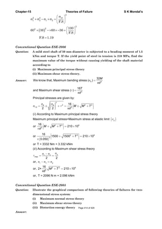
![Chapter-
Convent
Question
Answer:
Convent
Question
Answer:
Convent
Question
Answer:
-15
tional Que
n: State th
Accordin
per unit
volume
(σ σ1 −
tional Que
n: Derive
subject
princip
Accordin
per unit
volume
change
Substitu
At the t
The fail
In a 2-D
tional Que
n: A cube
(i) D
(ii) W
V
Yield st
estion ESE
he Von- Mi
ng to this t
t volume du
at the tensi
) (σ σ
2
2 2+ −
estion ESE
an expres
ted to a u
pal stress σ
ng to this t
t volume du
at the tensi
EV can be gi
uting strain
tensile yield
lure criterion
D situation if
estion GAT
of 5mm sid
etermine t
Will the cub
on-Mises th
trength of th
Theo
E-2004
ises's theor
theory yield
ue to applied
ile yield poin
) (σ σ
2
3 3
[sym
− +
E-2002
ssion for t
uniform str
3σ being ze
theory yield
ue to applied
ile yield poi
iven as
s in terms o
point, σ1 = σ
n is thus obt
f σ3 = 0, the
TE-1996
de is loade
the princip
be yield if
heory.
he material σ
ories of Fa
ry. Also giv
ing would o
d loads exce
nt. The failu
)σ σ
2
1 2
mbols has u
− =
he distorti
ress state,
ero.
ing would o
d loads exce
nt. Total str
of stresses th
σy , σ2 = σ3 =
tained by eq
criterion red
d as shown
pal stresses
the yield s
etσ = 70 MPa
ailure
ve the natur
occur when
eeds the dis
ure criterion
yσ2
usual mea
ion energy
given by
occur when
eeds the dis
rain energy
he distortion
0 which giv
quating Ed a
duces to
n in figure
s 1 2 3σ ,σ ,σ .
strength of
a = 70 MN/m
rally expre
total distor
tortion ener
is
ning]
y per unit
the 1σ and
total distor
tortion ener
ET and stra
n energy can
es
nd Edy , whi
below.
f the mater
m2 or 70 N/m
S K
ession.
rtion energy
rgy absorbed
volume fo
2d σ with t
rtion energy
rgy absorbed
ain energy f
n be given as
ich gives
rial is 70 M
mm2.
Mondal’s
y absorbed
d per unit
or a body
the third
y absorbed
d per unit
for volume
s
MPa? Use
Page 415 of 429](https://image.slidesharecdn.com/strengthofmaterialsbyskmondal-130102103545-phpapp02-150924095946-lva1-app6891/85/Strengthofmaterialsbyskmondal-130102103545-phpapp02-415-320.jpg)
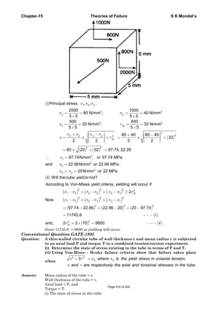
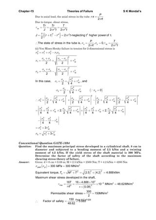


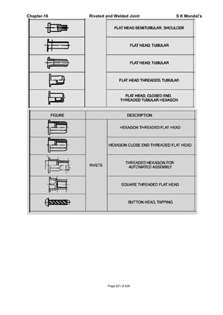
![Chapter-16 Riveted and Welded Joint S K Mondal’s
OBJECTIVE QUESTIONS (GATE, IES, IAS)
Previous 20-Years GATE Questions
Failure of riveted joint
GATE-1. Bolts in the flanged end of pressure vessel are usually pre-tensioned Indicate
which of the following statements is NOT TRUE? [GATE-1999]
(a) Pre-tensioning helps to seal the pressure vessel
(b) Pre-tensioning increases the fatigue life of the bolts
(c) Pre-tensioning reduces the maximum tensile stress in the bolts
(d) Pre-tensioning helps to reduce the effect of pressure pulsations in the pressure vessel
GATE-1. Ans. (c)
Statement for Linked Answers and Questions Q2 and Q3
A steel bar of 10 × 50 mm is cantilevered with two M 12 bolts (P and Q) to support a static
load of 4 kN as shown in the figure.
GATE-2. The primary and secondary shear loads on bolt P, respectively, are:
[GATE-2008]
(A) 2 kN, 20 kN (B) 20 kN, 2kN (C) 20kN,0kN (D) 0kN, 20 kN
GATE-2. Ans. (a) Primary (Direct) Shear load = k
kN
2
2
4
= N
GATE-3. The resultant stress on bolt P is closest to [GATE-2008]
(A) 132 MPa (B) 159 MPa (C) 178 MPa (D) 195 MPa
GATE-3. Ans. (b)
GATE-4. A bolted joint is shown below. The maximum shear stress, in MPa, in the bolts
at A and B, respectively are: [GATE-2007]
Page 422 of 429](https://image.slidesharecdn.com/strengthofmaterialsbyskmondal-130102103545-phpapp02-150924095946-lva1-app6891/85/Strengthofmaterialsbyskmondal-130102103545-phpapp02-422-320.jpg)
![Chapter-
GATE-4.
GATE-5.
GATE-5.
F
Effici
GATE-6.
GATE-6.
-16
(a) 242.6,
Ans. (a)
A bracke
rivet is 6
Direct sh
(a) 4.4
Ans. (b)
1000
4
= =F
ency o
If the ra
tearing e
(a) 0.50
Ans. (b)
42.5
et (shown i
6 mm in dia
hear stress
(b) 8.8
250N=
of a rive
atio of the d
efficiency o
Riveted
(b) 42
in figure) i
ameter and
(in MPa) i
8
and
eted jo
diameter o
of the joint
(b) 0.7
d and Welde
25.5, 242.6
is rigidly m
d has an eff
n the most
(c) 17.6
= =
F
z
A
oint
of rivet hol
is:
75
ed Joint
(c) 42
mounted on
fective leng
t heavily lo
(d
2
250
(6)
4
π
= =
le to the pi
(c) 0.2
.5, 42.5
n wall usin
gth of 12 m
oaded rivet
d) 35.2
8.8MPa
itch of rive
25
S K
(d) 24
ng four rive
mm. [GA
is:
ets is 0.25,
[GA
(d) 0.8
Mondal’s
42.6, 242.6
ets. Each
ATE-2010]
then the
ATE-1996]
87
Page 423 of 429](https://image.slidesharecdn.com/strengthofmaterialsbyskmondal-130102103545-phpapp02-150924095946-lva1-app6891/85/Strengthofmaterialsbyskmondal-130102103545-phpapp02-423-320.jpg)
![Chapter-16 Riveted and Welded Joint S K Mondal’s
GATE-7. A manufacturer of rivets claims that the failure load in shear of his product is
500 ± 25 N. This specification implies that [GATE-1992]
(a) No rivet is weaker than 475 N and stronger than 525 N
(b) The standard deviation of strength of random sample of rivets is 25 N
(c) There is an equal probability of failure strength to be either 475 Nor 525 N
(d) There is approximately two-to-one chance that the strength of a rivet lies between
475 N to 525 N
GATE-7. Ans. (a)
Previous 20-Years IES Questions
Failure of riveted joint
IES-1. An eccentrically loaded
riveted joint is shown with 4
rivets at P, Q, R and S.
Which of the rivets are the
most loaded?
(a) P and Q
(b) Q and R
(c) Rand S
(d) Sand P
[IES-2002]
IES-1. Ans. (b)
IES-2. A riveted joint has been designed to
support an eccentric load P. The load
generates value of F1 equal to 4 kN and F2
equal to 3 kN. The cross-sectional area of
each rivet is 500 mm2. Consider the
following statements:
1. The stress in the rivet is 10 N / mm2
2. The value of eccentricity L is 100 mm
3. The value of load P is 6 kN
4. The resultant force in each rivet is 6 kN
Which of these statements are correct?
(a) 1 and 2 (b) 2 and 3
(c) 3 and 4 (d) 1 and 3 [IES-2003]
IES-2. Ans. (d)
Page 424 of 429](https://image.slidesharecdn.com/strengthofmaterialsbyskmondal-130102103545-phpapp02-150924095946-lva1-app6891/85/Strengthofmaterialsbyskmondal-130102103545-phpapp02-424-320.jpg)
![Chapter-16 Riveted and Welded Joint S K Mondal’s
2
1 1 1
P = 2F = 2 x 3 = 6 kN
and P.L = = 2 F
or 6 2 4 8
8
or
6
+
= × =
=
Fl Fl l
L l l
L
l
( ) ( )
2 2
1 2 1 2
2 2
Resultant force on rivet,
R = F +F +2FF cosθ
= 4 3 2 4 3cos
5kN
θ+ + × ×
=
3
2
Shearstresson rivet,
R 5×10
τ = =10 N/mm
Area 500
∴
=
IES-3. If permissible stress in
plates of joint through a
pin as shown in the
given figure is 200 MPa,
then the width w will be
(a) 15 mm
(b) 18 mm
(c) 20 mm
(d) 25 mm
[IES-1999]
IES-3. Ans. (a) (w – 10) × 2 × 10-6 × 200 × 106 = 2000 N; or w = 15 mm.
IES-4. For the bracket bolted as
shown in the figure, the bolts
will develop
(a) Primary tensile stresses and
secondary shear stresses
(b) Primary shear stresses and
secondary shear stresses
(c) Primary shear stresses and
secondary tensile stresses
(d) Primary tensile stresses and
secondary compressive
stresses
[IES-2000]
IES-4. Ans. (a)
IES-5. Assertion (A): In pre-loaded bolted joints, there is a tendency for failure to
occur in the gross plate section rather than through holes. [IES-2000]
Reason (R): The effect of pre-loading is to create sufficient friction between the
assembled parts so that no slippage occurs.
(a) Both A and R are individually true and R is the correct explanation of A
(b) Both A and R are individually true but R is NOT the correct explanation of A
(c) A is true but R is false
(d) A is false but R is true
Page 425 of 429](https://image.slidesharecdn.com/strengthofmaterialsbyskmondal-130102103545-phpapp02-150924095946-lva1-app6891/85/Strengthofmaterialsbyskmondal-130102103545-phpapp02-425-320.jpg)
![Chapter-16 Riveted and Welded Joint S K Mondal’s
IES-5. Ans. (a)
IES-6. Two rigid plates are clamped by means of bolt and nut with an initial force N.
After tightening, a separating force P (P < N) is applied to the lower plate,
which in turn acts on nut. The tension in the bolt after this is: [IES-1996]
(a) (N + P) (b) (N – P) (c) P (d) N
IES-6. Ans. (a)
Efficiency of a riveted joint
IES-7. Which one of the following structural joints with 10 rivets and same size of
plate and material will be the most efficient? [IES-1994]
IES-7. Ans. (b)
IES-8. The most efficient riveted joint possible is one which would be as strong in
tension, shear and bearing as the original plates to be joined. But this can
never be achieved because: [IES-1993]
(a) Rivets cannot be made with the same material
(b) Rivets are weak in compression
(c) There should be at least one hole in the plate reducing its strength
(d) Clearance is present between the plate and the rivet
IES-8. Ans. (c) Riveted joint can't be as strong as original plates, because there should be at least
one hole in the plate reducing its strength.
Advantages and disadvantages of welded joints
IES-9. Assertion (A): In a boiler shell with riveted construction, the longitudinal scam
is, jointed by butt joint. [IES-2001]
Reason (R): A butt joint is stronger than a lap joint in a riveted construction.
(a) Both A and R are individually true and R is the correct explanation of A
(b) Both A and R are individually true but R is NOT the correct explanation of A
(c) A is true but R is false
(d) A is false but R is true
IES-9. Ans. (c)
Page 426 of 429](https://image.slidesharecdn.com/strengthofmaterialsbyskmondal-130102103545-phpapp02-150924095946-lva1-app6891/85/Strengthofmaterialsbyskmondal-130102103545-phpapp02-426-320.jpg)
![Chapter-16 Riveted and Welded Joint S K Mondal’s
Previous 20-Years IAS Questions
Failure of riveted joint
IAS-1. Two identical planks of
wood are connected by
bolts at a pitch distance
of 20 cm. The beam is
subjected to a bending
moment of 12 kNm, the
shear force in the bolts
will be:
(a) Zero (b) 0.1 kN
(c) 0.2 kN (d) 4 kN
[IAS-2001]
IAS-1. Ans. (a)
IAS-2. Match List-I with List-II and select the correct answer using the code given
below the Lists: [IAS-2007]
List-I List-II
(Stress Induced) (Situation/ Location)
A. Membrane stress 1. Neutral axis of beam
B. Torsional shear stress 2. Closed coil helical spring under axial load
C. Double shear stress 3. Cylindrical shell subject to fluid pressure
D. Maximum shear stress 4. Rivets of double strap butt joint
Code: A B C D A B C D
(a) 3 1 4 2 (b) 4 2 3 1
(c) 3 2 4 1 (d) 4 1 3 2
IAS-2. Ans. (c)
Page 427 of 429](https://image.slidesharecdn.com/strengthofmaterialsbyskmondal-130102103545-phpapp02-150924095946-lva1-app6891/85/Strengthofmaterialsbyskmondal-130102103545-phpapp02-427-320.jpg)
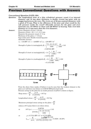
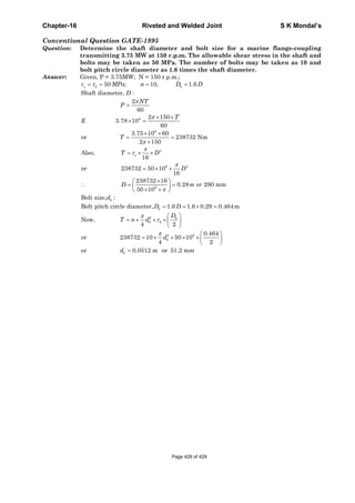

This document contains a table of contents for a book on strength of materials with 16 chapters covering topics like stress and strain, bending, torsion, columns, and failure theories. It also contains introductory material on stress, strain, Hooke's law, true stress and strain, volumetric strain, Young's modulus, shear modulus, and bulk modulus. Key definitions provided include normal stress, shear stress, tensile strain, compressive strain, engineering stress and strain, true stress and strain, Hooke's law, and the relationships between elastic constants.


