Downloaded 1,417 times
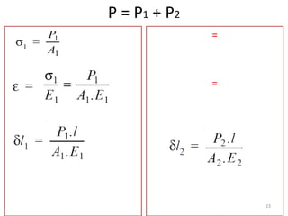
![Total Elongation: δ
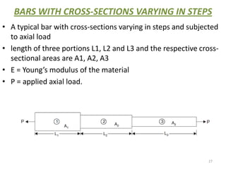
δ1 + δ2 + δ3 = [P L1 / A1 E] + [P L2 / A2 E] + [P L3 / A3 E]
30](https://image.slidesharecdn.com/simpalestressandsimplestrain-120606223038-phpapp01/85/Simpale-stress-and-simple-strain-30-320.jpg)
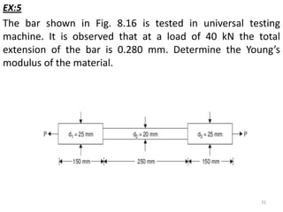

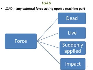
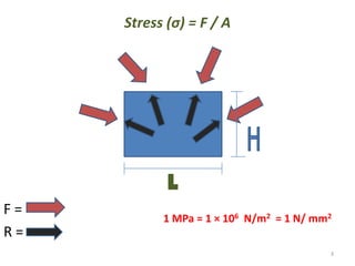
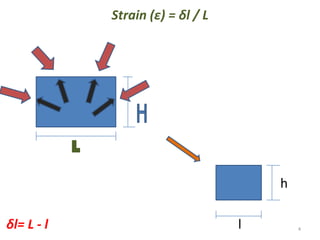
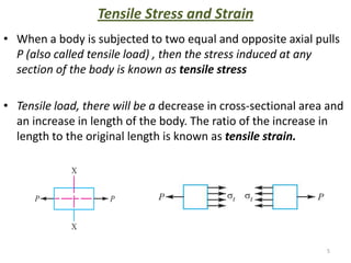
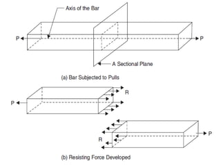
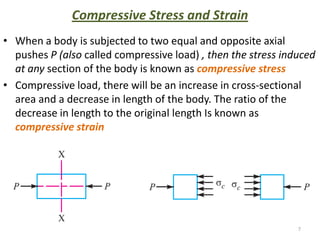
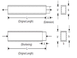
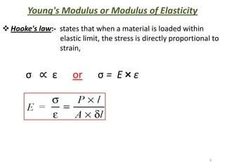
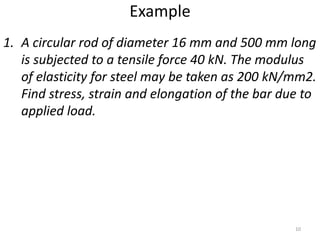
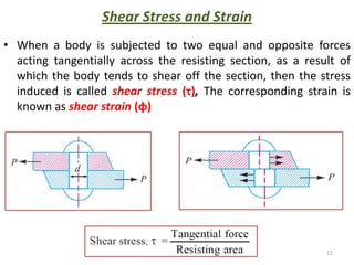
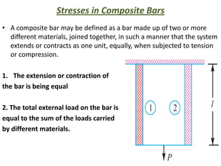
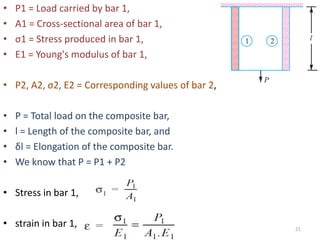
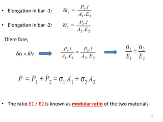
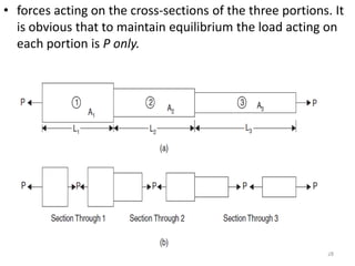
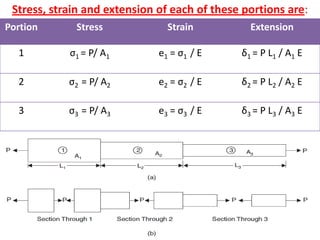
This document contains lecture notes on mechanics of solids from the Department of Mechanical Engineering at Indus Institute of Technology & Engineering. It defines key concepts such as load, stress, strain, tensile stress and strain, compressive stress and strain, Young's modulus, shear stress and strain, shear modulus, stress-strain diagrams, working stress, and factor of safety. It also discusses thermal stresses, linear and lateral strain, Poisson's ratio, volumetric strain, bulk modulus, composite bars, bars with varying cross-sections, and stress concentration. The document provides examples to illustrate how to calculate stresses, strains, moduli, and other mechanical properties for different loading conditions.