chaitra-1.pptx fake news detection using machine learning
Strength of materials
1. College of Engineering
Mech. Eng. Dept.
Subject: Strength of Materials
Second Class Lecturer: Sadiq Muhsin Almosawy
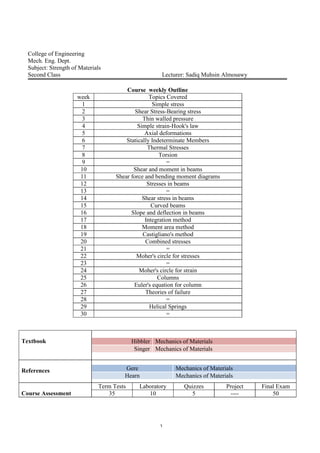
Course weekly Outline
week Topics Covered
1 Simple stress
2 Shear Stress-Bearing stress
3 Thin walled pressure
4 Simple strain-Hook's law
5 Axial deformations
6 Statically Indeterminate Members
7 Thermal Stresses
8 Torsion
9 =
10 Shear and moment in beams
11 Shear force and bending moment diagrams
12 Stresses in beams
13 =
14 Shear stress in beams
15 Curved beams
16 Slope and deflection in beams
17 Integration method
18 Moment area method
19 Castigliano's method
20 Combined stresses
21 =
22 Moher's circle for stresses
23 =
24 Moher's circle for strain
25 Columns
26 Euler's equation for column
27 Theories of failure
28 =
29 Helical Springs
30 =
Textbook Mechanics of MaterialsHibbler
Mechanics of MaterialsSinger
References Mechanics of MaterialsGere
Mechanics of MaterialsHearn
Course Assessment
Term Tests Laboratory Quizzes Project Final Exam
35 10 5 ---- 50
2. Strength of materials is a branch of applied mechanics that deals with the behavior of
solid bodies subjected to various types of loading. The solid bodies include axially-loaded
bars, shafts, beams, and columns. The objective of analysis will be the determination of the
stresses, strains, and deformations produced by the loads.
Simple Stress ( ):
If a cylindrical bar is subjected to a direct pull or push along its axis, then it is
said to be subjected to tension or compression.
P P P P
Tension Compression
In SI systems of units load is measured in Newton (N) or Kiloewton (KN) or
Meganewton (MN).
Normal stress ( ) : is the intensity of normal force per unit area
Stress =
Area
Load
A
P
stress may thus be compressive or tensile depending on the nature of the load and will be
measured in units of Newton per square meter (N/m2
). This unit, called Pascal
1 Pa=1 N/m2
1 KPa=1000 Pa=103
Pa
1 MPa=106
Pa
1 GPa=109
Pa
In the U.S. customary or foot-pound-second system of units, express stress in
pounds per square inch (Psi) or kilopound per square inch (Ksi)
Normal Strain ( ):
If a bar is subjected to a direct load, and hence a stress, the bar will change in
length. If the bar has an original length (L) and changes in length by an amount ( L), the
strain produced is defined as follows
3. Strain( )=
lengthoriginal
lengthinchange
L
L
P P
L L
Strain is thus a measure of the deformation of the material and is non-dimensional,
i.e. it has no units. Tensile stresses and strains are considered positive sense. Compressive
stresses and strains are considered negative in sense.
Shear Stress ( ) and Bearing Stress ( b ):
Shearing stress differs from both tensile and compressive stress in that it is
caused by forces acting along or parallel to the area resisting the forces, whereas tensile
and compressive stresses are caused by forces perpendicular to the areas on which they act.
For this reason, tensile and compressive stresses are called normal stresses, whereas a
shearing stress may be called a tangential stress.
A shearing stress is produced whenever the applied loads cause one section of a
body to tend to slide past its adjacent section.
Shear stress=
shearresistingArea
loadShear
Q
Q Q
Q
A
Q
Area resisting shear is the shaded area as shown above.
4. P P
P A
P
Single shear stress
P P
P/2
P
A
P/2
Double shear stress
Bearing stress is a normal stress that is produced by the compression of one
surface against another. The bearing area is defined as the projected area of the curved
bearing surface.
1
P P 2
3
b
b
b
A
F
Consider the bolted connection shown above, this connection consists of a flat bar
A, a clevis C, and a bolt B that passes through holes in the bar and clevis. Consider the
bearing stresses labeled 1, the projected area Ab on which they act is rectangle having a
height equal to the thickness of the clevis and a width equal to the diameter of the bolt, the
bearing force Fb represented by the stresses labeled 1 is equal to P/2. The same area and the
same force apply to the stresses labeled 3. For the bearing stresses labeled 2, the bearing
A
P
A
P 2/
A C
B
5. area Ab is a rectangle with height equal to the thickness of the flat bar and width equal to
the bolt diameter. The corresponding bearing force Fb is equal to the load P.
Shear Strain ( ):
Shear strain is a measure of the distortion of the element due to shear. Shear
strain is measured in radians and hence is non-dimensional, i.e. it has no units.
Elastic Materials-Hook's Law:
A material is said to be elastic if it returns to its original, when load is
removed. In elastic material, stress is proportional to strain. Hook's law therefore states
that:
Stress ( ) strain ( )
strain
stress
constant
Within the elastic limit, i.e. within the limits in which Hook's law applies, it has
been shown that:
E
This constant is given the symbol E and termed the modulus of elasticity or
Young's modulus.
Poisson's Ratio ( ):
Consider the rectangular bar shown below subjected to a tensile load. Under
the action of this load the bar will increase in length by an amount L giving a longitudinal
strain in the bar of:
L
L
L
The bar will also exhibit a reduction in dimensions laterally i.e. its breadth and
depth will both reduce.
6. The associated lateral strains will both be equal, will be of opposite sense to the
longitudinal strain, and will be given by:
b
b
d
d
lat
Poisson's ratio is the ratio of the lateral and longitudinal strains and always
constant
Poisson's ratio=
StrainalLongitudin
StrainLateral
LL
dd
/
/
Longitudinal Strain=
E
Lateral Strain=
E
Modulus of Rigidity ( G ):
For materials within the elastic range the shear strain is proportional to the shear
stress producing it.
StrainShear
StressShear
=Constant
=G
The constant G is termed the modulus of rigidity.
P P
b
d
2
b
2
d
7. Example 1:A 25 mm square cross-section bar of length 300 mm carries an axial
compressive load of 50 KN. Determine the stress set up in the bar and its change of length
when the load is applied. For the bar material E=200 GN/m2
.
Cross-section area of the bar(A)=25×10-3
×25×10-3
=625×10-6
m2
A
P
= 6
3
10625
1050
=80000000 N/m2
=80 MN/ m2
E
= 9
6
10200
1080
=0.0004
LL
L=0.0004×300×10-3
=0.12×10⁻³
m
L=0.12 mm
KN50
mm300
mm25
8. Example 2: Two circular bars, one of brass and the other of steel, are to be loaded by a
shear load of 30 KN. Determine the necessary diameter of the bars a) in single shear b) in
double shear, if the shear stress in the two materials must not exceed 50 MN/m2
and 100
MN/m2
respectively.
a) Single Shear
A
F F
A
For brass material
A= 6
3
1050
1030
=0.0006 m2
A= r2 A
r
0006.0
r
r=13.8197×10⁻³
m
the diameter of the bar (d)=27.639×10⁻³
m
For steel material
A= 6
3
10100
1030
=0.0003 m2
0003.0
r =9.772×10⁻³
m
the diameter of the bar (d)=19.544×10⁻³
m
b) Double Shear
A
F
2 2
F
A
For brass material
A= 6
3
10502
1030
=0.0003 m2
0003.0
r =9.772×10⁻³
m
the diameter of the bar (d)=19.544×10⁻³
m
For steel material
A= 6
3
101002
1030
=0.00015 m2
00015.0
r =6.909×10⁻³
m
the diameter of the bar (d)=13.819×10⁻³
m
9. Example 3: The 80 kg lamp is supported by two rods AB and BC as shown. If AB has a
diameter of 10 mm and BC has a diameter of 8 mm, determine the average normal stress in
each rod.
FBC=0.625FBA
FBC=1308-1.44337FBA
1308-1.44337FBA=0.625FBA
FBA=632.38 N
FBC=395.2375 N
BA
BA
BA
A
F
= 23
)105(
38.632
BA=8.051877×10⁶
Pa
BA=8.051877 MPa
BC
BC
BC
A
F
= 23
)104(
2375.395
BC=7.863149×10⁶
Pa
BC=7.863149 MPa
A
B
C
5
4
3
60
BCF
BAF
N8.78481.980
060cos
5
4
0
BABC
x
FF
F
08.78460sin
5
3
0
BABC
y
FF
F
10. Example 4: Shafts and pulleys are usually fastened together by means of a key, as shown.
Consider a pulley subjected to a turning moment T of 1 KN.m keyed by a 10 mm×10
mm×75 mm key to the shaft. The shaft is 50 mm in diameter. Determine the shear stress on
a horizontal plane through the key.
0oM
0025.0101 3
F
F=40000 N
F=40 KN
A
F
F
F
A is the shaded area
= 33
3
10751010
1040
=53.333×10⁶
N/m2
=53.333 MN/m2
Example 5: Consider a steel bolt 10 mm in diameter and subjected to an axial tensile load
of 10 KN as shown. Determine the average shearing stress in the bolt head, assuming
shearing on a cylindrical surface of the same diameter as the bolt.
A= dt
A= ×10×10-3
×8×10-3
=0.000251327 m2
A
F
=
000251327.0
1010 3
=39.7888×10⁶
N/m2
=39.7888 MN/m2
mm50
mm10
mm10
T
F
o
KN1
mm75
mm10
mm8
KN10
11. Example 6: The bar shown has a square cross section for which the depth and thickness are
40 mm. If an axial force of 800 N is applied along the centroidal axis of the bar's cross
sectional area, determine the average normal stress and average shear stress acting on the
material along a) section plane a-a and b) section plane b-b.
a) section plane a-a
A
P
= 33
10401040
800
=500 KN/m2
A
F
F=0
=0
b) section plane b-b
d=
60sin
40
=46.188 mm
A
F2
= 33
104010188.46
60sin800
=375 KN/m2
A
F1
= 33
104010188.46
60cos800
=216.50645 KN/m2
a
a b
b
60
N800
N800N800
N800 N80060
1F
2F
d
12. Example 7: Determine the total increase of length of a bar of constant cross section
hanging vertically and subject to its own weight as the only load. The bar is initially
straight.
: is the specific weight ( weight/unit volume )
A: is the cross-sectional area
AE
Aydy
d
L
d
0
=
L
AE
Aydy
0
=
L
ydy
AE
A
0
=
L
y
AE
A
0
2
2
1
= 2
2
L
AE
A
=
AE
LAL
2
.
W= AL
=
AE
LW
2
.
dy
yA
dy
y
L
13. Example 8: A member is made from a material that has a specific weight and modulus of
elasticity E. If its formed into a cone having the dimensions shown, determine how far its
end is displaced due to gravity when its suspended in the vertical position.
r
x
=
L
y
L
y
rx
v= yx2
3
w(y)= v= yx2
3
= y
L
yr
2
22
3
w(y)= 3
2
2
3
y
L
r
From equilibrium P(y)=w(y)
P(y)= 3
2
2
3
y
L
r
A(y)= x2
= 2
2
2
y
L
r
d =
Ey
L
r
dyy
L
r
EyA
dyyP
2
2
2
3
2
2
3
)(
)(
d = ydy
E3
LL
E
ydy
d
00
3
E
L
6
2
r
y
y
L
x
)(yw
)(yP
14. Example 9: A solid truncated conical bar of circular cross section tapers uniformly from a
diameter d at its small end to D at the large end. The length of the bar is L. Determine the
elongation due to an axial force P applied at each end as shown.
y
d
r
2
L
dD
x
y 22
L
xdD
y )
22
(
L
xdDd
r )
22
(
2
A(x)= r2
A(x)=
2
)
22
(
2 L
xdDd
d =
ExA
Pdx
)(
=
E
L
xdDd
Pdx
2
)
22
(
2
=
L
E
L
xdDd
Pdx
0
2
)
22
(
2
=
L
L
xdDd
dD
L
E
P
0
1
)
22
(
2
)
22
(
=
L
L
xdDddD
E
PL
0)
22
(
2
)
22
(
=
2
)
22
(
222
)
22
(
ddD
E
PL
dDddD
E
PL
=
)
44
()
44
(
22
dDd
E
PL
dDD
E
PL
= 22
114
dDddDDE
PL
=
dDE
PL4
d D
L
P P
r
y
dxx
P P
22
dD
15. Example 10: Determine the smallest dimensions of the circular shaft and circular end cop
if the load it is required to support is 150 KN. The allowable tensile stress, bearing stress,
and shear stress is ( t)allow=175 MPa, is ( b)allow=275 MPa, and allow=115 MPa.
( b)allow=
b
b
A
F
275×106
=
bA
3
10150
Ab=0.0005454 m2
Ab= 2
2
4
d
d2=
0005454.044 bA
d2=0.026353 m=26.353 mm
( t)allow=
A
P
175×106
=
A
3
10150
A=0.0008571 m2
A= ])1030([
4
232
1d =0.0008571
d1=0.04462 m=44.62 mm
allow=
A
F
115×106
=
A
3
10150
A=0.0013043 m2
1. A=t d
0.0013043= t× ×30×10-3
t=0.013839 m=13.839 mm
2. A=t d2
0.0013043= t× ×26.353×10⁻³
t=0.01575 m=15.75 mm
KNP 150
2d
1d
mm30
t
16. Statically Indeterminate Members:
If the values of all the external forces which act on a body can be
determined by the equations of static equilibrium alone, then the force system is statically
determinate.
In many cases the forces acting on a body cannot be determined by the equations of
static alone because there are more unknown forces than the equations of equilibrium. In
such case the force system is said to be statically indeterminate.
P
3R2R
1R
1R
2R 3R
1P
2P
P
3R2R
1R
4R
3R2R
1R
4R
P
1M
17. Example 11: A square bar 50 mm on a side is held rigidly between the walls and loaded
by an axial force of 150 KN as shown. Determine the reactions at the end of the bar and the
extension of the right portion. Take E=200 GPa.
R1+R2=150×103
1= 2
933
3
2
933
3
1
1020010501050
10150
1020010501050
10100 RR
0.1R1=0.15R2
R1=1.5R2 (2)
From equations (1) and (2)
1.5R2 + R2=150×103
R2 =60000 N
R1=90000 N
2= 933
3
933
3
2
1020010501050
1015060000
1020010501050
10150R
2=0.000018 m
2=0.018 mm
mm100 mm150
KN150KN150
2R1R
18. Example 12: A steel bar of cross section 500 mm2
is acted upon by the forces shown.
Determine the total elongation of the bar. For steel, E=200 GPa.
15 KN 10 KN
For portion AB
1=
AE
PL
= 96
33
1020010500
105001050
=0.00025 m=0.25 mm
For portion BC
2=
AE
PL
= 96
3
1020010500
11035
=0.00035 m=0.35 mm
For portion CD
3=
AE
PL
= 96
3
1020010500
5.11045
=0.000675 m=0.675 mm
T= 1+ 2+ 3
T=0.25+0.35+0.675=1.275 mm
KN50 KN45
mm500 m1 m5.1
A B C D
A B
KN50 KN50 KN50
KN15
KN35
CB
KN45KN45
C D
19. Example 13: Member AC shown is subjected to a vertical force of 3 KN. Determine the
position x of this force so that the average compressive stress at C is equal to the average
tensile stress in the tie rod AB. The rod has a cross-sectional area of 400 mm2
and the
contact area at C is 650 mm2
.
0yF
FAB+FC-3000=0
FAB+FC=3000
AB= C
C
C
AB
AB
A
F
A
F
66
1065010400
CAB FF
FAB=0.6153 FC
From equations (1) and (2)
FC=1857.24 N
FAB=1142.759 N
0AM
FC×200×10-3
-3000×x=0
3000
2.024.1857
x =0.123816 m=123.816 mm
mm200
KN3
x
A
B
C
mm200
KN3
x
A
C
ABF
CF
20. Example 14: The bar AB is considered to be absolutely rigid and is horizontal before the
load of 200 KN is applied. The connection at A is a pin, and AB is supported by the steel
rod EB and the copper rod CD. The length of CD is 1m, of EB is 2 m. The cross sectional
area of CD is 500 mm2
, the area of EB is 250 mm2
. Determine the stress in each of the
vertical rods and the elongation of the steel rod. Neglect the weight of AB. For copper
E=120 GPa, for steel E=200 GPa.
FCo×1+Fs×2-200×103
×1.5=0
FCo=300×103
-2 Fs
12
Cos
s=2 Co
CoCo
Co
ss
s
EA
LF
EA
LF
2
9696
1012010500
1
2
1020010250
2 Cos FF
FCo=1.2 Fs
From equations (1) and (2)
Fs=93750 N
FCo=112500 N
s
s
s
A
F
= 6
10250
93750
=375000000 Pa
s=375 MPa
Co
Co
Co
A
F
= 6
10500
112500
=225000000 Pa
Co=225 MPa
E
Ls
s = 9
6
10200
210375
=0.00375 m=3.75 mm
A B
C
D
E
m1 mm500 mm500
KN200
KN200
sFCoF
yA
xA
A B
C
D
E
Co
s
0AM
21. Thermal Stresses:
A change in temperature can cause a material to change its dimensions. If the
temperature increases, generally a material expands, whereas if the temperature decreases
the material will contract.
The deformation of a member having a length L can be calculated using the
formula:
T= × T×L
T=
AE
FL
= × T×L
T=E× × T
: Linear coefficient of thermal expansion. The units measure strain per degree of
temperature. They are (1/ºF) in the foot-pound-second system and (1/ºC) or (1/ºK) in SI
system.
T: Change in temperature of the member.
L: The original length of the member.
T: The change in length of the member.
Example 15: The A-36 steel bar shown is constrained to just fit between two fixed
supports when T1=60º F. If the temperature is raised to T2=120º F determine the average
normal thermal stress developed in the bar. For steel =6.6×10⁻⁶
1/ºF, E=29×103
Ksi.
0yF
FA-FB=F
T- F=0
T= × T×L
T=E× × T
=29×103
×6.6×10-6
×(120-60)
=11.484 Ksi
in5.0
in5.0
in20
AF
BF
A
B
T F
22. Example 16: A 2014-T6 aluminum tube having a cross sectional area of 600 mm2
is used
as a sleeve for an A-36 steel bolt having a cross sectional area of 400 mm2
. When the
temperature is T1=15º C, the nut hold the assembly in a snug position such that the axial
force in the bolt is negligible. If the temperature increases T2=80º C, determine the average
normal stress in the bolt and sleeve. For aluminum =23×10-6
1/ºC, E=73.1 GPa, for steel
=12×10-6
1/ºC, E=200 GPa.
0yF
Fsl-Fb=0
Fsl=Fb=F
FslTslFbTb )()()()(
[ × T×L+
AE
FL
]b=[ × T×L-
AE
FL
]sl
12×10-6
×0.15×(80-15)+ 96
1020010400
15.0F
= 23×10-6
×0.15×(80-15)- 96
101.7310600
15.0F
0.0052949×10⁻⁶
F=0.00010725
F=20255 N
b=
bA
F
= 6
10400
20255
b=50.637655 MPa
sl=
slA
F
= 6
10600
20255
sl=33.758436 MPa
mm150
Tsl )(
Fsl )(
Tb )(
Fb )(
PositionInitial
PositionFinal
bF slF
23. Example 17: The rigid bar shown is fixed to the top of the three posts made of A-36 steel
and 2014-T6 aluminum. The posts each have a length of 250 mm when no load is applied
to the bar, and the temperature is T1=20ºC. Determine the force supported by each posts if
the bar is subjected to a uniform distributed load of 150 KN/m and the temperature is
raised to T2=80ºC. For steel =12×10-6
1/ºC, E=200 GPa , for aluminum =23×10-6
1/ºC,
E=73.1 GPa.
Steel Aluminum Steel
0yF
2Fst+Fal
=( st)T-( st)F=( al)T-( al)F
[ × T×L-
AE
LFst
]st=[ × T×L-
AE
LFal
]al
12×10-6
×0.25×(80-20) - =23×10-6
×0.25×(80-20) -
1.20956×10⁻⁹
Fal-0.994718×10⁻⁹
Fst
From equations (1) and (2)
Fst=-16444.7 N
Fal=122888.8 N
mm300 mm300
mKN /150
mm250
mm40
mm60
mm40
stF stFalF
KN906.0150
PositionInitial
PositionFinal
Tst )(
Fst )(
Tal )(
Fal )(
923
10200)1040(
4
25.0stF
923
101.73)1060(
4
25.0alF
24. Example 18: The rigid bar AD is pinned at A and attached to the bars BC and ED as
shown. The entire system is initially stress-free and the weights of all bars are negligible.
The temperature of bar BC is lowered 25ºK and that of the bar ED is raised 25ºK.
Neglecting any possibility of lateral buckling, find the normal stresses in bars BC and ED.
For BC, which is brass, assume E=90 GPa, =20×10-6
1/ºK and for ED, which is steel,
take =12×10-6
1/ºK, E=200 GPa. The cross-sectional area of BC is 500 mm2
, of ED is
250 mm2
.
0AM
Pst×600×10-3
-Pbr×250×10-3
=0
Pst=0.41666 Pbr
600250
stbr
600250
stst
st
brbr
br
EA
LP
TL
EA
LP
TL
8.333×10⁻¹²
Pst+26.666×10⁻¹²
Pbr=475×10-9
2)
From equations (1) and (2)
Pbr=15760.5 N , Pst=6566.77 N
br= MPa521.31
10500
5.15760
6
Pst= MPa267.26
10250
77.6566
6
mm300
stP
brPyA
xA
A B
C
D
E
mm250 mm350
mm250
br Tst )(
Tbr )(
Fbr )(
Fst )( st
600
1020010250
10250
25102501012
250
109010500
10300
25103001020 96
3
36
96
3
36 stbr PP
25. Torsion:
Torque is a moment that tends to twist a member about its longitudinal axis.
When the torque is applied, the circles and longitudinal grid lines originally marked on the
shaft tend to distort into the pattern shown below.
Before deformation After deformation
Twisting causes the circles to remain circles and each longitudinal grid line
deforms into a helix that intersects the circles at equal angles. Also, the cross sections at
the ends of the shaft remain flat that is, they do not warp or bulge in or out and radial lines
on these ends remain straight during the deformation.
The Torsion Formula:
Consider a uniform circular shaft is subjected to a torque it can be shown
that every section of the shaft is subjected to a state of pure shear.
J
T
T
T
T
T
max
r
26. : The torsional shearing stress.
T: The resultant internal torque acting on the cross section.
: The distance from the centre (radial position).
J: The polar moment of inertia of the cross sectional area.
J
Tr
max
max: The maximum shear stress in the shaft, which occurs at the outer surface.
r: The outer radius of the shaft.
4
2
rJ
4
32
DJ
for a hollow shaft
J
Tr
J
Tro
max
)(
32
)(
2
4444
ioio DDrrJ
Angle of Twist ( ):
If a shaft of length L is subjected to a constant twisting moment along its
length, then the angle of twist through which one end of the shaft will twist relative to the
other is:
GJ
TL
G: The shear modulus of elasticity or
modulus of rigidity.
: Angle of twist, measured in rad
orir
r
T
T
r
L
A
27. If the shaft is subjected to several different torques or the cross sectional area or
shear modulus changes from one region to the next. The angle of twist of one end of the
shaft with respect to the other is then found from:
GJ
TL
In order to apply the above equation, we must develop a sign convention for the
internal torque and the angle of twist of one end of the shaft with respect to the other end.
To do this, we will use the right hand rule, whereby both the torque and angle of twist will
be positive, provided the thumb is directed outward from the shaft when the fingers curl to
give the tendency for rotation.
mN.10
mN.60
mN.150
ABL
BCL
CDL
A
B
C
D
mN.70
mN.80
A
B
ABL
B
BCL
C
mN.80
mN.80
mN.80
mN.150
mN.70
C
D
ABL
mN.60
mN.10
28. GJ
L
GJ
L
GJ
L CDBCAB
DA
107080
/
Power Transmission (P):
Shaft and tubes having circular cross sections are often used to transmit
power developed by a machine.
dt
d
TP ,
dt
d
: The shaft's angular velocity (rad/s).
TP
In SI units power is expressed in (watts) when torque is measured in (N.m) and
in (rad/s).
1 W=1 N.m/s
In the foot-pound-second or FPS system the units of power are (ft.lb/s); however
horsepower (hp) is often used in engineering practice where:
1 hp=550 ft.lb/s
For machinery the frequency of a shaft's rotation f is often reported. This is a
measured of the number of revolutions or cycles the shaft per second and is expressed in
hertz (1 Hz=1 cycle/s), 1 cycle=2 rad, then =2 f
P=2 fT
Example 19: If a twisting moment of 1 KN.m is impressed upon a 50 mm diameter shaft,
what is the maximum shearing stress developed? Also what is the angle of twist in a 1 m
length of the shaft? The material is steel, for which G=85 GPa.
J
Tr
max
6434
106135.0)1050(
3232
DJ m4
6
33
max
106135.0
1025101
max=40.74979 MPa
29. GJ
TL
69
3
106135.01085
1101
=0.01917 rad.
Example 20: The pipe shown has an inner diameter of 80 mm and an outer diameter of 100
mm. If its end is tightened against the support at A using a torque wrench at B, determine
the shear stress developed in the material at the inner and outer walls along the central
portion of the pipe when the 80 N forces are applied to the wrench.
T=80×200×10-3
+80×300×10-3
T=40 N.m
J
Tr
)(
32
44
io DDJ
4343
)1080()10100(
32
J
J=5.7962×10⁻⁶
m4
Inner walls ri=40 mm
J
Tri
= 6
3
107962.5
104040
=0.276042 MPa
Outer walls ro=50 mm
J
Tro
= 6
3
107962.5
105040
=0.345053 MPa
30. Example 21: The gear motor can developed 0.1 hp when it turns at 80 rev/min. If the
allowable shear stress for the shaft is allow=4 ksi, determine the smallest diameter of the
shaft that can be used.
J
Tr
allow
4
2
rJ
4
2
r
Tr
allow
3
2
r
T
allow
3
2
allow
T
r
P=T.
P
T
P=0.1×550=55 lb/s
=80×2 /60=8.377 rad/s
377.8
55
T =6.5655 lb.ft
T=6.5655×12=78.786 lb.in
3
3
104
786.782
r =0.2323 in
d=0.4646 in
31. Example 22: The assembly consists of a solid 15 mm diameter rod connected to the inside
of a tube using a rigid disk at B. Determine the absolute maximum shear stress in the rod
and in the tube. The tube has an outer diameter of 30 mm and a wall thickness of 3 mm.
The rod
T=50 N.m
r=7.5×10⁻³
m
4
2
rJ
43
)1075(
2
J
J=4.97009×10⁻⁹
m4
J
Tr
r
9
3
1097009.4
105.750
r =75.4512 MPa
The tube
T=80 N.m
r=15×10-3
m
)(
2
44
io rrJ
4343
)1012()1015(
2
J =46.9495×10⁻⁹
m4
J
Tro
t = 9
3
109495.46
101580
=25.559 MPa
mm12
mm15
32. Example 23: The tapered shaft shown below is made of a material having a shear modulus
G. Determine the angle of twist of its end B when subjected to the torque.
L
xdd
y
L
dd
x
y
22
1212
d=d1+2y=d1+
L
x
dd )( 12
4
121
4
])([
3232
)(
L
x
ddddxJ
0 4
121
0 4
121
0
])([
32
])([
32
)(
+
=
+
==
=
+
= 3
1
3
212
0
3
121
12
11
)(3
32
])([
1
)(3
32
= 3
1
3
2
3
2
3
1
12 .)(3
32
++
= 3
1
3
2
2
221
2
1
.3
32
1d
2dd
y
x
22
12 dd
x
33. Example 24: The gears attached to the fixed end steel shaft are subjected to the torques
shown. If the shear modulus of elasticity is G=80 GPa and the shaft has a diameter of 14
mm, determine the displacement of the tooth P on gear A.
Segment AC
150-TAC=0
TAC=150 N.m
Segment CD
150-280+TCD=0
TCD=130 N.m
Segment DE
-130-40+TDE=0
TDE=170 N.m
GJ
TL
= TL
GJ
1
= 5.01703.01304.0150
)107(
2
1080
1
439
=-0.21211 rad
34. Example 25: A steel shaft ABC connecting three gears consists of a solid bar of diameter d
between gears A and B and a hollow bar of outside diameter 1 .2 5 d and inside diameter d
between gears B and C. Both bars have length 0 .6 m. The gears transmit torques T1 2 4 0=
N.m, T2 5 4 0= N.m, and T3 3 0 0= N.m acting in the directions shown in the figure. The shear
modulus of elasticity for the shaft is 8 0 GPa. a) what is the minimum permissible diameter
d if the allowable shear stress in the shaft is 8 0 MPa?. b) what is the minimum permissible
diameter d if the angle of twist between any two gears is limited to 4 ?.
TAB 240= N.m
TBC 300= N.m
a)
1 . For solid bar AB
J= 4
32
d
4
32
2/2/
d
dT
J
dT ABAB
4
6
32
2/240
1080
d
d
6
3
1080
24016
d
0.02481d= m
24.81d= mm
2 . For hollow bar BC
J= ])25.1[(
32
][
32
4444
dddd io
])25.1[(
32
2/25.12/25.1
44
dd
dT
J
dT BCBC
])25.1[(
32
2/25.1300
1080
44
6
dd
d
4414.11080
25.130016
6
3
d
0 .0 2 5 5d= m
2 5 .5d= mm Answer
b)
1 . For solid bar AB
GJ
LTAB
35. 49
32
1080
6.0240
180
4
d
0.02263d= m
22.63d= mm
2 . For hollow bar BC
GJ
LTBC
])25.1[(
32
1080
6.0300
180
4
449
dd
0.02184d= m
21.84d= mm
0 .0 2 2 6 3d= m
2 2 .6 3d= mm Answer
Example 26: The shaft is subjected to a distributed torque along its length of t=10x2
N.m/m, where x is in meters. If the maximum stress in the shaft is to remain constant at 80
MPa, determine the required variation of the radius r of the shaft for 30 x m
tdxT
dxx2
10 3
3
10
x
J
Tr
max
3
3
6
4
3
6
3
20
1080
2
3
10
1080
r
x
r
rx
36. x
x
r 002982.0
10803
203
6
3
m
r=2.982 x mm
Example 26: The shaft has a radius 50 mm and is subjected to a torque per unit length of
100 N.m which is distributed uniformly over the shafts entire length 2 m. If it is fixed at its
far end A, determine the angle of twist of end B. The shear modulus is 73.1 GPa.
T(x)=100x
2
0 439
2
0 )1050(
2
101.73
100)( xdx
GJ
dxxT
2
0
2
439
2)1050(101.73
200 x
439
)1050(101.73
400
4
10786.2 rad
=0.01596o
m2
mmN /.100
38. Example 27: The solid steel shaft shown has a diameter of 20 mm. If it is subjected to the
two torques, determine the reactions at the fixed supports A and B.
-TB+800-500-TA=0
TB+TA ..(1)
0
3.05.1)500(2.0
GJ
T
GJ
T
GJ
T AAB
-0.2TB+1.5TA+750+0.3TA=0
1.8TA-0.2TB=-
TA=-345 N.m
TB=645 N.m
39. Example 28: The shaft shown below is made from steel tube, which is bonded to a brass
core. If a torque of T=250 lb.ft is applied at its end, plot the shear stress distribution along a
radial line of its cross sectional area. Take Gst11.4×103
ksi, Gbr=5.2×10³
ksi.
Tst+Tbr
st br
])5.0()1[(
2
102.5])5.0()1[(
2
104.11 446446
LTLT brst
Tst=32.88Tbr
From (1) and (2)
Tst=2911 lb.in=242.6 lb.ft
Tbr=88.5 lb.in=7.38 lb.ft
psibr 451
)5.0(
2
5.05.88
)(
4
max
psist 1977
])5.0()1[(
2
12911
)(
44
max
psist 988
])5.0()1[(
2
5.02911
)(
44
min
rad
G
3
66
100867.0
104.11
988
102.5
451
40. Torsion of Solid Noncircular Shafts:
Shape of cross section max
Square
Equilateral
triangle
Ellipse
Example 28: The 2014-T6 aluminum strut is fixed between the two walls at A and B. If it
has a 2 in by 2 in square cross section and it is subjected to the torsional loading shown,
determine the reactions at the fixed supports. Also what is the angle of twist at C. Take
G=3.9×10³ ksi.
TA-40-20+TB=0
TA+TB
A/B=0
0
109.32
122121.7
109.32
12212)20(1.7
109.32
122121.7
646464
BBA TTT
a 3
81.4
a
T
Ga
TL
4
1.7
a
a
a
3
20
a
T
Ga
TL
4
46
aa
b
b
2
2
ab
T
Gba
TLba
33
22
)(
Ga
TL
BA 4/
1.7
41. TA-2TB=-
From equations (1) and (2)
TB=26.666 lb.ft
TA=33.333 lb.ft
Ga
LTA
C 4
1.7
64
109.32
12212333.331.7
C
C=0.001092 rad
C=0.06258º
Thin walled tubes having closed cross sections:
Shear flow(q): is the product of the tube's thickness and the average shear stress. This value
is constant at all points along the tube's cross section. As a result, the largest average shear
stress on the cross section occurs where the tube's thickness is smallest.
The forces acting on the two faces are dFA= A(tAdx) , dFB= B(tBdx), these
forces are equal for equilibrium, so that:
AtA= BtB
q= avgt
AT
BT
ftlb.40
ftlb.20
C
D
42. Average shear stress( avg):
The average shear stress acting on the shaded
Area dA=tds
dF= avgdA= avgtds
dT=dF×h= avgtds×h
T= avgt hds
Area of triangle dAm=
2
1
hds
hds=2dAm
T=2 avgt mdA =2 avgtAm
avg=
mtA
T
2
avg: The average shear stress acting over the thickness of the tube.
T: The resultant internal torque at the cross section.
t: The thickness of the tube where avg is to be determined.
Am: The mean area enclosed within the boundary of the center line of the tube thickness.
q= avgt=
mA
T
2
Angle of Twist( ):
t
ds
GA
TL
m
2
4
43. Example 29: The tube is made of C86100 bronze and has a rectangular cross section as
shown below. If its subjected to the two torques, determine the average shear stress in the
tube at points A and B. Also, what is the angle of twist of end C? The tube is fixed at E.
Take G=38 GPa.
60-25-T=0
T=35 N.m
Am=(40×10-3
-5×10⁻³
)(60×10-3
-3×10⁻³
)
=0.001995 m2
A=
mtA
T
2
=
001995.01052
35
3
A=1.7543859 MPa
B=
mtA
T
2
=
001995.01032
35
3
B=2.9239766 MPa
t
ds
GA
TL
m
2
4
=
=0.0062912 rad
]
105
1057
2
103
1035
2[
108.3)001995.0(4
5.135
]
105
1057
2
103
1035
2[
108.3)001995.0(4
5.060
3
3
3
3
92
3
3
3
3
92
44. Example 30: A thin tube is made from three 5 mm thick A-36 steel plates such that it has a
cross section that is triangular as shown below. Determine the maximum torque T to which
it can be subjected, if the allowable shear stress is allow=90 MPa and the tube is restricted
to twist no more than =2×10⁻³
rad. Take G=75 GPa.
A=
2
1
(200×10-3
)× (200×10-3
sin60)=0.01732 m2
t=0.005 m
allow=
mtA
T
2
=
01732.01052 3
T
=90×106
T=15.588 KN.m
t
ds
GA
TL
m
2
4
2×10-3
= ]
105
10200
3[
1075)01732.0(4
3
3
3
92
T
T=500 N.m
45. Thin Walled Cylinder, Thin Walled Pressure Vessels:
Cylindrical or spherical vessels are commonly used in industry to serve as boilers
or tanks. When under pressure, the material of which they are made is subjected to a
loading from all directions. In general "thin wall" refers to a vessel having an inner radius
to wall thickness ratio of 10 or more (r/t 10)
1. Cylindrical Vessels:
Consider the cylindrical vessel having a wall thickness t and inner radius r as
shown below. A pressure p is developed within the vessel by a containing gas or fluid,
which is assumed to have negligible weight.
The stresses set up in the walls are:
a. Circumferential or hoop stress
2[ 1(tdy)]-p(2rdy)=0
t
pr
1
b. Longitudinal or axial stress
2(2 rt)-p( r2
)=0
t
pr
2
2
c. Circumferential or hoop strain
)(
1
211
E
d. Longitudinal strain
)(
1
122
E
46. e. Change in length
The change in length of the cylinder may be determined from the
longitudinal strain.
Change in length=longitudinal strain×original length
2L= )(
1
12
E
L
L= )21(
2tE
pr
L
f. Change in diameter
The change in diameter may be found from the circumferential change.
Change in diameter=diametral strain×original diameter
Diametral strain=circumferential strain
d= 1d= )(
1
21
E
d
d= )2(
2tE
pr
d
g. Change in internal volume
Volumetric strain=longitudinal strain+2diametral strain
v= 2+2 1= )(
1
12
E
+2 )(
1
21
E
diametral strain
v= )22(
1
2112
E
longitudinal strain
= )2
2
(
1
t
pr
t
pr
t
pr
t
pr
E
diametral strain
v= )45(
2tE
pr
change in internal volume=volumetric strain×original volume
v= vv
v= )45(
2tE
pr
v
47. 2. Spherical Vessels:
Because of the symmetry of the sphere the stresses set up owing to internal
pressure will be two mutually perpendicular hoop or circumferential stress of equal
value and a radial stress.
1(2 rt)-p( r2
)=0
t
pr
2
1
2=
t
pr
2
1
Change in internal volume
change in internal volume=volumetric strain×original volume
volumetric strain=3hoop strain
v= 1=3 )(
1
21
E
= )1(
3 1
E
= )1(
2
3
tE
pr
v= vv
v = )1(
2
3
tE
pr
v
48. Cylindrical Vessels with Hemispherical Ends:
r=d/2
a) For the cylindrical portion
ct
Pr
1 hoop stress
ct2
Pr
2 longitudinal stress
)(
1
211
E
= )
2
PrPr
(
1
cc ttE
1= )2(
2 Et
pr
c
hoop strain
b) For the spherical ends
st2
Pr
1 hoop stress
)(
1
211
E
= )1(1
E
1= )1(
2 Et
pr
s
hoop strain
Thus equating the two strains in order that there shall be no distortion of the
junction.
)1(
2 Et
pr
s
= )2(
2 Et
pr
c
2
1
c
s
t
t
49. Example 31: A thin cylinder 75 mm internal diameter, 250 mm long with walls 2.5 mm
thick is subjected to an internal pressure of 7 MN/m2
. Determine the change in internal
diameter and the change in length. If in addition to the internal pressure, the cylinder is
subjected to a torque of 200 N.m find the magnitude and nature of the stresses set up in the
cylinder.E=200 GN/m2
.
d= )2(
2tE
pr
d
d= 3
93
36
1075]3.02[
10200105.22
10
2
75
107
d=33.468×10⁻⁶
m=33.468 m
L= )21(
2tE
pr
L
L= 3
93
36
10250]3.021[
10200105.22
10
2
75
107
L=26.25×10⁻⁶
m=26.25 m
t
pr
1 = 3
36
105.2
10
2
75
107
1=105×106
N/m2
=105 MN/m2
t
pr
2
2 = 3
36
105.22
10
2
75
107
2=52.5×10⁶
N/m2
=52.5 MN/m2
J
Tr
=
][
2
44
io rr
Tr
=
])105.37()1040[(
2
1040200
4343
3
=8.743862 MN/m2
50. Example 32: A cylinder has an internal diameter of 230 mm, has walls 5 mm thick and is 1
m long. It is found to change in internal volume by 12×10-6
m3
when filled with a liquid at
a pressure p. If E=200 GN/m2
and , and assuming rigid end plates, determine a) the
values of hoop and longitudinal stresses b) the necessary change in pressure p to produce a
further increase in internal volume of 15%.
a) v= )45(
2tE
pr
v
12×10-6
= 1)10
2
230
(]25.045[
102001052
10
2
230
23
93
3
p
p=1.255763 MN/m2
t
pr
1 = 3
36
105
10
2
230
10255763.1
1=28.882549 MN/m2
t
pr
2
2 = 3
36
1052
10
2
230
10255763.1
2=14.4412745 MN/m2
b) v=1.15×12×10-6
=13.8×10⁻⁶
m3
v= )45(
2tE
pr
v
13.8×10-6
= 1)10
2
230
(]25.045[
102001052
10
2
230
23
93
3
p
p=1.444128 MN/m2
Necessary increase=1.444128-1.255763=0.188365 MN/m2
51. Vessels Subjected to Fluid Pressure:
If a fluid is used as the pressurization medium the fluid itself will change in
volume as pressure is increased and this must be taken into account when calculating the
amount of fluid which must be pumped into the cylinder in order to raise the pressure by a
specific amount.
The bulk modulus of a fluid is defined as:
bulk modulus k=
strainVolumetric
stressVolumetric
volumetric stress=pressure p
volumetric strain=
volumeoriginal
volumeinchange
=
v
v
k=
v
v
p
=
v
pv
change in volume of fluid under pressure=
k
pv
extra fluid required to raise cylinder pressure by p
= )45(
2tE
pr
v+
k
pv
extra fluid required to raise sphere pressure by p
= )1(
2
3
tE
pr
v+
k
pv
52. Example 33: a) A sphere 1m internal diameter and 6 mm wall thickness is to be pressure
tested for safety purposes with water as the pressure medium. Assuming that the sphere is
initially filled with water at atmospheric pressure, what extra volume of water is required
to be pumped in to produce a pressure of 3 MN/m2
gauge? For water k=2.1 GN/m2
b) The sphere is now placed in service and filled with gas until there is a volume change of
72×10-6
m3
. Determine the pressure exerted by the gas on the walls of the sphere. c) To
what value can the gas pressure be increased before failure occurs according to the
maximum principal stress theory of elastic failure? E=200 GPa, and the yield stress
is simple tension=280 MPa.
a) extra volume of water= )1(
2
3
tE
pr
v+
k
pv
= 9
36
3
93
6
101.2
)5.0(
3
4
103
)5.0(
3
4
)3.01(
102001062
5.01033
=0.001435221 m3
b) v= )1(
2
3
tE
pr
v
72×10-6
= 3
93
)5.0(
3
4
)3.01(
102001062
5.03p
p=0.31430827 MN/m2
t
pr
2
1 1=yield stress for maximum principal stress theory
280×106
= 3
1062
5.0p
p=6.72 MN/m2
53. Shear and Moment Diagram:
Beams are long straight members that carry loads perpendicular to their
longitudinal axis. They are classified according to the way they are supported, e.g. simply
supported, cantilevered, or overhanging.
Simply supported beam overhanging beam
Cantilevered beam
Types of Loading:
Loads commonly applied to a beam may consist of concentrated forces(applied at
a point), uniformly distributed loads, in which case the magnitude is expressed as a certain
number of newtons per meter of length of the beam, or uniformly varying loads. A beam
may also be loaded by an applied couple.
(point load)
(concentrated force)
P P
P
N100
54. V V
MM
V V
M
Uniformly distributed load Uniformly varying load
Shearing force and bending moment diagrams show the variation of these
quantities along the length of a beam for any fixed loading condition. At every section in a
beam carrying transverse loads there will be resultant forces on either side of the section
which, for equilibrium, must be equal and opposite.
Shearing force at the section is defined as the algebraic sum of the forces taken on
one side of the section. The bending moment is defined as the algebraic sum of the
moments of the forces about the section, taken on either side of the section.
Sign Convention:
Forces upwards to the left of a section or downwards to the right of a section are
positive. Clockwise moments to the left and counter clockwise to the right are positive.
- -
Procedure of Analysis:
The shear and moment diagrams for a beam can be constructed using the
following procedure:-
1. Determine all the reactive forces and couple moments acting on the beam, and
resolve all the forces into components acting perpendicular and parallel to the beam's
axis.
2. Specify separate coordinates x having an origin at the beam's left end extending to
regions of the beam between concentrated forces and/or couple moments, or where
there is no discontinuity of distributed loading.
3. Section the beam perpendicular to its axis at each distance x, and draw the free body
diagram of one of the segments. Be sure V and M are shown acting in their positive
sense, in accordance with the sign convention given as above.
4. The shear is obtained by summing forces perpendicular to the beam's axis.
5. The moment is obtained by summing moment about the sectioned end of the
segment.
mN /10 mN /10
m4 m5
mN /5
M
55. 6. Plot the shear diagram(V versus x) and the moment diagram(M versus x). If
numerical values of the functions describing V and M are positive, the values are
plotted above the x-axis, whereas negative values are plotted below the axis.
Example 33: Draw the shear and moment diagrams for the beam shown below.
0xF
Ax=0
0CM
P×L/2-Ay×L=0
Ay=P/2
0yF
Cy+Ay-P=0
Cy=P/2
Segment AB
0yF
2
P
-V=0
V=
2
P
0M
M-
2
P
×x=0
M=
2
P
x
Segment BC
0yF
A
P
B C
2/L 2/L
xA
P
B
yCyA
2
P
x
V M
2
P
x
V
M
P
57. Example 34: Draw the shear and moment diagrams for the beam shown below.
0xF
Fx=0
0FM
-Ay×12+10×10-20×8+20×6
+30×2=0
Ay=10 KN
0yF
10-10+20-20-30+Fy=0
Fy=30 KN
Segment AB 20 x
0yF
10-V=0
V=10 KN
0M
M-10×x=0
M=10x
Segment BC 42 x
0yF
10-10-V=0
V=0
0M
M-10x+10(x-2)=0
M=20 KN.m
Segment CD 64 x
0yF
A
KN10
C
m4 m8
KN20
KN20 KN30
B D E F
m4 m2m2
A
KN10
C
m4 m8
KN20
KN20 KN30
B D E F
m4 m2m2
yA
yF
xF
KN10
x
V M
KN10
58. 10-10+20-V=0
V=20 KN
0M
M-10x+10(x-2)-20(x-4)=0
M=20(x-3)
Segment DE 106 x
0yF
10-10+20-20-V=0
V=0
0M
M-10x+10(x-2)-20(x-4)+20(x-6)=0
M=60 KN.m
Segment EF 1210 x
0yF
10-10+20-20-30-V=0
V=-30 KN
0M
M-10x+10(x-2)-20(x-4)+20(x-6)
+30(x-10)=0
M=30(12-x)
KN10
x
V M
KN10
KN20
KN10
x
V M
KN10
KN20
KN20
KN10
x
V M
KN10
KN20
KN20 KN30
60. Example 35: Draw the shear and moment diagrams for the beam shown below.
0xF
Ax=0
0BM
wL
2
L
-AyL=0
Ay=
2
wL
0yF
2
wL
+By-wL=0
By=
2
wL
0yF
2
wL
-wx-V=0
V=-w(x-
2
L
)
0M
M-
2
wL
x+wx(
2
x
)=0
M=
2
w
(xL-x2
)
A B
L
w
A B
L
wL
yA yB
xA
2
wL
x
V M
wx
2/x
w
Maximum moment occur when 0
dx
dM
2
02
0)2(
2
L
x
xL
xL
w
dx
dM
Location of maximum moment
62. Example 36: Draw the shear and moment diagrams for the beam shown below.
0xF
Ax=0
0yF
Ay=
2
Lwo
0AM
MA-
2
Lwo
L
3
2
=0
MA=
3
2
Lwo
0yF
2
Lwo
-
L
xwo
2
2
-V=0
V=
2
ow
(L-
L
x2
)
Vmax=
2
Lwo
0M
M+
3
2
Lwo
-
2
Lwo
x+
L
xwo
2
2
x
3
1
=0
A B
L
ow
L
3
2 L
3
1
2
Lwo
xA
yA
AM
L
xwo
2
2
3
2
Lwo
2
Lwo
x
L
x
ww o
3/x
V M
Maximum shear force occur at 0
dx
dV
0
L
xw
dx
dV o
x=0
64. Example 37: The horizontal beam AD is loaded by a uniform distributed load of 5 KN per
meter of length and is also subjected to the concentrated force of 10 KN applied as shown
below. Determine the shearing force and bending moment diagrams.
0xF
Ax=0
0AM
Cy×3-30×2=0
Cy=20 KN
0yF
Ay+20-30=0
Ay=10 KN
Segment AB 20 x
0yF
10-5x-V=0
V=10-5x
0M
M-10x+5x
2
x
=0
M=5x(2-
2
x
)
Segment BC 32 x
0yF
10-5x-10-V=0
V=-5x
0M
M-10x+5x
2
x
+10(x-2)=0
M=20-
2
5
x2
Segment CD 43 x
m2 m1 m1
mKN /5
KN10
A
B
C
D
KN10
xA
yA yC
KN20
KN10
x
V M
x5
2/x
mKN /5
x
V M
x5
mKN /5
KN10
2/x
KN10
66. Example 38: A beam ABC is simply supported at A and B and has an overhang BC. The
beam is loaded by two forces P and a clockwise couple of moment Pa that act through the
arrangement shown. Draw the shear force and bending moment diagrams for beam ABC.
0DM
-Pa+RC(2a)-Pa=0
RC=P
0yF
RD+P-P-P=0
RD=P
0AM
RB(2a)-Pa-P(3a)=0
RB=2P
0yF
RA+2P-P-P=0
RA=0
Segment AD ax0
0yF
V=0
0M
M=0
Segment DB axa 2
a a a a
P P
Pa
A
B
C
D
P P
Pa
DR CRP
AR BR
P
V M
x
V
x
P
68. Graphical Method for Constructing Shear and Moment Diagram:
)(xw
dx
dV
Slope of shear diagram at each point=-distributed load intensity at each point.
V
dx
dM
Slope of moment diagram at each point=shear at each point.
When the force acts downward on the beam, V is negative so the shear will jump
downward. Likewise, if the force acts upward, the jump will be upward.
If moment Mo is applied clockwise on the beam, M is positive so the moment
diagram will jump upward. Likewise, when Mo acts counterclockwise, the jump will
be downward.
)(xw
69. Example 39: Draw the shear and moment diagrams for the beam shown below.
0xF
Ax=0
0yF
Ay-P=0
Ay=P
0AM
M-PL=0
M=PL
At x=0 V=P
At x=L V=P
At x=0 M=-PL
At x=L M=0
P
L
A
P
xA
yA
M
P
PL
70. Example 40: Draw the shear and moment diagrams for the beam shown below.
0AM
By×5.5-10-60×2=0
By=23.63 KN
0yF
23.63+Ay-60=0
Ay=36.37 Kn
0xF
Ax=0
mKN /15
mKN.10
A B
m4 m5.0 m1
mKN /15
mKN.10
xA
yB
m4 m5.0 m1
yA
mKN /15
mKN.10
KN63.23
m4 m5.0 m1
KN37.36
KN37.36
KN63.23KN63.23
63.23
4
37.36
xx
23.63x=36.37×4-36.37x
x=2.4246 m
Maximum bending moment occur
when V=0, at x=2.4246 m
x
x4
mKN.092.44
mKN.48.25
mKN.665.23
mKN.665.13
71. Example 41: Draw the shear and moment diagrams for the beam shown below.
0CM
80-RB×6+30×7.5+144×4=0
RB=146.83 KN
0yF
RC+146.83-30-144=0
RC=27.17 KN
mKN /10
mKN /48
A B
C
mKN.80
m3 m6
KN30
mKN.80
m2m5.1
BR CR
KN144
mKN /10
mKN /48
A B
C
mKN.80
m3 m6
KN83.146 KN17.27
KN30
KN83.116
KN17.27
mKN.45
mKN.125
mKN.187.47
For segment 63 x
V=116.83+4(x-3)2
-48(x-3)
Maximum bending moment occur when
V=0
0=116.83+4(x-3)2
-48(x-3)
x2
-18x+74.2075=0
x=6.39375 m from left end
m39375.3
72. Example 42: Draw the shear and moment diagrams for the beam shown below.
0xF
Ax=0
0AM
By×6-9×7=0
By=10.5 KN
0yF
Ay+10.5-9=0
Ay=-1.5 KN
mKN/3
A B
C
m3 m3 m3
mKN/3
yA yB
xA
m2
mKN/3
KN9
KN5.10
KN5.1
KN5.1
KN75.3
KN75.6
mKN.5.4
mKN.25.11
73. Stresses in Beams:
Pure bending refers to flexure of a beam under a constant bending moment.
Therefore, pure bending occurs only in regions of a beam where the shear force is zero.
Nonuniform bending refers to flexure in the presence of shear forces, which means that the
bending moment changes as we move along the axis of the beam.
S.F. Diagram
B.M. Diagram
Nonuniform bending Pure bending
Assumptions:
1. The beam is initially straight and unstressed.
2. The material of the beam is perfectly homogeneous.
3. The elastic limit is nowhere exceeded.
4. Young's modulus for the material is the same in tension and compression.
5. Plane cross-sections remain plane before and after bending.
6. Every cross-section of the beam is symmetrical about the plane of bending i.e. about
an axis perpendicular to the N.A.
7. There is no resultant force perpendicular to any cross-section.
If we now considered a beam initially unstressed and subjected to a constant bending
moment along its length, i.e. pure bending as would be obtained by applying equal couples
at each end, it will bend to a radius as shown below.
P P
a a
P
P
Pa
74. As a result of this bending the top fibers of the beam will be subjected to
compression and the bottom to tension. Its reasonable to suppose, that somewhere between
the two there are points at which the stress is zero, these points is termed the neutral axis.
The neutral axis will always pass through the centre of area or centroid.
The length L1 of the line ef after bending takes place is:
L1=( -y)d
d =
dx
L1=(1-
y
)dx
The original length of line ef is dx
x)=
lengthoriginal
lengthoriginalL1
=
dx
dxdx
y
)1(
= -
y
x=-ky
where k is the curvature.
The longitudinal normal strain will vary linearly with y from the neutral axis. A
contraction (- x) will occur in fibers located above the neutral axis (+y), whereas
x) will occur in fibers located below the neutral axis (-y).
N.A
x=-(
1c
y
) max
By using Hook's law x x
x=-Eky=-
E
y
max
x
75. N.A
x=-(
1c
y
) max
Normal stress will vary linearly with y from the neutral axis. Stress will vary from
zero at the neutral axis to a maximum value max a distance c1 farthest from neutral axis.
N.A.
dF= xdA
M=
A
ydF = ydA
A
x )(
=
A
ydA
c
y
)( max
1
M=
A
dAy
c
2
1
max
A
dAy2
=I moment of inertia
I
Mc1
max
max: The maximum normal stress in the member, which occurs at a point on the cross
sectional area farthest away from the neutral axis.
M: The resultant internal moment.
I: The moment of inertia of the cross sectional area computed about the neutral axis.
c1: The perpendicular distance from the neutral axis to a point farthest away from the
neutral axis, where max acts.
max
76. 1=-
I
Mc1
, 2=
I
Mc2
1=-
1S
M
, 2=
2S
M
S1=
1c
I
, S2=
2c
I
The quantities S1 and S2 are known as the section moduli of the cross sectional
area.
Example 43: A simple beam AB of span length L=22 ft supports a uniform load of
intensity q=1.5 k/ft and a concentrated load P=12 k. The uniform load includes an
allowance for the weight of the beam. The concentrated load acts at a point 9 ft from the
left hand end of the beam. The beam is constructed of glued laminated wood and has a
cross section of width b=8.75 in and height h=27 in. Determine the maximum tensile and
compressive stresses in the beam due to bending.
ft22
ft9
kP 12
ftkq /5.1
A B
78. Example 44: The simply supported beam has the cross sectional area shown below.
Determine the absolute maximum bending stress in the beam and draw the stress
distribution over the cross section at this location.
in75.8
in271c
2c
c1=c2=13.5 in
1=
I
Mc1
I=
12
3
bh
= 4
3
1875.14352
12
)27(75.8
in
1=
1875.14352
5.1310828.1818 3
=-1710.8317 psi
1=
1875.14352
5.1310828.1818 3
=1710.8317 psi
A B
mKN /5
m6
mm250
mm300
mm20
mm20
mm20
KN30
yA
yB
80. B=
I
MyB
= 6
33
10333.301
10150105.22
=11.200233 MPa.
Example 45: The beam shown below has a cross section of channel shape with width
b=300 mm and height h=80 mm, the web thickness is t=12 mm. Determine the maximum
tensile and compressive stresses in the beam due to uniform load.
0AM
By×3-14.4×2.25=0
By=10.8 KN
0yF
Ay+10.8-14.4=0
Ay=3.6 KN
0xF
Ax=0
B
m3 m5.1
mKN /2.3
A
B
mm300
mm80
mm12
xA
yA
KN4.14
yB
mKN /2.3
81. M1=2.025 KN.m
M2=3.6 KN.m
A
Ay
yc
6
9
105232
10321888
cy =61.52×10⁻³
m
yc=61.52 mm
I1= 2
3
12
Ad
bh
No. of Area A(m2
) y (m) Ay (m3
)
1 960×10-6
40×10-3
38400×10-9
2 3312×10-6
74×10-3
245088×10-9
3 960×10-6
40×10-3
38400×10-9
A=5232×10-6
Ay =321888×10-9
KN6.3 KN8.10
KN6.3
KN6
KN8.4
mKN.025.2
mKN.6.3
mm300
mm80
mm12
1
2
3
mm80
mm12
mm300
mmc 52.611
mmc 48.182
82. I1=
12
)1080(1012 333
+960×10-6
×(21.52×10-3
)2
=0.95658×10⁻⁶
m4
I3= I1=0.95658×10⁻⁶
m4
I2= 2
3
12
Ad
bh
I2=
12
)1012(10276 333
+3312×10-6
×(12.48×10-3
)2
=0.55558×10⁻⁶
m4
I= I1+ I2+ I3=2.46874×10⁻⁶
m4
462179.50
1046874.2
1052.6110025.2
)( 6
33
21
1
I
cM
t MPa
94815.26
1046874.2
1048.18106.3
)( 6
33
12
2
I
cM
t MPa
( t)max=50.462179 MPa
158339.15
1046874.2
1048.1810025.2
)( 6
33
11
1
I
cM
c MPa
71054.89
1046874.2
1052.61106.3
)( 6
33
22
2
I
cM
c MPa
( c)max=-89.71054 MPa
Composite Beams:
Composite beams are made from different materials in order to efficiently carry a
load.
Normal stress in material 1 is determined from =E1
Normal stress in material 2 is determined from =E2
dA=dydz
The force dF acting on the area dA of the beam is
dF= dA=( E1
If the material 1 is being transformed into material 2
b2=nb
83. AdFd =( E2 )ndydz
dF= Fd
( E1 )dydz=( E2 )ndydz
n=
2
1
E
E
n: transformation factor (modular ratio).
If the material 2 is being transformed into material 1
b1=n b where n =
1
2
E
E
For the transformed material
=n
84. Example 46: A composite beam is made of wood and reinforced with a steel strap located
on its bottom side. It has the cross sectional area shown below. If the beam is subjected to a
bending moment of M=2 KN.m determine the normal stress at point B and C. Take Ew=12
GPa and Est=200 GPa.
st
w
E
E
n
06.0
200
12
n
wst bnb
mmbst 915006.0
mm150
mm150
mm20
B
C
mm150
C
mm20
mm150
mm9
B
1
2
mm150
mm150
mm9
mm20
86. Shear Stresses in Beams
A
ydA
It
V
AyydA
A
=Q
It
VQ
:- the shear stress in the member at the point located a distance y from the neutral axis.
V:-the internal resultant shear force.
I:-the moment of inertia of the entire cross sectional area computed about the neutral axis.
t:-the width of the members cross sectional area, measured at the point where is to be
determined.
Q Ay , where A is the top (or bottom) portion of the members cross sectional area,
defined from the section where t is measured, and y is the distance to the centroid of A ,
measured from the neutral axis.
87. Example 47: A metal beam with span L=3 ft is simply supported at points A and B. The
uniform load on the beam is q=160 lb/in. The cross section of the beam is rectangular with
width b=1 in and height h=4 in. Determine the normal stress and shear stress at point C,
which is located 1 in below the top of the beam and 8 in from the right hand support.
0AM
By×3×12-5760×1.5×12=0
By=2880 lb
0yF
Ay+2880-5760=0
Ay=2880 lb
A B
ft3
inlbq /160
C
lb5760
yA yB
lb2880
inlbq /160
lb2880
in18
inkM .92.25max
lb2880
lb2880
in18
C
in8
V
18
2880
10
V
V=1600 lb
88. At point C x=28 in from left end
from shear force diagram
N.A
4
33
3333.5
12
)4(1
12
in
bh
I
A =1×1=1 in2
y =1.5 in
Q Ay =1.5×1=1.5 in3
ksi
I
My
C 36.3
3333.5
117920
It
VQ
psi450
13333.5
5.11600
101600
2
1
182880
2
1
M
M=17.92 k.in
A
y
in1
in4
in1
89. Example 48: Consider the cantilever beam subjected to the concentrated load shown
below. The cross section of the beam is of T-shape. Determine the maximum shearing
stress in the beam and also determine the shearing stress 25 mm from the top surface of the
beam of a section adjacent to the supporting wall.
0AM
M-50×2=0
M=100 KN.m
0yF
Ay-50=0
Ay=50 KN
S.F. Diagram
B.M. Diagram
From shear and bending moment diagrams
V=50 KN
M=100 KN.m
A B
KN50
m2
mm200
mm50
mm50
mm125
M
B
KN50
m2
yA
mKN.100
B
KN50
m2
KN50
KN50
mKN.100
mm200
mm50
mm50
mm125
1
2
91. Q Ay
A =50×10-3
×25×10-3
=0.00125 m2
y =103.85×10⁻³
m
Q=0.000129812 m3
It
VQ
MPa272441.3
1050106684.39
000129812.01050
36
3
mm200
mm50
mm50
mm125
1
AN.
mmc 65.582
mmc 35.1161
A
y
mm25
92. Curved Beams
Due to the curvature of the beam, the normal strain in the beam does not vary linearly with depth as in the
case of a straight beam As result, the neutral axis does not pass through the centroid of the cross section
7C
If we isolate a differential segment of the beam let a strip material located at r distance has an original length
R r
Strain is a nonlinear function of r, in fact it varies in a hyperbolic fashion Hooke's law applies,
0RF
AA
dA
r
rR
EkdA 0)(0
AA
dA
r
dA
R 0
)(,
)(
r
rR
k
d
k
rd
rR
)(
r
rR
Ek
93. )( yRAe
My
R The location of the neutral axis, specified from the center of curvature 0' of the member
A The cross sectional area of the member
r The arbitrary position of the area element dAon the cross section, specified from the center of
curvature 0' of the member
y R r , e r R
The normal stress in the member
M The internal moment, determined from the method of sections equations of equilibrium and computed about
the centroidal axis
A The cross sectional area of the member
R The distance measured from the center of curvature to the neutral axis
r The distance measured from the center of curvature to the centroid of the cross sectional area
r The distance measured from the center of curvature to the point where the stress is to be determined
A
r
dA
A
R
94. )(
)(
RrAr
RrM
o
o
o
)(
)(
RrAr
rRM
i
i
i
Normal stress at the bar's top
Normal stress at the bar's bottom
Example:-The curved bar has a cross sectional area shown below If it is subjected to bending moments of 4
normal stress developed in the bar
Area A(mm2
) y-
(mm) y-
A(mm3
)
rectangle 2500 225 562500
triangle 750 260 195000
3250 757500
mm
A
Ay
r 076.233
3250
757500
A
r
dA
A
R
mmA 3250
b
r
r
rr
br
r
r
b
R
dA
1
2
12
2
1
2
ln
)(
ln
= mm04389.1450
250
280
ln
)250280(
28050
200
250
ln50
mmR 417.231
04389.14
3250
96. Area(mm2
) A(mm2
) y-
(mm) y-
A(mm3
)
rectangle 720 45 32400
Triangle -120 51.666 -6200
Triangle -120 51.666 -6200
480 20000
mm
A
Ay
r 666.41
480
20000
M=W×d=5000×(100×10-3
+41.666×10⁻³
)=708.33 N.m
MPa
A
W
RrAr
rRM
i
i
i
747.296
10480
5000
)108175.3810666.41(102510480
)1025108175.38(33.708
)(
)(
63336
33
MPa
A
W
RrAr
RrM
o
o
o
26.198
10480
5000
)108175.3810666.41(106510480
)108175.381065(33.708
)(
)(
63336
33
97. Slop and Deflection in Beams
The elastic curve :-the deflection diagram of the longitudinal axis that passes
through the centroid of each cross sectional area of the beam.
98. x-axis extends positive to the right.
v-axis extends positive upward from the x-axis.
y
1
E
I
My
EI
M1
When M is positive, extends above the beam, i.e. in the positive v direction.
When M is negative, extends below the beam, or in the negative v direction.
Integration Method
The elastic curve for a beam can be expressed mathematically as v=f(x)
2/32
22
])/(1[
/1
dxdv
dxvd
2/32
22
])/(1[
/
dxdv
dxvd
EI
M
The slop of the elastic curve which is determined from dv/dx will be very small, and
its square will be negligible compared with unity.
2
2
1
dx
vd
2
2
dx
vd
EI
M
99. dx
dM
V
)()( 2
2
dx
vd
EI
dx
d
xV
dx
dV
w
)()( 2
2
2
2
dx
vd
EI
dx
d
xw
EI always positive quantity
)( 2
2
dx
vd
EIM
)( 3
3
dx
vd
EIV
)( 4
4
dx
vd
EIw
Sign convention and coordinates
Positive deflection v is upward, the positive slope will be measured
counterclockwise from the x-axis when x is positive to the right.
If positive x is directed to the left, then will be positive clockwise.
dx
dv
100. Boundary conditions
1CMdx
dx
dv
EI
21][ CxCdxMdxEIv
Example: The cantilevered beam shown is subjected to a vertical load P at its end.
Determine the equation of elastic curve. EI is constant.
0M
M+Px=0
M=-Px
)( 2
2
dx
vd
EIM =-Px
1
2
2
1
CPx
dx
dv
EI
21
3
6
1
CxCPxEIv
Boundary conditions
101. at x=L
dx
dv
=0 and v=0
1
2
2
1
0 CPL 2
1
2
1
PLC
2
33
2
1
6
1
0 CPLPL 33
2
2
1
6
1
PLPLC =
3
3
PL
22
2
1
2
1
PLPxEI )(
2
22
xL
EI
P
326
1 32
3 PL
x
PL
PxEIv
)23(
6
323
LxLx
EI
P
v
Example: The simply supported beam shown supports the triangular distributed loading.
Determine the maximum deflection. EI is constant.
2
L
0M
0
34
3
L
xw
x
Lw
M )
34
(
3
L
x
x
L
wM
)( 2
2
dx
vd
EIM = )
34
(
3
L
x
x
L
w
1
4
2
128
C
L
xw
x
Lw
dx
dv
EI
21
5
3
6024
CxC
L
xw
x
Lw
EIv
102. Boundary conditions
at x=
2
L
dx
dv
=0
1
4
2
128
0 C
L
xw
x
Lw
192
5 3
1
Lw
C
at x=0 v=0
0=0-0+0+C2 C2=0
)
192
5
6024
(
35
3
x
L
L
x
x
L
EI
w
v
Vmax at x=
2
L
)
384
5
1920192
(
444
max
LLL
EI
w
v =
EI
Lw 4
120
Discontinuity Method
103. axforax
axfor
ax n
n
)(
0
C
n
ax
dxax
n
n
1
1
Example:- Find the moment expression using continuity equations.
M=2.75<x-0>1
+1.5<x-3>0
-
2
3
<x-3>2
-
6
1
<x-3>3
=2.75x+1.5<x-3>0
-
2
3
<x-3>2
-
6
1
<x-3>3
Example:- Determine the equation of the elastic curve for the beam shown below. EI is
constant.
0yF
Ay-40-12=0 Ay=52 kN
0AM
MA-40×2.5-50-12×9=0 MA=258 kN.m
105. Theorem 1 The angle between the tangents at any two points on the elastic curve equals
the area under the M/EI diagram between these two points.
If the area under M/EI diagram is positive, the angle is measured counterclockwise
from the tangent A to tangent B.
If the area under M/EI diagram is negative, the angle AB/ is measured clockwise from
tangent A to tangent B. AB/ will measured in radians.
B
A
BA dx
EI
M
xt /
BAt / : the vertical deviation of the tangent at A with respect to the tangent at B.
dAxxdA
B
A
dx
EI
M
represents the area under the M/EI diagram, we can also write:-
B
A
BA dx
EI
M
xt /
x is the distance from A to the centroid of the area under the M/EI diagram between A
and B.
106. Theorem 2 The vertical deviation of the tangent at a point A on the elastic curve with
respect to the tangent extended from another point B equals the moment of the area under
the M/EI diagram between these two points. This moment is computed about point A
where the vertical deviation BAt / is to be determined.
Example: Determine the slope of the beam shown at points B and C. EI is constant
B = AB/
C = AC/
MA-PL=0
MA=PL
Ay=P
B
A
AB dx
EI
M
/ Area under the M/EI diagram from A to B
AM
yA
P
0AM
0yF
107. B =
222
1
22
/
L
EI
PL
EI
PLL
EI
PL
AB
=
EI
PL
8
3 2
rad clockwise
C = AC/ =
2
1
L
EI
PL
=
EI
PL
2
2
rad clockwise
Example: Determine the displacement of points B and C of the beam shown. EI is
constant.
vB= ABt /
vC= ACt /
0yF
Ay=0
0AM
M-Mo=0
M=Mo
vB=
B
A
AB dx
EI
M
xt /
=
222
1 L
EI
ML o
=
EI
LMo
8
2
vC=
A
C
AC dx
EI
M
xt / = L
EI
ML o
2
=
EI
LMo
2
2
oM oM
108. Example: Determine the slope at point C for the steel beam shown. Take Est=200 GPa,
I=17×106
mm4
C = ACA /
Since the angle is very small A =tan A =
L
t AB/
ABt / =
2
1
)2(
24
)2(
3
2
2
1
)6(
24
)6(
3
1
2
EIEI
ABt / =
EI
320
AC/ =
EIEI
8
2
1
)2(
8
C =
EI8
320
-
EI
8
=
EI
32
C = 69
101710200
32
=0.009411 rad
L
EI
dx
P
M
M
0
)(
Where:-
=displacement of the point caused by the real loads acting on the beam.
P=external force of variable magnitude applied to the beam in the direction of .
M=internal moment in the beam, expressed as a function of x and caused by both the force
P and the load on the beam.
L
EI
dx
M
M
M
0
)(
=the slope of the tangent at a point on the elastic curve.
C
L
109. M =an external couple moment acting at the point.
Example: Determine the displacement of point B on the beam shown below. EI is
constant.
0M
0)
2
( Px
x
wxM
Px
x
wM
2
2
x
P
M
When P=0
2
2
x
wM , x
P
M
L LL
B dxx
EI
w
dx
EI
x
wx
EI
dx
P
M
M
0 0
3
2
0
2
)(
2)(
L
B x
EI
w
0
4
8
=
EI
wL
8
4
Example: Determine the displacement of point A of the steel beam shown below.
I=450 in4
, Est=29×103
ksi.
0BM
Cy×20-60×10+15×
3
10
+P×10=0
Cy =27.5-0.5P
0yF
By+27.5-0.5P-60-15-P=0
P
yB yC
xC
110. By=47.5+1.5P
0xF
Cx=0
0M
M1+ )
3
(
20
3 12
1
x
x +Px1=0
M1=-
20
3
1x
- Px1
P
M1
=-x1
When P=0
M1=-
20
3
1x
P
M1
=-x1
0M
M2+3x2(
2
2x
)+15×(
3
10
+x2)+P(10+x2)-( 47.5+1.5P)x2=0
M2= 2
2
2
3
x +(32.5+0.5P)x2-10P-50
P
M2
=0.5x2-10
When P=0
M2= 2
2
2
3
x +32.5x2-50 ,
P
M2
=0.5x2-10
LL
A
EI
dx
P
M
M
EI
dx
P
M
M
0
22
2
0
11
1 )()(
20
0
222
2
2
310
0
11
3
1
3
)105.0)(505.32
2
3
(
)12(
)(
20
)12(
dxxxx
EI
dxx
x
EI
A
20
0
2
2
2
3
2
4
2
10
0
5
1
3
5001754166.10
16
3
100
)12(
xxxx
x
EI
A
)2.66671000(
)12( 3
EI
A
inA 75.0
P
2
1
20
3
x
1V
1M
1x
P kip15
2V 2M
23x
P5.15.47
2x
111. Example: Determine the slope at point B of the A-36 steel beam shown below.I=70×106
mm4
and E=200 GPa.
0AM
By×10+M -10×12.5=0
By=12.5-
10
M
0yF
Ay+12.5-
10
M
-10=0
Ay=
10
M
-2.5
0M
M1-(
10
M
-2.5)x1=0
M1= (
10
M
-2.5)x1
1
1
10
1
x
M
M
When M =0
M1= -2.5x1 , 1
1
10
1
x
M
M
0M
M2+2x2(
2
2x
)-(12.5-
10
M
)x2-(
10
M
-2.5)(10+x2)+ M =0
mKN /2
A B
C
m10 m5
KN10
yA yB
C
M
1V
1M
1x
5.2
10
M
22x
10
5.12
M
M
5.2
10
M
2x
2V 2M
112. M2=(12.5-
10
M
)x2+(
10
M
-2.5)(10+x2)- 2
2x - M
M
M2
= 1
10
1
x +1+ 1
10
1
x -1=0
When M =0
M2=- 2
2x +10x2-25 ,
M
M2
=0
L
B
EI
dx
M
M
M
0
)( =
5
0
22
2
10
0
11
1 )()(
EI
dx
M
M
M
EI
dx
M
M
M
= 0
)
10
)(5.2(10
0
1
1
1
EI
dx
x
x
=
10
0
1
2
16126
25.0
10200101070
1
dxx
=0.07142×10⁻³
(-0.0833
10
0
3
1x )
radB 00595.0
=-0.3410
Statically Indeterminate Beams
1. Method of Integration:
Example: The beam is subjected to the distributed loading shown. Determine the reaction
at A. EI is constant.
113. 0M
0
6
3
L
xw
xAM o
y
L
xw
xAM o
y
6
3
)( 2
2
dx
vd
EIM
L
xw
xA o
y
6
3
)( 2
2
dx
vd
EI
)(
dx
dv
EI 1
42
242
C
L
xwxA oy
EIv 21
53
1206
CxC
L
xwxA oy
Boundary Conditions
at x=0 v=0 , at x=L 0
dx
dv
, at x=L v=0
0=0-0+0+C2 C2=0
0
242
1
32
C
LwLA oy
0
1206
1
43
LC
LwLA oy
From equations (1) and (2)
C1=
24
3
Lwo
10
Lw
A o
y
Example: The beam shown below is fixed supported at both ends and is subjected to the
uniform loading shown. Determine the reactions at the supports. Neglect the effect of axial
load.
M
115. Moment Area Method(Statically Indeterminate):
Since application of the moment area theorems requires calculation of both the area
under the M/EI diagram and the centroidal location of this area, it is often convenient to
use separate M/EI diagrams for each of the known loads and redundant rather than using
the resultant diagram to compute these geometric quantities.
116. Example: The beam is subjected to the concentrated loading shown. Determine the
reactions of the supports. EI is constant.
From the elastic curve 0B , tB/A=0
Using superposition method to draw the separate M/EI diagrams for the redundant reaction
By and the load P.
For load P For redundant reaction By
0)
3
2
)()((
2
1
)
2
)()(()
3
2
)()((
2
1
LL
EI
PLL
L
EI
PL
LL
EI
LBy
PBy 5.2
0yF
-Ay-P+2.5P=0 Ay=1.5P
0AM
MA=0.5PL
A
A
B
B
117. Example: The beam is subjected to the couple moment at it end C as shown below.
Determine the reaction at B. EI is constant.
From the elastic curve ABAC
ABAC
tt
L
t
L
t
//
//
2
2
Using superposition method to draw the separate M/EI diagrams for the redundant reaction
By and the load Mo.
For redundant reaction By For load Mo
)(
12
)]
2
)((
2
1
)[
3
1
()]
2
)((
2
1
)[
3
1
(
3
/
L
M
B
EI
L
EI
M
LL
EI
LB
LLt o
y
oy
AB
)86(
12
)])(2(
2
1
)[
3
2
()]
2
)((
2
1
)[
3
2
()]
2
)((
2
1
)[
3
1
(
3
/
L
M
B
EI
L
EI
M
LL
EI
LB
LL
EI
LB
LLLt o
y
oyy
AC
)86(
12
3
L
M
B
EI
L o
y =2 )(
12
3
L
M
B
EI
L o
y
L
M
B o
y
2
3
L
M
A o
y
4
,
L
M
C o
y
5
L L2
EI
M
118. Combined Stresses
There are three types of loading: axial, torsional and flexural.
Axial loading
A
P
a
Torsional loading
J
rT.
Flexural loading
I
yM
f
.
There are four possible combinations of these loadings:
1. Axial and flexural.
2. Axial and torsional.
3. Torsional and flexural.
4. Axial , torsional and flexural.
I
yM
f
.
A
P
a
For point A faA for point B faA
y
y
B
A
Q
f
A
P
y
y
B
A
P
a
B
A
A
y
y
P
y
y
B
A
P
a
B
A
A
y
y
y
y
B
A
Q
f
119. Example: The bent steel bar shown is 200 mm square. Determine the normal stresses at A
and B.
0CM
-500×200×10-3
+R1×900×10-3
=0
R1=111.111 kN
0yF
R2+111.111cos(53.1301)-500sin(53.1301)=0
R2=333.333kN
0xF
R3+111.111sin(53.1301)-500cos(53.1301)=0
R3=388.888kN
MPa
A
P
A 5.12
)10200200(
500
6
M=-500×200×10-3
+111.111×700×10-3
M=-22.2223 kN.m
MPa
I
yM
f 666.16
12/)10200()10200(
101002223.22.
333
3
MPafaA 166.29666.165.12
MPafaB 166.4666.165.12
B
A
mm200
mm250 mm450 mm100
kN500
4
3
3
4
B
A
mm750
mm150
kN500
4
3
3
4C
3R
2R
1R
1301.53
120. Stresses at a Point
General State of Stress Plane Stress
2sin2cos)
2
()
2
( xy
yxyx
x
2sin2cos)
2
()
2
( xy
yxyx
y
2cos2sin)
2
( xy
yx
yx
The planes defining maximum or minimum normal stresses are found from:
yx
xy
p
2
2tan
The planes of maximum shearing stresses are defined by :
xy
yx
s
2
2tan
yx
xy2
2tan
Equation 6 and 4 show that maximum and minimum normal stresses occur on planes of
zero shearing stresses.
The maximum and minimum normal stresses are called the principal stresses.
121. s from
equation 5 and equation 4 differ by 90 . This means that the planes of maximum shearing
stress are at 45o
with the planes of principal stress.
22
.min
.max )
2
()
2
( xy
yxyx
22
max )
2
( xy
yx
2
yx
avg
Example:The state of plane stress at a point is represented by the element shown.
Determine the state of stress at the point on another element oriented 30o
clockwise from
the position shown.
-30o
2sin2cos)
2
()
2
( xy
yxyx
x
)60sin(25)60cos()
2
5080
()
2
5080
(x
MPax 849.25
2sin2cos)
2
()
2
( xy
yxyx
y
)60sin(25)60cos()
2
5080
()
2
5080
(y
MPay 15.4
2cos2sin)
2
( xy
yx
yx
)60cos(25)60sin()
2
5080
(yx
MPayx 791.68
MPa50
MPa80
MPa25
x
y
MPa791.68
MPa849.25
MPa15.4
MPax 80
MPay 50
MPaxy 25
122. Example: When the torsional loading T is applied to the bar shown it produce a state of
pure shear stress in the material. Determine a) the maximum in plane shear stress and the
associated average normal stress. b) the principal stresses.
0x
0y
MPaxy 60
a) 22
max )
2
( xy
yx
MPa60)60()
2
00
( 22
max
0
2
00
2
yx
avg
xy
yx
s
2
2tan
0
602
0
2tan s
s=0
b) 22
.min
.max )
2
()
2
( xy
yxyx
MPa60)60()
2
00
()
2
00
( 22
.min
.max
max=60 MPa
min=-60 MPa
yx
xy
p
2
2tan
0
602
2tan p
45
42
2 pp or 135o
2sin2cos)
2
()
2
( xy
yxyx
x
MPax 60)90sin(60)90cos()
2
0
()
2
0
(
MPa60
MPa60
MPa60
123. Example: The state of plane stress at a point on a body is shown on the element. Represent
this stress state in terms of the principal stresses.
22
.min
.max )
2
()
2
( xy
yxyx
22
.min
.max )60()
2
9020
()
2
9020
(
394.8135
.min
.max
max=116.394 MPa
min=-46.394 MPa
yx
xy
p
2
2tan = 090909.1
9020
602
744.23489.472 pp or 66.256o
2sin2cos)
2
()
2
( xy
yxyx
x
MPax 349.46)489.47sin(60)489.47cos()
2
9020
()
2
9020
(
p1=66.256o
p2=-23.744o
MPax 20
MPay 90
MPaxy 60
124. Example: A sign of dimensions 2 m×1.2 m is supported by a hollow circular pole having
outer diameter 220 mm and inner diameter 180 mm as shown below. The sign is offset 0.5
m from the center line of the pole and its lower edge is 6 m above the ground. Determine
the principal stresses and maximum shear stresses at points A and B at the base of the pole
due to wind pressure of 20 kPa against the sign.
w=PA=2×(2×1.2)=4.8 kN
T=wr=4.8×(1+0.5)=7.2 kN.m
M=wd=4.8×(6+0.6)=31.68 kN.m
V=w=4.8 kN
])10180()10220[(
64
][
64
43434
1
4
2 ddI
I=63.46×10⁻⁶
m4
MPa
I
yM
A 91.54
1046.36
2
10220
68.31
.
6
3
MPa
J
rT
24.6
])10180()10220[(
32
2
10220
2.7
.
4343
3
1
)(
2
,)(
4
,)(2, 2
1
2
2
4
1
4
2122 rrArrIrrt
It
VQ
][
3
4
22
)
2
)(
3
4
()
2
)(
3
4
(
2
1
2
2
3
1
3
2
2
1
2
2
2
1
12
2
2
21
2211
rr
rr
rr
r
r
r
r
AA
AyAy
y
)(
3
2
)(
2
][
3
4 3
1
3
2
2
1
2
22
1
2
2
3
1
3
2
rrrr
rr
rr
AyQ
))((3
)(4
)(2)(
4
)(
3
2
2
1
2
2
2
1
2
2
2
112
2
2
12
4
1
4
2
3
1
3
2
2
rrrr
rrrrV
rrrr
rrV
2=0.76 MPa
Point A
1=55.7 MPa
2=-0.7 MPa
max=28.2 MPa
Point B
1=7 MPa
2=-7 MPa
max=7 MPa
MPa91.54
MPa24.6 MPa7
125. Mohr's Circle
For plane stresses transformation have a graphical solution that is often convenient to use
and easy to remember. Furthermore this approach will allow us to visualize how the
normal and shear stress components x and yx vary as the plane on which they act is
oriented in different directions. This graphical solution known as Mohr's circle.
2sin2cos)
2
()
2
( xy
yxyx
x
2cos2sin)
2
( xy
yx
yx
together. The result is:
2222
)
2
()]
2
([ xy
yx
yx
yx
x
Let
2
yx
c , R2
= 22
)
2
( xy
yx
222
][ Rc yxx this equation represents a circle having a radius R and center at point
(c,0).
Construction of the circle
1.
down ward.
2. Using the positive sign convention for x y xy as shown:
126. 2
yx
avg
from the origin.
3. Plot the reference point A having coordinate A( x , xy ). This point represents the
normal and shear stress components on the element's right hand vertical face, and
since the x
4. Connect point A with the center C of the circle and determine CA by trigonometry.
This distance represents the radius R of the circle.
5. Once R has been determined , sketch the circle.
Principal Stresses
1 2 1 2) are represented by the two points B and D where
=0.
p1 p2. They are represented on the
p1 p2and are measured from the radial reference line CA to line CB
and CD respectively.
Using trigonometry only one of these angles needs t p1
p2 are 90o
apart.
127. Maximum in Plane Shear Stress.
The average normal stress and maximum in plane shear stress components are determined
from the circle as the coordinates of either point E or F. In this s1 s2
s1 can be
determined using trigonometry.
Stress on Arbitrary Plane.
The normal and shear stress components x and yx acting on a specified plane defined by
of point P.
radial line CP.
Example: Due to the applied loading the element at point A on the solid cylinder is
subjected to the state of stress shown. Determine the principal stresses acting at this point.
x -12 ksi
y
xy -6 ksi
6
2
012
2
yx
c ksi
22
)
2
( xy
yx
R
22
)6()
2
012
(R =8.485 ksi
Rc1
1 -6+8.485=2.485 ksi
Rc2
2 -6-8.485=-14.485 ksi
)
612
6
(tan2 1
2p )1(tan 1
45o
2p 22.5o
128. Example: An element in plane stress at the surface of a large machine is subjected to
stresses shown below. Using Mohr's circle determine the following quantities a) the stress
acting on element inclined at an angle 40o
b)the principal stresses and c) the maximum
shear stress.
x 15ksi
y 5 ksi
xy ksi
10
2
515
2
yx
c ksi
22
)
2
( xy
yx
R
22
)4()
2
515
(R =6.403 ksi
A(15,4)
)
403.6
4
(sin2 1
1p 38.66o
33.191p
Rc1
1 10+6.403=16.403 ksi
Rc2
2 10-8.485=3.597ksi
ksix 807.14)34.41cos(403.610
ksiy 807.4)34.41cos(403.610
ksiyx 23.4)34.41sin(403.6
ksi5
ksi15
ksi4
33.191p
33.1092p
ksi403.16
ksi597.3
66.382 1p
D B
A
C
ksi15
ksi4
ksi10
ksiR 403.6
P
F
34.41
P
ksi807.14
40
ksi807.4
ksi23.4
129. ksiR 403.6max
ksicavg 10
12 s 38.66+90=128.66o
1s 64.33o
counterclockwise
Stresses Due to Axial Load and Torsion
A
P
J
cT
21,
Example: An axial force of 900 N and a torque of 2.5 N.m are applied to the shaft as
shown. If the shaft has a diameter of 40 mm, determine the principal stresses at appoint P
on its surface.
J
rT
=
43
3
)1020(
2
)1020(5.2
=198.94367 kPa
A
P
= 23
)1020(
900
=716.19724 kPa
0x , y 716.19724 kPa , 198.94367 kPa
ksi403.6max
ksiavg 10
33.641s
P
T
130. kPac
yx
09862.358
2
716.19724
2
kPaR xy
yx
65.409)94367.198()
2
19724.7160
()
2
( 2222
Rc1 = 09862.358 + 65.409 =767.74862 kPa
Rc2 = 09862.358 - 65.409 =-51.55138 kPa
054.29)
65.409
94367.198
(sin2 1
2p
527.142p clockwise
Example: The beam shown below is subjected to the distributed loading of w=120 kN/m.
Determine the principal stresses in the beam at point P, which lies at the top of the web.
Neglect the size of the fillets and stress concentrations at this point. I=67.4×10⁻⁶
m4
.
Ax=0
B=0
Ay×2-240×1=0 Ay=120 kN
By=120 kN
-V-36+120=0
V=84 kN
132. Plane Strain
2sin
2
2cos
22
xyyxyx
x
2sin
2
2cos
22
xyyxyx
y
2cos
2
2sin)
2
(
2
xyyxyx
yx
xy
p2tan
22
2,1 )
2
()
2
(
2
xyyxyx
Principal strain
)(2tan
xy
yx
s
22max
)
2
()
2
(
2
xyyx
Maximum in plane shear strain
2
yx
avg
Example:A differential element of material at a point is subjected to a state of plane strain
x =500×10-6
, y =-300×10-6
, xy =200×10-6
, which tends to distort the element as shown
below. Determine the equivalent strains acting on an element oriented at the point
clockwise 30o
from the original position.
o
30
2sin
2
2cos
22
xyyxyx
x
134. The normal and shear strain components x and yx for a plane specified at angle
can be obtained from the circle using trigonometry to determine the coordinates of
point P.
Example:The state of plane strain at a point is represented on an element having
components x =-300×10-6
, y =-100×10-6
, xy =100×10-6
. Determine the state of strain on
an element oriented 20o
clockwise from this reported position.
C= 6
66
10200
2
1010010300
2
yx
R= 2
6
2
66
22
)
2
10100
()
2
1010010300
()
2
()
2
(
xyyx
R 6
108.111
Point A(-300×10-6
,50×10-6
)
56.26)
8.111
50
(sin 1
44.1356.2640
)cos( RCx
))44.13cos(108.11110200( 66
x
)10309( 6
x
sin
2
R
yx
)44.13sin(108.111
2
6yx
6
1052yx
)cos( RCy
))44.13cos(108.11110200( 66
y
)103.91( 6
y
135. Theories of Failure:-
1. Ductile Materials
a) Maximum Shear Stress Theory
Y
Y
2
1
21, have same signs. (Rankine)
Y21 21, have opposite signs.(Guest-Tresca)
b) Maximum Principal Strain Theory
Y321 (Saint-Venant)
c) Maximum Shear Strain Energy Per Unit Volume (Distortion Energy
Theory)
For the case of triaxial stress
22
13
2
32
2
21 )()()(
2
1
Y (Maxwell-Huber-Von Mises)
For the case of plane or biaxial stress
22
221
2
1 Y
d) Total Strain Energy Per Unit Volume
2
133221
2
3
2
2
2
1 )(2 Y (Haigh)
2. Brittle Materials
a) Maximum Normal Stress Theory
If the material is subjected to plane stress.
ult
ult
2
1
136. Example:- The steel pipe shown below has an inner diameter of 60 mm and an outer
diameter of 80 mm. If it is subjected to a torsional moment of 8 KN.m and a bending
moment of 3.5 KN.m, determine if these loadings cause failure as defined by the
maximum distortion energy theory. The yield stress for the steel found from a tension test
is Y=250 MPa.
22
221
2
1 Y
Point A
41.116
])1030()1040[(
2
10408
4343
3
J
Tr
A MPa
859.101
])1030()1040[(
4
10405.3
4343
3
I
My
A MPa
x=-101.859 MPa , y=0 , xy=116.41 MPa
c=
2
yx
= 9295.50
2
0859.101
MPa
R= 2222
)41.116()
2
0859.101
()
2
( xy
yx
=127.063 MPa
A(-
RC1 =-50.9295+127.063=76.1335 MPa
RC2 =-50.9295-127.063
=-177.9925 MPa
22
221
2
1 Y
(76.1335)2
-(76.1335)( -177.9925)+( -177.9925)2 2
MPa41.116
MPa859.101 MPa859.101
?
A
C
1
2
137. Example:- The solid shaft shown below has a radius of 0.5 in. and is made of steel having
yield stress Y 36 ksi. Determine if the loadings cause the shaft to fail according to the
maximum shear stress theory and the maximum distortion energy theory.
ksi
A
P
1.19
)5.0(
15
2
ksi
J
Tr
A 55.16
)5.0(
2
5.025.3
4
1.19x ksi , 0y , 55.16 ksi
2,1
2
yx
± 22
)
2
( xy
yx
=
2
01.19
± 22
)55.16()
2
01.19
(
=-9.55±19.11
ksi56.91
ksi66.282
Maximum shear stress theory
Y21
3666.2856.9
38.2>36
So the failure will occur according to this theory.
maximum distortion energy theory
22
221
2
1 Y
(9.56)2
-(9.56)(-28.66)+(-28.66)2
=(36)2
1186.515<1296
the failure will not occur according to this theory.
138. Example:- The solid cast iron shaft shown below is subjected to a torque of T=400 lb.ft.
Determine the smallest radius so that it does not fail according to the maximum normal
stress theory ult =20 ksi.
3
4
8.3055
)(
2
12400
rr
r
J
Tr
0x , 0y , 3
8.3055
r
psi
2,1
2
yx
± 22
)
2
( xy
yx
2,1
2
00
± 2
3
2
)
8.3055
()
2
00
(
r
31
8.3055
r
, 32
8.3055
r
ult1
3
8.3055
r
=20000
r=0.535 in.
139. Columns
Columns are long slender members subjected to an axial compressive force. The force
may be large enough to cause the member to deflect laterally or sides way, this deflection
is called buckling.
Critical Load
The maximum axial load that a column support when it is on the verge of buckling is
called the critical load (Pcr).
Any additional loading will cause the column to buckle and therefore deflect laterally.
Ideal Column with Pin Supports
The column to beconsideredis an ideal column, meaning one that is perfectly straight
before loading, is made of homogeneous material, and upon which the load is
appliedthrough the centroid of the cross section. It is further assumed that the material
behaves in a linear-elastic manner and that the column buckles or bends in a single
plane.
140. In order to determine the critical load and the buckled shape of the column we will apply
the following equation:
M
dx
vd
EI 2
2
0sectionM
M+Pv=0
M=-Pv
Pv
dx
vd
EI 2
2
)1...(....................0)(2
2
v
EI
P
dx
vd
The general solution of equation (1) is:
)2..(....................)cos()sin( 21 x
EI
P
Cx
EI
P
Cv
C1 and C2 are determined from the boundary conditions :
v=0 at x=0 C2=0
v=0 at x=L 0)sin(1 L
EI
P
C
C1
0)sin( L
EI
P
nL
EI
P
....,.........3,2,12
22
n
L
EIn
P
The smallest value of P is obtained when n=1, so the critical load for the column is:
141. 2
2
L
EI
Pcr
This load is sometimes referred to as the Euler load, n represents the number of waves in
the deflected shape of the column; if n=2 two waves will appear in the buckled shape and
the column will support a critical load that is 4Pcr.
The corresponding buckled shape is:
)sin(1
L
x
Cv
The constant C1 represent the maximum deflection vmax which occurs at the midpoint of the
column.
It is important to realize that the column will buckle about the principal axis of cross
section having the least moment of inertia(the weakest axis). For example a column having
a rectangular cross section as shown below will buckle about the a-a axis not the b-b axis.
As a result engineers usually try to achieve a balance keeping the moments of inertia the
same in all directions
yx II
2
2
L
EI
Pcr
142. Pcr: critical or maximum axial load on the column just before it begins to buckle. This load
must not cause the stress in the column to exceed the proportional limit.
E: modulus of elasticity for the material.
I: least moment of inertia for the column's cross sectional area.
L: unsupported length of the column, whose ends are pinned.
I=Ar2
2
2
)(
r
L
E
cr
cr :critical stress which is an average stress in the column just before the column buckles.
This stress is an elastic stress and therefore:
Ycr
r: smallest radius of gyration of the column
A
I
r .
Example: A 24 ft long A-36 steel tube having the cross section shown below is to be used
as a pin ended column. Determine the maximum allowable axial load the column can
support so that it does not buckle. Est=29×103
ksi, Y =36 ksi.
2
4432
2
2
)1224(
)75.23(
4
1029
L
EI
Pcr
=64.52 kip.
)75.23(
52.64
22
A
Pcr
cr
=14.28 ksi
Since Ycr
Pallow=64.52 kip.
Example: The A-36 steel W8×31 member shown below is to be used as a pin connected
column. Determine the largest axial load it can support before it either begins to buckle or
the steel yields. Est=29×103
ksi, Y =36 ksi. A=9.13 in2
, Ix=110 in4
, Iy=37.1 in4
.
Buckling occurs about y-axis.
2
32
2
2
)1212(
1.371029
L
EI
Pcr
=512 kip
ksi
A
Pcr
cr 56
13.9
512
Ycr
143. 13.9
36
P
A
P
y
P=328.68 kip.
Columns Having Various Types of Supports
Fixed-Free column
0sectionM
M-P( -v)=0
M=P( -v)
v)-P(2
2
dx
vd
EI
...(1)....................
P
2
2
EI
v
EI
P
dx
vd
The solution of equation (1) consists of both a complementary and particular solution.
)2..(....................)cos()sin( 21 x
EI
P
Cx
EI
P
Cv
C1 and C2 are determined from the boundary conditions :
v=0 at x=0 C2=-
dx
dv
=0 at x=0
)sin()cos( 21 x
EI
P
EI
P
Cx
EI
P
EI
P
C
dx
dv
C1=0
)3.......(..........)]cos(1[ x
EI
P
v
Since the deflection at the top of the column is , that is at x=L v=
0)cos( L
EI
P
0)cos( L
EI
P
or
2
n
L
EI
P
2
22
4L
EIn
P
The smallest value of P is obtained when n=1, so the critical load for the column is:
2
2
4L
EI
Pcr
144. Effective Length
The effective length (Le) is the distance between points of inflection (that is , points of zero
moment ) in its deflection curve, assuming that the curve is extended (if necessary) until
points of inflection are reached.
Le=KL
Pinned Ends K=1
Fixed-Free Ends K=2
Fixed-Ends K=0.5
Pinned-Fixed Ends K=0.7
Euler's formula becomes:
2
2
)(KL
EI
Pcr ;
2
2
)(
r
KL
E
cr
KL/r: columns effective slenderness ratio.
For fixed-Free ends K=2
2
2
4L
EI
Pcr
Example: A W6×15 steel column is 24 ft long and is fixed at is ends as shown below. Its
load carrying capacity is increased by bracing it about the y-y (weak) axis using strut that
are assumed to be pin connected to its midheight. Determine the load it can support so that
the column does not buckle nor the material exceed the yield stress. Take Est=29×103
ksi
and Y =60 ksi. A=4.43 in2
, Ix=29.1 in4
, Iy=9.32 in4
.
kip
KL
EI
P
x
x
xcr 7.401
)1212(
1.291029
)(
)( 2
32
2
2
kip
KL
EI
P
y
y
ycr 5.262
)12127.0(
32.91029
)(
)( 2
32
2
2
ksi
A
P ycr
cr 3.59
43.4
5.262)(
Ycr
Pcr=262.5 kip.
145. Example: A viewing platform in a wild animal park is supported by a raw of aluminum
pipe columns having length 3.25 m and outer diameter 100 mm. The bases of the columns
are set in concrete footings and the tops of the columns are supported laterally by the
platform (pinned). The columns are being designed to support compressive loads 100 kN.
Determine the minimum required thickness t of the columns if a factor of safety n=3 is
required with respect to Euler buckling for aluminum use 72 GPa for the modulus of
elasticity and use 480 MPa for the proportional limit.
For fixed pinned ends column
2
2
)7.0( L
EI
Pcr
Pcr=nP=3×100=300 kN
300= 2
62
)25.37.0(
1072 I
I=2.185×10⁻⁶
m4
I= )(
64
44
io dd
])210100()10100[(
64
10185.2 43436
t
t=6.846×10⁻³
m
t=6.846 mm
di=86.308 mm
A= )(
4
22
io dd = ])10308.86()10100[(
4
2323
A=2.0034×10⁻³
m2
MPa
A
Pcr
cr 738.149
100034.2
300
3
Ycr
t=6.846 mm