
Recommended
More Related Content
What's hot
What's hot (20)
Similar to Chapter ii tension & compression 1
Similar to Chapter ii tension & compression 1 (20)
Recently uploaded
Recently uploaded (20)
Chapter ii tension & compression 1
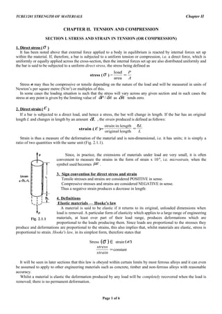
- 1. TCBE1201 STRENGTH OF MATERIALS Chapter II CHAPTER II. TENSION AND COMPRESSION SECTION I. STRESS AND STRAIN IN TENSION (OR COMPRESSION) 1. Direct stress (σ ) It has been noted above that external force applied to a body in equilibrium is reacted by internal forces set up within the material. If, therefore, a bar is subjected to a uniform tension or compression, i.e. a direct force, which is uniformly or equally applied across the cross-section, then the internal forces set up are also distributed uniformly and the bar is said to be subjected to a uniform direct stress, the stress being defined as stress (σ ) = A P = area load Stress σ may thus be compressive or tensile depending on the nature of the load and will be measured in units of Newton’s per square metre (N/m2 ) or multiples of this. In some cases the loading situation is such that the stress will vary across any given section and in such cases the stress at any point is given by the limiting value of AP δδ / as Aδ tends zero. 2. Direct strain (ε ) If a bar is subjected to a direct load, and hence a stress, the bar will change in length. If the bar has an original length L and changes in length by an amount Lδ , the strain produced is defined as follows: strain ( ε )= L Lδ = lengthoriginal lengthinstrain Strain is thus a measure of the deformation of the material and is non-dimensional, i.e. it has units; it is simply a ratio of two quantities with the same unit (Fig. 2.1.1). Since, in practice, the extensions of materials under load are very small, it is often convenient to measure the strains in the form of strain x 10-6 , i.e. microstrain, when the symbol used becomes µε . 3. Sign convention for direct stress and strain Tensile stresses and strains are considered POSITIVE in sense. Compressive stresses and strains are considered NEGATIVE in sense. Thus a negative strain produces a decrease in length: 4. Definitions Elastic materials — Hooke's law A material is said to be elastic if it returns to its original, unloaded dimensions when load is removed. A particular form of elasticity which applies to a large range of engineering materials, at least over part of their load range, produces deformations which are proportional to the loads producing them. Since loads are proportional to the stresses they produce and deformations are proportional to the strains, this also implies that, whilst materials are elastic, stress is proportional to strain. Hooke's law, in its simplest form, therefore states that Stress ∈)(σ strain )(ε = strain stress constant It will be seen in later sections that this law is obeyed within certain limits by most ferrous alloys and it can even be assumed to apply to other engineering materials such as concrete, timber and non-ferrous alloys with reasonable accuracy. Whilst a material is elastic the deformation produced by any load will be completely recovered when the load is removed; there is no permanent deformation. Page 1 of 6
- 2. TCBE1201 STRENGTH OF MATERIALS Chapter II Modulus of elasticity — Young's modulus Within the elastic limits of materials, i.e. within the limits in which Hooke's law applies, it has been shown that = strain stress constant This constant is given the symbol E and termed the modulus of elasticity or Young's modulus. Thus )2.2( )1.2( LA PL L L A P strain stress E δ δ ε σ =÷= == Young's modulus E is generally assumed to be the same in tension or compression and for most engineering materials has a high numerical value. Typically, E = 200 x 109 N/m2 for steel, so that it will be observed from (2.1) that strains are normally very small since E σ ε = (2.3) In most common engineering applications strains do not often exceed 0.001 or 0.1%. The actual value of Young’s modulus for any materials is normally determined by carrying out a standard tensile on a specimen of the material. Poisson's ratio. When a material is subjected to longitudinal deformation then the lateral dimensions also change. The ratio of the lateral strain to longitudinal strain is a constant quantity called the Poisson's ratio and is designated by ν or 1/m. strainalLongitudin strainLateral =ν (2.4) Modulus of rigidity It is defined as the ratio of shearing stress to shearing strain, i.e. γ τ =G (2.5) Factor of safety Because of uncertainties of loading conditions, we introduce a factor of safety, defined as the ratio of the maximum stress to the allowable or working stress. The maximum stress is generally taken as the yield stress. This is also called the ‘ factor of ignorance’ Free body Diagram The free body diagram of an element of a member in equilibrium is the diagram of only that member or element, as if made free from the rest, with all the internal and external forces acting on it. Coefficient of Linear Thermal Expansion Linear thermal strain ( Tε ) due to change in temperature ( T∆ ) is obtained by using this coefficient (α ) TT ∆=αε (2.6) α has units of per degrees Centigrade (or Fahrenheit) 5. Bar of Varying Cross-section Consider a bar of varying circular cross-section as shown in Fig. 2.1.2 Page 2 of 6
- 3. TCBE1201 STRENGTH OF MATERIALS Chapter II 1 2 3 d1 d2 d3 L1 L2 L3 P P Fig. 2.1.2 Bar of varying cross-section. and subjected to axial load P throughout. The area of different cross -sections is: 2 33 2 22 2 11 4 , 4 , 4 dAdAdA πππ === Let 21 , σσ and 3σ be the corresponding stresses, then, 3 3 2 2 1 1 ,, A P A P A P === σσσ The strains become, 3 3 3 2 2 2 1 1 1 ,, EEE σ ε σ ε σ ε === The changes in lengths become, ,,, 333222111 llllll εεε =∆=∆=∆ Total change in length, ++=∆+∆+∆=∆ 33 3 22 2 11 1 321 EA l EA l EA l Pllll or in general, we have ∑= =∆ n i ii i EA l Pl 1 d1P1 1 d2 d3 2 3 P4 P3P2 L1 L2 L3 d1P1 1 d2 d3 2 3 P4P1 P1 - P2 P1 - P2 (P4- P )3 P4 (a) (b) Free body diagrams Fig.2.1.3. Bar of varying cross-section. If the loads in different sections of the bar are different as shown in Fig. 2.1.3 (a), then free body diagrams may be drawn for each section as shown in Fig. 2.1.3 (b), and the net forces acting in each section may be determined. Thus the stresses, strains and total elongation may be determined. Page 3 of 6
- 4. TCBE1201 STRENGTH OF MATERIALS Chapter II ∑= = ∆+∆+∆=∆ =∆=∆=∆ === === n i ii ii EA lP llll llllll EEE A P A P A P 1 321 333222111 3 3 3 2 2 2 1 1 1 3 3 3 2 2 2 1 1 1 ,, ,, ,, εεε σ ε σ ε σ ε σσσ Example 2.1 A mild steel rod 20mm diameter is subjected to an axial pull of 50KN. Determine the tensile stress induced in the rod and the elongation if the unloaded length is 5m. 2 /210 mGNE = . Solution. Given d=20mm ; P=50KN ; l=5m Area of cross-section of the rod 26622 1031410)20( 44 mdA −− ×=×== ππ Stress 2 6 33 /155.159 10314 1051050 mMN A P = × ××× == − σ Elongation mm AE Pl 789.3 1021010314 1051050 96 33 = ××× ××× == − δ Example 2.2 A short hollow cast iron cylinder of wall thickness 10mm is to carry a compressive load of 600KN. Determine the outside diameter of the cylinder if the ultimate crushing stress for material is 2 /540 mKN . Use a factor of safety of 6. Solution. Let 0d be the outside diameter of the cylinder in mm. Then area of cross-section of the cylinder is, { } 25 0 62 0 2 0 10)10(10)20( 4 mdddA −− ×−=×−−= π π Safe load 25 0 10)10( md − ×−=π 3 0 10600)10(900 ×=−×= dπ mmd 2.2220 =∴ Example 2.3 A round bar as shown in Fig.2.1.4 is subjected to an axial tensile load of 100KN. What must be the diameter ‘d’ if the stress there is to be 2 /100 mMN ? Find also the total elongation. 2 /210 mGNE = . Solution. Page 4 of 6
- 5. TCBE1201 STRENGTH OF MATERIALS Chapter II 100KN100KN d 10cm 8cm 15cm10cm 15cm Fig.2.1.4. Stress 2 4 d P π σ = 2 3 6 4 10100 10100 d π × =× ∴ Diameter, mmmd 68.3503568.0 10 4 3 == × = π Total elongation, mm A l A l A l E P l 0745.0 10 1 )80( 4 15.0 )100( 4 15.0 10 10.0 10200 10100 6 22 39 3 2 2 2 2 1 1 = × × + × + × × = ++=∆ − ππ Example 2.4 A steel bar 25mm diameter is loaded as shown in Fig.2.1.5. Determine the stresses in each part and the total elongation. 2 /210 mGNE = . Solution. 50cm 40cm 20cm 40KN 30KN20KN 10KN A B C D Fig.2.1.5 40KN 30KN40KN 20KN A B C D 20KN B 30KN C Fig.2.1.6 Free body diagrams. Area of cross-section, 26622 1087.49010)25( 44 mdA −− ×=××== ππ The free body diagrams for each portion have been shown in Fig.2.1.6. Stress in various parts are: Page 5 of 6
- 6. TCBE1201 STRENGTH OF MATERIALS Chapter II 2 6 3 2 6 3 2 6 3 /166.61 1087.490 1030 /744.40 1087.490 1020 /488.81 1087.490 1040 mMN mMN mMN CD BC AB = × × = = × × = = × × = − − − σ σ σ Total elongation ∑=∆ iilP AE l 1 [ ] mm3298.02.0304.0205.040 102101087.490 10 96 3 =×+×+× ××× = − Page 6 of 6
- 7. TCBE1201 STRENGTH OF MATERIALS Chapter II 2 6 3 2 6 3 2 6 3 /166.61 1087.490 1030 /744.40 1087.490 1020 /488.81 1087.490 1040 mMN mMN mMN CD BC AB = × × = = × × = = × × = − − − σ σ σ Total elongation ∑=∆ iilP AE l 1 [ ] mm3298.02.0304.0205.040 102101087.490 10 96 3 =×+×+× ××× = − Page 6 of 6