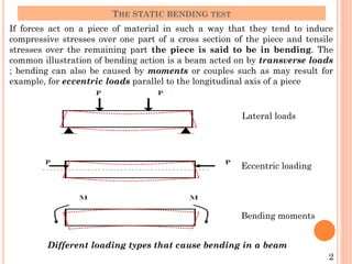
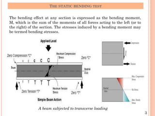
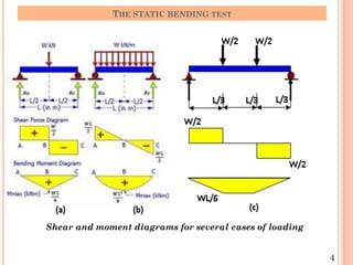
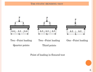
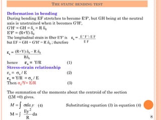
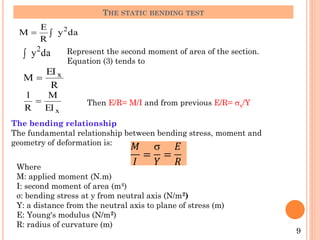
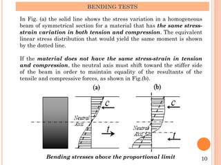
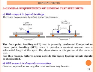
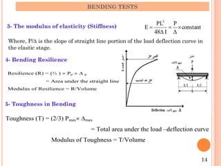
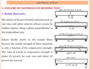
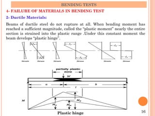
The document describes the static bending test process. It discusses how a beam undergoes bending when subjected to transverse loads, inducing compressive and tensile stresses. The bending moment is expressed as the sum of the moments acting to one side of a beam section. Failure modes depend on the material's ductility - brittle materials rupture suddenly while ductile materials develop plastic hinges. Test variables like loading type, specimen dimensions, and test speed affect bending strength values. Cold bending and hot bending tests evaluate ductility.


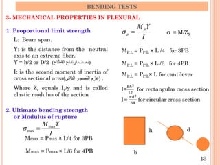


![[Deck] What's New in Spark-Iceberg Integration via DSV2.pptx](https://cdn.slidesharecdn.com/ss_thumbnails/deckwhatsnewinspark-icebergintegrationviadsv2-260210005337-25955b12-thumbnail.jpg?width=640&height=640&fit=bounds)


