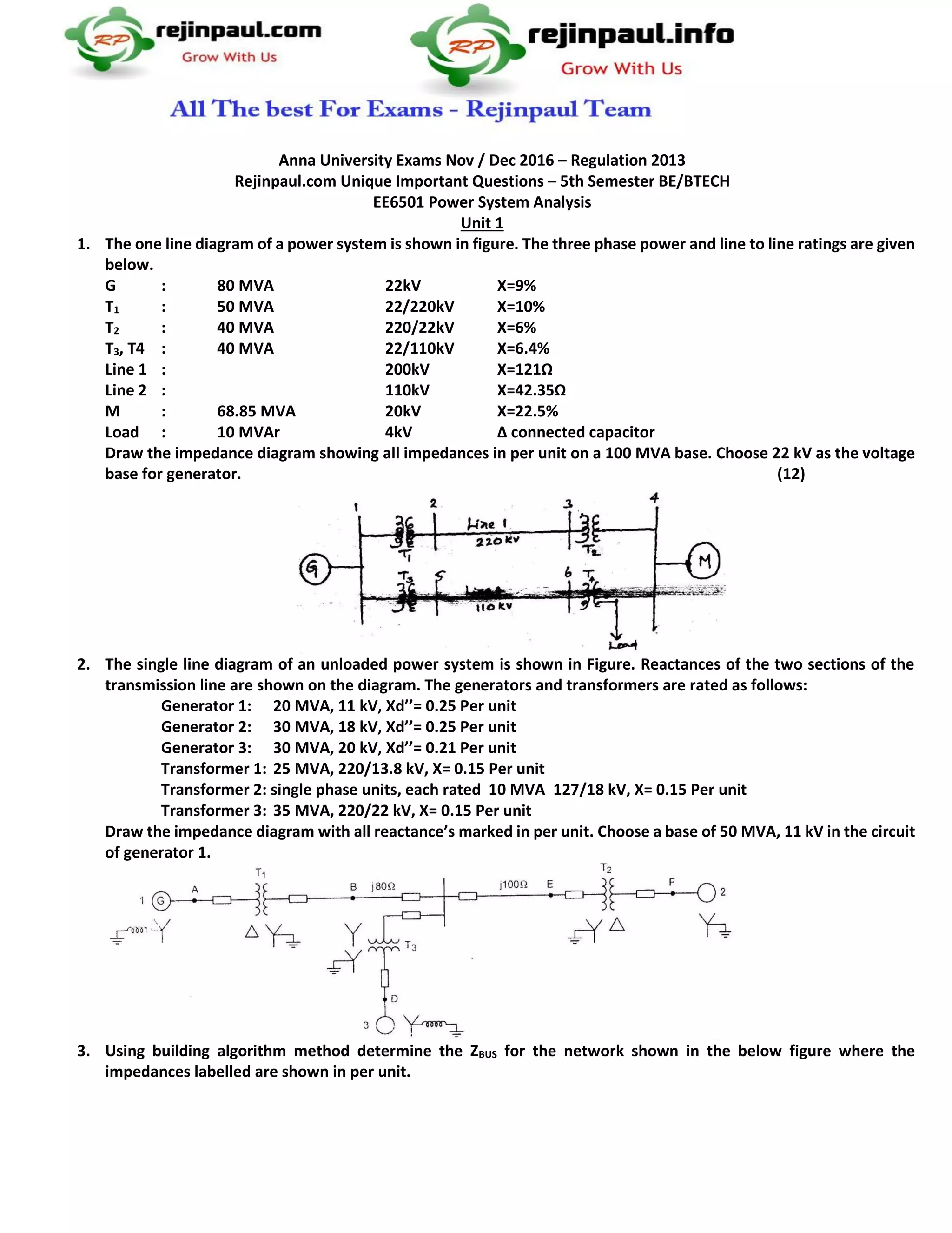
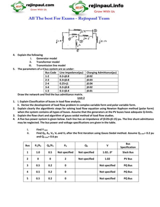
Anna University Exams Nov / Dec 2016 – Regulation 2013
Rejinpaul.com Unique Important Questions – 5th Semester BE/BTECH
EE6501 Power System Analysis
Unit 1
1. The one line diagram of a power system is shown in figure. The three phase power and line to line ratings are given
below.
G : 80 MVA 22kV X=9%
T1 : 50 MVA 22/220kV X=10%
T2 : 40 MVA 220/22kV X=6%
T3, T4 : 40 MVA 22/110kV X=6.4%
Line 1 : 200kV X=121Ω
Line 2 : 110kV X=42.35Ω
M : 68.85 MVA 20kV X=22.5%
Load : 10 MVAr 4kV Δ connected capacitor
Draw the impedance diagram showing all impedances in per unit on a 100 MVA base. Choose 22 kV as the voltage
base for generator. (12)
2. The single line diagram of an unloaded power system is shown in Figure. Reactances of the two sections of the
transmission line are shown on the diagram. The generators and transformers are rated as follows:
Generator 1: 20 MVA, 11 kV, Xd’’= 0.25 Per unit
Generator 2: 30 MVA, 18 kV, Xd’’= 0.25 Per unit
Generator 3: 30 MVA, 20 kV, Xd’’= 0.21 Per unit
Transformer 1: 25 MVA, 220/13.8 kV, X= 0.15 Per unit
Transformer 2: single phase units, each rated 10 MVA 127/18 kV, X= 0.15 Per unit
Transformer 3: 35 MVA, 220/22 kV, X= 0.15 Per unit
Draw the impedance diagram with all reactance’s marked in per unit. Choose a base of 50 MVA, 11 kV in the circuit
of generator 1.
3. Using building algorithm method determine the ZBUS for the network shown in the below figure where the
impedances labelled are shown in per unit.
4. Explain the following
i. Generator model
ii. Transformer model
iii. Transmission line model
5. The parameters of a 4 bus system are as under:
Bus Code Line impedance(pu) Charging Admittance(pu)
1-2 0.2+j0.8 j0.02
2-3 0.3+j0.8 j0.03
2-4 0.25+j1 j0.04
3-4 0.2+j0.8 j0.02
1-3 0.1+j0.4 j0.01
Draw the network and find the bus admittance matrix.
Unit 2
1. i. Explain Classification of buses in load flow analysis.
ii. Derive the development of load flow problem in complex variable form and polar variable form.
2. Explain clearly the algorithmic steps for solving load flow equation using Newton Raphson method (polar form)
when the system contains all types of buses. Assume that the generators at the PV buses have adequate Q-limits.
3. Explain the flow chart and algorithm of gauss seidal method of load flow studies.
4. A five bus power system is given below. Each line has an impedance of (0.05+j0.15) pu. The line shunt admittance
may be neglected. The bus power and voltage specifications are given in the table.
i. Find Y BUS
ii. Find Q2, δ2, V3, V4 and V5 after the first iteration using Gauss Siedal method. Assume Q2 min= 0.2 pu
and Q2 max= 0.6 pu
Bus PL/PD QL/PD PG QG V
Bus
Specification
1 1.0 0.5 Not specified Not specified 1.02∟0o
Slack Bus
2 0 0 2 Not specified 1.02 PV Bus
3 0.5 0.2 0 Not specified PQ Bus
4 0.5 0.2 0 Not specified PQ Bus
5 0.5 0.2 0 Not specified PQ Bus
5. Figure shows the single line diagram of simple three bus power system with generators at buses 1 and 3. The
magnitude of bus 1 is adjusted to 1.05 pu. Voltage magnitude at bus 3 is fixed at 1.04 pu with a real power
generation of 200 MW. A load consisting of 400 MW and 250 MVAR is taken from bus 2. Line impedances are
marked in per unit on a 100 MVA base, and the line charging susceptances are neglected. Obtain the power flow
solution using gauss seidal method up to one iteration including line flows and line losses.
Unit 3
1. For a radial network shown a 3 phase fault occurs at F. determine the fault current and the line voltage at 11 KV
bus under fault conditions
2. Explain the computational procedure of fault analysis using bus building algorithm
3. A synchronous generator and motor are rated 30 MVA , 13.2 kv and both have sub transient reactance of 20%. The
line connecting them has a reactance of 10% on the base of machine rating. The motor is drawing 20000 KW at 0.8
pf lagging and terminal voltage of 12.8 KV. When a symmetrical 3 phase fault occurs at the midpoint of the
transmission line. Find the sub transient current in the generator, motor and fault by using the internal voltage of
the machines.
4. The generators at bus 1 and 3 of the network have impedances of j1.5 .if a 3 phase short circuit fault occurs at bus
3 and at bus 2 when there is no load. Find the initial symmetrical current in fault, line Flows and the post fault
voltages using bus building algorithm.
5. Two generators G1 and G2 opposite to each other are connected to two transformers T1 and T2 respectively through
a transmission line of 60km long, each conductor ha a reactance 0.92Ω/ km . Generator G1 and G2 are identical and
rated as 11kV, 30 MVA and have a transient reactance of 0.3 pu at on MVA base. The transformers T1 and T2 are
identical and are rated 11/66kV, 10 MVA and have a reactance of 0.075 per unit to their own base. The three phase
fault is assumed at point F, which is 25km from generator G1. Find the short circuit current.
Unit 4
1. Draw the sequence network connection for double line to ground fault at any point of in a power system and from
that obtain the expression for the fault current
2. Derive the expression for L-G fault and L-L fault which is grounded through impedance Zf.
3. Discuss in detail about the sequence impedance of and networks of synchronous machine, transformer,
transmission line and loads
4. Derive an expression for the total power in a three phase system in terms of sequence components of voltages and
currents
5. A single line diagram is shown in the fig. generator grounding reactance is 0.5 pu. draw the sequence networks and
calculate the fault current for line to line fault on phase b and c at point Q assume prefault voltage is 1.0 pu
(May/Jun 2013)
Unit 5
1. Describe R.K method of solution of swing equation for SMIB system
2. Derive an expression for critical clearing angle and clearing time
3. Derive the swing equation for a single machine connected to an infinite bus system.
4. State and explain equal area criterion. Indicate how you will apply equal area criterion to find maximum
additional load that can be suddenly added.
5. With a neat flow chart, explain how the transient stability study can be made by modified Euler method.
6. A three generator delivers 1 pu, power to an infinite bus through a transmission network when a fault occurs. The
maximum power which can be transferred during pre fault, during fault and post fault conditions is 1.75 pu, 0.4
pu, 1.25 pu. Find critical clearing angle
7. Derive the power angle equation for a
(i) SMIB System. Also draw the power angle curve.
(ii) A generator having Xd = 0.7 pu delivers rated load at a power factor of 0.8 lagging. Find Pe, Qe, E and
δ.
All the Best for Exams
Questions Are Expected for University Exams This May or may Not Be Asked for Exams
Please do not Copy (or) Republish This Questions, Students if You Find the Same Questions in Other Sources, Kindly report
us to rejinpaulteam@gmail.com

EE6501 Power System Analysis Rejinpaul_Important_Questions

  • 1.
    Anna University ExamsNov / Dec 2016 – Regulation 2013 Rejinpaul.com Unique Important Questions – 5th Semester BE/BTECH EE6501 Power System Analysis Unit 1 1. The one line diagram of a power system is shown in figure. The three phase power and line to line ratings are given below. G : 80 MVA 22kV X=9% T1 : 50 MVA 22/220kV X=10% T2 : 40 MVA 220/22kV X=6% T3, T4 : 40 MVA 22/110kV X=6.4% Line 1 : 200kV X=121Ω Line 2 : 110kV X=42.35Ω M : 68.85 MVA 20kV X=22.5% Load : 10 MVAr 4kV Δ connected capacitor Draw the impedance diagram showing all impedances in per unit on a 100 MVA base. Choose 22 kV as the voltage base for generator. (12) 2. The single line diagram of an unloaded power system is shown in Figure. Reactances of the two sections of the transmission line are shown on the diagram. The generators and transformers are rated as follows: Generator 1: 20 MVA, 11 kV, Xd’’= 0.25 Per unit Generator 2: 30 MVA, 18 kV, Xd’’= 0.25 Per unit Generator 3: 30 MVA, 20 kV, Xd’’= 0.21 Per unit Transformer 1: 25 MVA, 220/13.8 kV, X= 0.15 Per unit Transformer 2: single phase units, each rated 10 MVA 127/18 kV, X= 0.15 Per unit Transformer 3: 35 MVA, 220/22 kV, X= 0.15 Per unit Draw the impedance diagram with all reactance’s marked in per unit. Choose a base of 50 MVA, 11 kV in the circuit of generator 1. 3. Using building algorithm method determine the ZBUS for the network shown in the below figure where the impedances labelled are shown in per unit.
  • 2.
    4. Explain thefollowing i. Generator model ii. Transformer model iii. Transmission line model 5. The parameters of a 4 bus system are as under: Bus Code Line impedance(pu) Charging Admittance(pu) 1-2 0.2+j0.8 j0.02 2-3 0.3+j0.8 j0.03 2-4 0.25+j1 j0.04 3-4 0.2+j0.8 j0.02 1-3 0.1+j0.4 j0.01 Draw the network and find the bus admittance matrix. Unit 2 1. i. Explain Classification of buses in load flow analysis. ii. Derive the development of load flow problem in complex variable form and polar variable form. 2. Explain clearly the algorithmic steps for solving load flow equation using Newton Raphson method (polar form) when the system contains all types of buses. Assume that the generators at the PV buses have adequate Q-limits. 3. Explain the flow chart and algorithm of gauss seidal method of load flow studies. 4. A five bus power system is given below. Each line has an impedance of (0.05+j0.15) pu. The line shunt admittance may be neglected. The bus power and voltage specifications are given in the table. i. Find Y BUS ii. Find Q2, δ2, V3, V4 and V5 after the first iteration using Gauss Siedal method. Assume Q2 min= 0.2 pu and Q2 max= 0.6 pu Bus PL/PD QL/PD PG QG V Bus Specification 1 1.0 0.5 Not specified Not specified 1.02∟0o Slack Bus 2 0 0 2 Not specified 1.02 PV Bus 3 0.5 0.2 0 Not specified PQ Bus 4 0.5 0.2 0 Not specified PQ Bus 5 0.5 0.2 0 Not specified PQ Bus
  • 3.
    5. Figure showsthe single line diagram of simple three bus power system with generators at buses 1 and 3. The magnitude of bus 1 is adjusted to 1.05 pu. Voltage magnitude at bus 3 is fixed at 1.04 pu with a real power generation of 200 MW. A load consisting of 400 MW and 250 MVAR is taken from bus 2. Line impedances are marked in per unit on a 100 MVA base, and the line charging susceptances are neglected. Obtain the power flow solution using gauss seidal method up to one iteration including line flows and line losses. Unit 3 1. For a radial network shown a 3 phase fault occurs at F. determine the fault current and the line voltage at 11 KV bus under fault conditions 2. Explain the computational procedure of fault analysis using bus building algorithm 3. A synchronous generator and motor are rated 30 MVA , 13.2 kv and both have sub transient reactance of 20%. The line connecting them has a reactance of 10% on the base of machine rating. The motor is drawing 20000 KW at 0.8 pf lagging and terminal voltage of 12.8 KV. When a symmetrical 3 phase fault occurs at the midpoint of the transmission line. Find the sub transient current in the generator, motor and fault by using the internal voltage of the machines.
  • 4.
    4. The generatorsat bus 1 and 3 of the network have impedances of j1.5 .if a 3 phase short circuit fault occurs at bus 3 and at bus 2 when there is no load. Find the initial symmetrical current in fault, line Flows and the post fault voltages using bus building algorithm. 5. Two generators G1 and G2 opposite to each other are connected to two transformers T1 and T2 respectively through a transmission line of 60km long, each conductor ha a reactance 0.92Ω/ km . Generator G1 and G2 are identical and rated as 11kV, 30 MVA and have a transient reactance of 0.3 pu at on MVA base. The transformers T1 and T2 are identical and are rated 11/66kV, 10 MVA and have a reactance of 0.075 per unit to their own base. The three phase fault is assumed at point F, which is 25km from generator G1. Find the short circuit current. Unit 4 1. Draw the sequence network connection for double line to ground fault at any point of in a power system and from that obtain the expression for the fault current 2. Derive the expression for L-G fault and L-L fault which is grounded through impedance Zf. 3. Discuss in detail about the sequence impedance of and networks of synchronous machine, transformer, transmission line and loads 4. Derive an expression for the total power in a three phase system in terms of sequence components of voltages and currents 5. A single line diagram is shown in the fig. generator grounding reactance is 0.5 pu. draw the sequence networks and calculate the fault current for line to line fault on phase b and c at point Q assume prefault voltage is 1.0 pu (May/Jun 2013)
  • 5.
    Unit 5 1. DescribeR.K method of solution of swing equation for SMIB system 2. Derive an expression for critical clearing angle and clearing time 3. Derive the swing equation for a single machine connected to an infinite bus system. 4. State and explain equal area criterion. Indicate how you will apply equal area criterion to find maximum additional load that can be suddenly added. 5. With a neat flow chart, explain how the transient stability study can be made by modified Euler method. 6. A three generator delivers 1 pu, power to an infinite bus through a transmission network when a fault occurs. The maximum power which can be transferred during pre fault, during fault and post fault conditions is 1.75 pu, 0.4 pu, 1.25 pu. Find critical clearing angle 7. Derive the power angle equation for a (i) SMIB System. Also draw the power angle curve. (ii) A generator having Xd = 0.7 pu delivers rated load at a power factor of 0.8 lagging. Find Pe, Qe, E and δ. All the Best for Exams Questions Are Expected for University Exams This May or may Not Be Asked for Exams Please do not Copy (or) Republish This Questions, Students if You Find the Same Questions in Other Sources, Kindly report us to rejinpaulteam@gmail.com