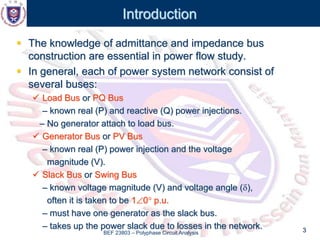
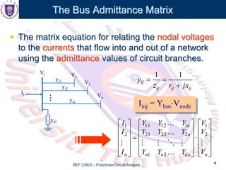
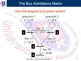
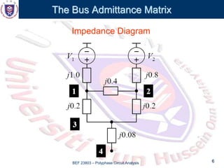
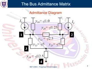
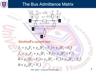
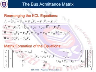
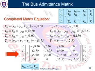
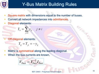
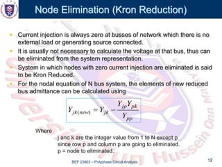
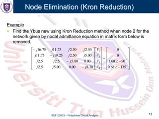
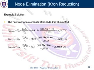
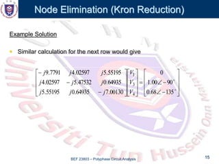
BEF 23803
Polyphase Circuit Analysis
Chapter 5
The Admittance and Impedance Model
BEF 23803 – Polyphase Circuit Analysis 2
Outlines
 Introduction
 The Bus Admittance Matrix
 Power Flow Methods
– Gaussian Elimination
– Kron Reduction
 The Bus Impedance Matrix
BEF 23803 – Polyphase Circuit Analysis 3
Introduction
 The knowledge of admittance and impedance bus
construction are essential in power flow study.
 In general, each of power system network consist of
several buses:
 Load Bus or PQ Bus
– known real (P) and reactive (Q) power injections.
– No generator attach to load bus.
 Generator Bus or PV Bus
– known real (P) power injection and the voltage
magnitude (V).
 Slack Bus or Swing Bus
– known voltage magnitude (V) and voltage angle (),
often it is taken to be 10 p.u.
– must have one generator as the slack bus.
– takes up the power slack due to losses in the network.
BEF 23803 – Polyphase Circuit Analysis 4
The Bus Admittance Matrix
 The matrix equation for relating the nodal voltages
to the currents that flow into and out of a network
using the admittance values of circuit branches.
V1
Vi
Ii
yi1
yi2
yin
…
yi0
V2
Vn
Iinj = YbusVnode
ij
ij
ij
ij
jx
r
z
y



1
1






































n
nn
n
n
n
n
n V
V
V
Y
Y
Y
Y
Y
Y
Y
Y
Y
I
I
I









2
1
2
1
2
22
21
1
12
11
2
1
BEF 23803 – Polyphase Circuit Analysis 5
The Bus Admittance Matrix
One line diagram of a power system
BEF 23803 – Polyphase Circuit Analysis 6
The Bus Admittance Matrix
Impedance Diagram
BEF 23803 – Polyphase Circuit Analysis 7
The Bus Admittance Matrix
Admittance Diagram
BEF 23803 – Polyphase Circuit Analysis 8
The Bus Admittance Matrix
Kirchhoff’s current law:
BEF 23803 – Polyphase Circuit Analysis 9
The Bus Admittance Matrix
Rearranging the KCL Equations:
Matrix Formation of the Equations:
BEF 23803 – Polyphase Circuit Analysis 10
The Bus Admittance Matrix
Completed Matrix Equation:






































n
nn
n
n
n
n
n V
V
V
Y
Y
Y
Y
Y
Y
Y
Y
Y
I
I
I









2
1
2
1
2
22
21
1
12
11
2
1
bus
bus
bus V
Y
I .

BEF 23803 – Polyphase Circuit Analysis 11
Y-Bus Matrix Building Rules
 Square matrix with dimensions equal to the number of buses.
 Convert all network impedances into admittances.
 Diagonal elements:
 Off-diagonal elements:
 Matrix is symmetrical along the leading diagonal.
 When the bus currents are known,
bus
bus
bus I
Y
V 1


BEF 23803 – Polyphase Circuit Analysis 12
Node Elimination (Kron Reduction)
 Current injection is always zero at busses of network which there is no
external load or generating source connected.
 It is usually not necessary to calculate the voltage at that bus, thus can
be eliminated from the system representation.
 System in which nodes with zero current injection are eliminated is said
to be Kron Reduced.
 For the nodal equation of N bus system, the elements of new reduced
bus admittance can be calculated using
pp
pk
jp
jk
new
jk
Y
Y
Y
Y
Y 

)
(
Where
j and k are the integer value from 1 to N except p
since row p and column p are going to eliminated.
p = node to eliminated.
BEF 23803 – Polyphase Circuit Analysis 13
Node Elimination (Kron Reduction)
Example
 Find the Ybus new using Kron Reduction method when node 2 for the
network given by nodal admittance equation in matrix form below is
removed.















































135
68
.
0
90
00
.
1
0
0
30
.
8
00
.
0
00
.
5
5
.
2
00
.
0
80
.
5
5
.
2
5
.
2
00
.
5
50
.
2
25
.
19
75
.
11
50
.
2
50
.
2
75
.
11
75
.
16
4
3
2
1
V
V
V
V
j
j
j
j
j
j
j
j
j
j
j
j
j
j
BEF 23803 – Polyphase Circuit Analysis 14
Node Elimination (Kron Reduction)
Example Solution
 The new row one elements after node 2 is eliminated
pu
j
j
j
j
j
Y
Y
Y
Y
Y new 57792
.
9
25
.
19
)
75
.
11
)(
75
.
11
(
25
.
16
22
21
12
11
)
(
11 







pu
j
j
j
j
j
Y
Y
Y
Y
Y new 02957
.
4
25
.
19
)
50
.
2
)(
75
.
11
(
50
.
2
22
23
12
13
)
(
13 





pu
j
j
j
j
j
Y
Y
Y
Y
Y new 55195
.
5
25
.
19
)
00
.
5
)(
75
.
11
(
5
.
2
22
24
12
14
)
(
14 





BEF 23803 – Polyphase Circuit Analysis 15
Node Elimination (Kron Reduction)
Example Solution
 Similar calculation for the next row would give








































135
68
.
0
90
00
.
1
0
00130
.
7
64935
.
0
55195
.
5
64935
.
0
47532
.
5
02597
.
4
55195
.
5
02597
.
4
7791
.
9
4
3
1
V
V
V
j
j
j
j
j
j
j
j
j

Chapter 5 - The Admittance & Impedance Model.ppt

  • 1.
    BEF 23803 Polyphase CircuitAnalysis Chapter 5 The Admittance and Impedance Model
  • 2.
    BEF 23803 –Polyphase Circuit Analysis 2 Outlines  Introduction  The Bus Admittance Matrix  Power Flow Methods – Gaussian Elimination – Kron Reduction  The Bus Impedance Matrix
  • 3.
    BEF 23803 –Polyphase Circuit Analysis 3 Introduction  The knowledge of admittance and impedance bus construction are essential in power flow study.  In general, each of power system network consist of several buses:  Load Bus or PQ Bus – known real (P) and reactive (Q) power injections. – No generator attach to load bus.  Generator Bus or PV Bus – known real (P) power injection and the voltage magnitude (V).  Slack Bus or Swing Bus – known voltage magnitude (V) and voltage angle (), often it is taken to be 10 p.u. – must have one generator as the slack bus. – takes up the power slack due to losses in the network.
  • 4.
    BEF 23803 –Polyphase Circuit Analysis 4 The Bus Admittance Matrix  The matrix equation for relating the nodal voltages to the currents that flow into and out of a network using the admittance values of circuit branches. V1 Vi Ii yi1 yi2 yin … yi0 V2 Vn Iinj = YbusVnode ij ij ij ij jx r z y    1 1                                       n nn n n n n n V V V Y Y Y Y Y Y Y Y Y I I I          2 1 2 1 2 22 21 1 12 11 2 1
  • 5.
    BEF 23803 –Polyphase Circuit Analysis 5 The Bus Admittance Matrix One line diagram of a power system
  • 6.
    BEF 23803 –Polyphase Circuit Analysis 6 The Bus Admittance Matrix Impedance Diagram
  • 7.
    BEF 23803 –Polyphase Circuit Analysis 7 The Bus Admittance Matrix Admittance Diagram
  • 8.
    BEF 23803 –Polyphase Circuit Analysis 8 The Bus Admittance Matrix Kirchhoff’s current law:
  • 9.
    BEF 23803 –Polyphase Circuit Analysis 9 The Bus Admittance Matrix Rearranging the KCL Equations: Matrix Formation of the Equations:
  • 10.
    BEF 23803 –Polyphase Circuit Analysis 10 The Bus Admittance Matrix Completed Matrix Equation:                                       n nn n n n n n V V V Y Y Y Y Y Y Y Y Y I I I          2 1 2 1 2 22 21 1 12 11 2 1 bus bus bus V Y I . 
  • 11.
    BEF 23803 –Polyphase Circuit Analysis 11 Y-Bus Matrix Building Rules  Square matrix with dimensions equal to the number of buses.  Convert all network impedances into admittances.  Diagonal elements:  Off-diagonal elements:  Matrix is symmetrical along the leading diagonal.  When the bus currents are known, bus bus bus I Y V 1  
  • 12.
    BEF 23803 –Polyphase Circuit Analysis 12 Node Elimination (Kron Reduction)  Current injection is always zero at busses of network which there is no external load or generating source connected.  It is usually not necessary to calculate the voltage at that bus, thus can be eliminated from the system representation.  System in which nodes with zero current injection are eliminated is said to be Kron Reduced.  For the nodal equation of N bus system, the elements of new reduced bus admittance can be calculated using pp pk jp jk new jk Y Y Y Y Y   ) ( Where j and k are the integer value from 1 to N except p since row p and column p are going to eliminated. p = node to eliminated.
  • 13.
    BEF 23803 –Polyphase Circuit Analysis 13 Node Elimination (Kron Reduction) Example  Find the Ybus new using Kron Reduction method when node 2 for the network given by nodal admittance equation in matrix form below is removed.                                                135 68 . 0 90 00 . 1 0 0 30 . 8 00 . 0 00 . 5 5 . 2 00 . 0 80 . 5 5 . 2 5 . 2 00 . 5 50 . 2 25 . 19 75 . 11 50 . 2 50 . 2 75 . 11 75 . 16 4 3 2 1 V V V V j j j j j j j j j j j j j j
  • 14.
    BEF 23803 –Polyphase Circuit Analysis 14 Node Elimination (Kron Reduction) Example Solution  The new row one elements after node 2 is eliminated pu j j j j j Y Y Y Y Y new 57792 . 9 25 . 19 ) 75 . 11 )( 75 . 11 ( 25 . 16 22 21 12 11 ) ( 11         pu j j j j j Y Y Y Y Y new 02957 . 4 25 . 19 ) 50 . 2 )( 75 . 11 ( 50 . 2 22 23 12 13 ) ( 13       pu j j j j j Y Y Y Y Y new 55195 . 5 25 . 19 ) 00 . 5 )( 75 . 11 ( 5 . 2 22 24 12 14 ) ( 14      
  • 15.
    BEF 23803 –Polyphase Circuit Analysis 15 Node Elimination (Kron Reduction) Example Solution  Similar calculation for the next row would give                                         135 68 . 0 90 00 . 1 0 00130 . 7 64935 . 0 55195 . 5 64935 . 0 47532 . 5 02597 . 4 55195 . 5 02597 . 4 7791 . 9 4 3 1 V V V j j j j j j j j j