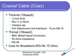
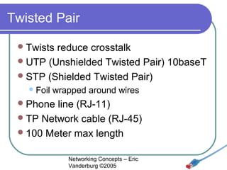
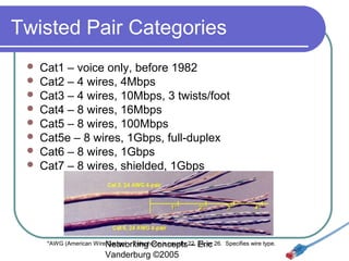
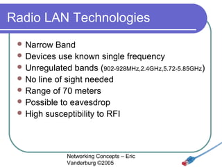
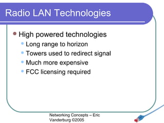
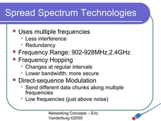
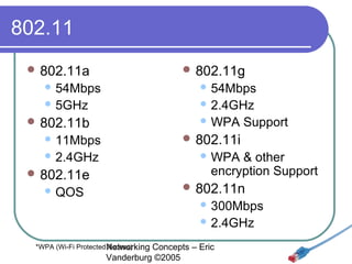
Chapter 3
Networking Media

Networking Concepts – Eric Vanderburg ©2005
Cable Characteristics
 Bandwidth

Rating
 Max Segment Length
 Segments per network
 Devices per segment
 Interference Susceptibility (EMI & RFI)
 Connection Hardware
 Cable Grade (PVC or Plenum Grade Teflon)
 Bend radius
 Cost (Material, Installation, & Maintenance)
Networking Concepts – Eric
Vanderburg ©2005
Signal Degradation
 Reduce
 Do

EMI/RFI

not place copper media next to

 Fluorescent

lights
 Generators/motors
 High-voltage electrical wire
 Proper

installation
 Use quality cable
 Use shielded cabling
 Use repeaters to strengthen signal on long
cable runs
Networking Concepts – Eric
Vanderburg ©2005
Transmission
 Baseband
 Digital
 One

channel
 Use repeaters
 Broadband
 Analog
 Multiple

channels
 Use amplifiers
Networking Concepts – Eric
Vanderburg ©2005
Coaxial Cable (Coax)
 RG-6

- Used for satellite cable
 RG-8 - Thicknet
 RG-11 – 75 ohm, Thicknet, handle higher power
 RG-58 /U - 50 ohm, with a solid copper wire core.
 RG-58 A/U* - 50 ohm, with a stranded wire core.
 RG-58 C/U* - Military version of RG-58 A/U.
 RG-59 - 75 ohm, for broadband transmission such
as cable TV.
 RG-62 - 93 ohm, primarily used for ArcNet.
Networking for Ethernet networks
*Only these are part of the IEEE specificationConcepts – Eric
Vanderburg ©2005
Coaxial Cable (Coax)
 Thicknet

(10base5)

½ inch thick
 RG-11 or RG-8
 Vampire tap
 AUI (Attachment Unit Interface) - 15 pin DB-15


 Thinnet

(10base2)

BNC (British Naval Connector)
 50 ohms impedance
 RG-58


 Coax

for Broadband (RG-59, 75 Ohm)
Networking Concepts – Eric
Vanderburg ©2005
Twisted Pair
 Twists

reduce crosstalk
 UTP (Unshielded Twisted Pair) 10baseT
 STP (Shielded Twisted Pair)
 Foil

wrapped around wires

 Phone

line (RJ-11)
 TP Network cable (RJ-45)
 100 Meter max length
Networking Concepts – Eric
Vanderburg ©2005
Twisted Pair Categories









Cat1 – voice only, before 1982
Cat2 – 4 wires, 4Mbps
Cat3 – 4 wires, 10Mbps, 3 twists/foot
Cat4 – 8 wires, 16Mbps
Cat5 – 8 wires, 100Mbps
Cat5e – 8 wires, 1Gbps, full-duplex
Cat6 – 8 wires, 1Gbps
Cat7 – 8 wires, shielded, 1Gbps

*AWG (American WireNetworking Concepts22, Eric 26. Specifies wire type.
Gauge) – Telephone is usually – 24, or

Vanderburg ©2005
Other Hardware
Wall Plate
Patch Panel

Networking Concepts – Eric
Vanderburg ©2005
Fiber Optic
 Signal

sent by light
 No eavesdropping
 No interference
 Two cables needed for full duplex
 Surrounded by kevlar
 Max length: 2-100 km
 1Gbps & 10Gbps implementations
 Difficult to install
 Expensive (Cable, Install, Maintenance)
Networking Concepts – Eric
Vanderburg ©2005
Fiber Optic Connectors
ST (Straight Tip)

LC (Link
Control)

SC (Straight Connection)

MT-RJ
two cables in one
RJ-45 clone

MIC (Medium Interface Connector)

SMA (Subminiature Type A)

Networking Concepts – Eric
Vanderburg ©2005
Fiber Optic cable types
 Single

mode

Laser based
 Spans longer distance
 One piece of glass
 Core: 2-9 microns


 Multi-mode

LED based
 Shorter distance
 Multiple pieces of glass
 Core: 25-200 microns


View Cables and prices at: http://www.cableorganizer.com/fiber-optic-jumpers/fiber-optic-multimode50.htm
Networking Concepts – Eric

Vanderburg ©2005
Quick Comparison
Type

Length

Bandwidth

UTP

100 meters

10Mbps-1Gbps

Easy

High

Cheapest

STP

100 meters

16Mbps-1Gbps

Moderate

Moderate

Moderate

Thinnet

185 meters

10Mbps

Easy

Moderate

Cheap

Thicknet

500 meters

10Mbps

Hard

Low

Expensive

2-100 kilometers

100Mbps-10Gbps

Moderate

None

Most
Expensive

Fiber

Installation Interference

Networking Concepts – Eric
Vanderburg ©2005

Cost
Cabling Concerns
 Differing

bandwidth requirements
 Building and Fire codes
 Existing setup
 Budget
 Upgradeability, Obsolescence, & TCO

Networking Concepts – Eric
Vanderburg ©2005
Wireless Uses
 Temporary

connections
 Redundant connections
 Network extension
 Roaming
 Access in difficult areas
 Support for handhelds
 Docking
 Peripherals
Networking Concepts – Eric
Vanderburg ©2005
Wireless Networks
 LANs

– 802.11a,b,g
 Extended LANs – Microwave, Satellite
 Mobile – Radio or Cellular
 Provided

by communications carrier

Networking Concepts – Eric
Vanderburg ©2005
Electromagnetic Fundamentals
 Lower

frequency = slower, less data,
longer distance
 Higher frequency = faster, more data,
shorter distance
 Highest frequencies need line of sight &
use tight beams

Networking Concepts – Eric
Vanderburg ©2005
Frequency Ranges
 Radio:

10KHz – 1GHz
 Microwave: 1GHz – 500GHz
 Infrared: 500GHz – 1THz

Networking Concepts – Eric
Vanderburg ©2005
Infrared Technologies
 Line

of Sight
 Reflective (central device)
 Scatter Infrared
 Bounces

signal
 Limited to 30 meters
 Broadband

Optical Telepoint Networks

Networking Concepts – Eric
Vanderburg ©2005
Infrared Transmission


Diffused





Directed





The infrared light transmitted by the sender unit fills the area.
The receiver unit located anywhere in that area can receive
the signal.
The infrared light is focused before transmitting the signal
Increases the transmission speed.

Directed point-to-point



Highest transmission speed
Receiver is aligned with the sender unit. The infrared light is
then transmitted directly to the receiver.

Networking Concepts – Eric
Vanderburg ©2005
Laser Technologies
 Requires

line of sight
 Not vulnerable to visible light
interference

Networking Concepts – Eric
Vanderburg ©2005
Radio LAN Technologies
 Narrow

Band
 Devices use known single frequency
 Unregulated bands (902-928MHz,2.4GHz,5.72-5.85GHz)
 No line of sight needed
 Range of 70 meters
 Possible to eavesdrop
 High susceptibility to RFI

Networking Concepts – Eric
Vanderburg ©2005
Radio LAN Technologies
 High

powered technologies

 Long

range to horizon
 Towers used to redirect signal
 Much more expensive
 FCC licensing required

Networking Concepts – Eric
Vanderburg ©2005
Spread Spectrum Technologies
 Uses

multiple frequencies

Less interference
 Redundancy


 Frequency

Range: 902-928MHz,2.4GHz
 Frequency Hopping
Changes at regular intervals
 Lower bandwidth, more secure


 Direct-sequence

Modulation

Send different data chunks along multiple
frequencies
 Low frequencies (just above noise)


Networking Concepts – Eric
Vanderburg ©2005
802.11
 802.11a

 802.11g

 54Mbps

 54Mbps

 5GHz

 2.4GHz
 WPA

 802.11b
 11Mbps

 802.11i

 2.4GHz

Support

 WPA

& other
encryption Support

 802.11e

 802.11n

 QOS

 300Mbps
 2.4GHz

*WPA (Wi-Fi Protected Networking
Access)

Concepts – Eric
Vanderburg ©2005
Ad Hoc Wireless




Broadcasting/Flooding
Suppose that a mobile user A wants to send data to
another user B in the same area. When the packets
containing the data are ready, user A broadcasts the
packets. On receiving the packets, the receiver checks
the identification on the packet. If that receiver was not
the correct destination, then it rebroadcasts the
packets. This process is repeated until user B gets the
data.
Temporary Infrastructure
In this method, the mobile users set up a temporary
infrastructure (mapping). But this method is
complicated and it introduces overheads. It is useful
only when there is a small number of mobile users.
Networking Concepts – Eric
Vanderburg ©2005
Wireless
 BSA

(Basic Service Area)

 Influence

of the WAPs
 Depends on:
 Power

of the transmitter
 Environment

 BSS

(Basic Service Set)

 Stations

belonging to an AP

Networking Concepts – Eric
Vanderburg ©2005
Wireless Extended LANs
 Connects

LAN segments
 Eliminate leased line costs
 10x cost of leased line
 Work in pairs “half-repeaters”
 Optical

Half-repeaters
 Radio Half-repeaters

Networking Concepts – Eric
Vanderburg ©2005
Wireless Extended LANs
 Short

Range

 1-3

miles
 1-6Mbps
 Spread Spectrum
 Long

Range

 Up

to 25 miles
 2-100Mbps
 Infrared or Laser
Networking Concepts – Eric
Vanderburg ©2005
Microwave Networking
 Higher

transmission than radio
 Line of sight
 FCC approval
 RF Hazard Assessment
(determine RF levels at a site)
 Motorola's WLAN product (ALTAIR)
 Uses

low powered microwave radio signals
 18GHz
Networking Concepts – Eric
Vanderburg ©2005
Microwave Networking
Terrestrial microwave
 Between 2 locations
 Relay towers to cover long distances
 4-6GHz or 21-23GHz
 1-50 miles
 10Mbps
 Vulnerable to weather disturbance
 Satellite microwave
 Propagation delay
 Must have or lease a satellite
(gov’t approval, expensive)
 Global
 Easy to eavesdrop
 11-14GHz
 10Mbps
 Vulnerable to EMI, Jamming, and weather


Networking Concepts – Eric
Vanderburg ©2005
802.16a Wireless MAN
 WiMax

(Worldwide Interoperability for
Microwave Access)
 70Mbps
 30 miles
 Moving car access
 Broadband to distant locations

Networking Concepts – Eric
Vanderburg ©2005
More Microwave technology
 CDPD

(Cellular Digital Packet Data)

 19.2kbps
 Handheld

 Low

connections

orbit satellites

 10bps
 Continental

coverage

Networking Concepts – Eric
Vanderburg ©2005

Networking Concepts Lesson 03 - Media - Eric Vanderburg

  • 1.
    Chapter 3 Networking Media NetworkingConcepts – Eric Vanderburg ©2005
  • 2.
    Cable Characteristics  Bandwidth Rating Max Segment Length  Segments per network  Devices per segment  Interference Susceptibility (EMI & RFI)  Connection Hardware  Cable Grade (PVC or Plenum Grade Teflon)  Bend radius  Cost (Material, Installation, & Maintenance) Networking Concepts – Eric Vanderburg ©2005
  • 3.
    Signal Degradation  Reduce Do EMI/RFI not place copper media next to  Fluorescent lights  Generators/motors  High-voltage electrical wire  Proper installation  Use quality cable  Use shielded cabling  Use repeaters to strengthen signal on long cable runs Networking Concepts – Eric Vanderburg ©2005
  • 4.
    Transmission  Baseband  Digital One channel  Use repeaters  Broadband  Analog  Multiple channels  Use amplifiers Networking Concepts – Eric Vanderburg ©2005
  • 5.
    Coaxial Cable (Coax) RG-6 - Used for satellite cable  RG-8 - Thicknet  RG-11 – 75 ohm, Thicknet, handle higher power  RG-58 /U - 50 ohm, with a solid copper wire core.  RG-58 A/U* - 50 ohm, with a stranded wire core.  RG-58 C/U* - Military version of RG-58 A/U.  RG-59 - 75 ohm, for broadband transmission such as cable TV.  RG-62 - 93 ohm, primarily used for ArcNet. Networking for Ethernet networks *Only these are part of the IEEE specificationConcepts – Eric Vanderburg ©2005
  • 6.
    Coaxial Cable (Coax) Thicknet (10base5) ½ inch thick  RG-11 or RG-8  Vampire tap  AUI (Attachment Unit Interface) - 15 pin DB-15   Thinnet (10base2) BNC (British Naval Connector)  50 ohms impedance  RG-58   Coax for Broadband (RG-59, 75 Ohm) Networking Concepts – Eric Vanderburg ©2005
  • 7.
    Twisted Pair  Twists reducecrosstalk  UTP (Unshielded Twisted Pair) 10baseT  STP (Shielded Twisted Pair)  Foil wrapped around wires  Phone line (RJ-11)  TP Network cable (RJ-45)  100 Meter max length Networking Concepts – Eric Vanderburg ©2005
  • 8.
    Twisted Pair Categories         Cat1– voice only, before 1982 Cat2 – 4 wires, 4Mbps Cat3 – 4 wires, 10Mbps, 3 twists/foot Cat4 – 8 wires, 16Mbps Cat5 – 8 wires, 100Mbps Cat5e – 8 wires, 1Gbps, full-duplex Cat6 – 8 wires, 1Gbps Cat7 – 8 wires, shielded, 1Gbps *AWG (American WireNetworking Concepts22, Eric 26. Specifies wire type. Gauge) – Telephone is usually – 24, or Vanderburg ©2005
  • 9.
    Other Hardware Wall Plate PatchPanel Networking Concepts – Eric Vanderburg ©2005
  • 10.
    Fiber Optic  Signal sentby light  No eavesdropping  No interference  Two cables needed for full duplex  Surrounded by kevlar  Max length: 2-100 km  1Gbps & 10Gbps implementations  Difficult to install  Expensive (Cable, Install, Maintenance) Networking Concepts – Eric Vanderburg ©2005
  • 11.
    Fiber Optic Connectors ST(Straight Tip) LC (Link Control) SC (Straight Connection) MT-RJ two cables in one RJ-45 clone MIC (Medium Interface Connector) SMA (Subminiature Type A) Networking Concepts – Eric Vanderburg ©2005
  • 12.
    Fiber Optic cabletypes  Single mode Laser based  Spans longer distance  One piece of glass  Core: 2-9 microns   Multi-mode LED based  Shorter distance  Multiple pieces of glass  Core: 25-200 microns  View Cables and prices at: http://www.cableorganizer.com/fiber-optic-jumpers/fiber-optic-multimode50.htm Networking Concepts – Eric Vanderburg ©2005
  • 13.
    Quick Comparison Type Length Bandwidth UTP 100 meters 10Mbps-1Gbps Easy High Cheapest STP 100meters 16Mbps-1Gbps Moderate Moderate Moderate Thinnet 185 meters 10Mbps Easy Moderate Cheap Thicknet 500 meters 10Mbps Hard Low Expensive 2-100 kilometers 100Mbps-10Gbps Moderate None Most Expensive Fiber Installation Interference Networking Concepts – Eric Vanderburg ©2005 Cost
  • 14.
    Cabling Concerns  Differing bandwidthrequirements  Building and Fire codes  Existing setup  Budget  Upgradeability, Obsolescence, & TCO Networking Concepts – Eric Vanderburg ©2005
  • 15.
    Wireless Uses  Temporary connections Redundant connections  Network extension  Roaming  Access in difficult areas  Support for handhelds  Docking  Peripherals Networking Concepts – Eric Vanderburg ©2005
  • 16.
    Wireless Networks  LANs –802.11a,b,g  Extended LANs – Microwave, Satellite  Mobile – Radio or Cellular  Provided by communications carrier Networking Concepts – Eric Vanderburg ©2005
  • 17.
    Electromagnetic Fundamentals  Lower frequency= slower, less data, longer distance  Higher frequency = faster, more data, shorter distance  Highest frequencies need line of sight & use tight beams Networking Concepts – Eric Vanderburg ©2005
  • 18.
    Frequency Ranges  Radio: 10KHz– 1GHz  Microwave: 1GHz – 500GHz  Infrared: 500GHz – 1THz Networking Concepts – Eric Vanderburg ©2005
  • 19.
    Infrared Technologies  Line ofSight  Reflective (central device)  Scatter Infrared  Bounces signal  Limited to 30 meters  Broadband Optical Telepoint Networks Networking Concepts – Eric Vanderburg ©2005
  • 20.
    Infrared Transmission  Diffused    Directed    The infraredlight transmitted by the sender unit fills the area. The receiver unit located anywhere in that area can receive the signal. The infrared light is focused before transmitting the signal Increases the transmission speed. Directed point-to-point   Highest transmission speed Receiver is aligned with the sender unit. The infrared light is then transmitted directly to the receiver. Networking Concepts – Eric Vanderburg ©2005
  • 21.
    Laser Technologies  Requires lineof sight  Not vulnerable to visible light interference Networking Concepts – Eric Vanderburg ©2005
  • 22.
    Radio LAN Technologies Narrow Band  Devices use known single frequency  Unregulated bands (902-928MHz,2.4GHz,5.72-5.85GHz)  No line of sight needed  Range of 70 meters  Possible to eavesdrop  High susceptibility to RFI Networking Concepts – Eric Vanderburg ©2005
  • 23.
    Radio LAN Technologies High powered technologies  Long range to horizon  Towers used to redirect signal  Much more expensive  FCC licensing required Networking Concepts – Eric Vanderburg ©2005
  • 24.
    Spread Spectrum Technologies Uses multiple frequencies Less interference  Redundancy   Frequency Range: 902-928MHz,2.4GHz  Frequency Hopping Changes at regular intervals  Lower bandwidth, more secure   Direct-sequence Modulation Send different data chunks along multiple frequencies  Low frequencies (just above noise)  Networking Concepts – Eric Vanderburg ©2005
  • 25.
    802.11  802.11a  802.11g 54Mbps  54Mbps  5GHz  2.4GHz  WPA  802.11b  11Mbps  802.11i  2.4GHz Support  WPA & other encryption Support  802.11e  802.11n  QOS  300Mbps  2.4GHz *WPA (Wi-Fi Protected Networking Access) Concepts – Eric Vanderburg ©2005
  • 26.
    Ad Hoc Wireless   Broadcasting/Flooding Supposethat a mobile user A wants to send data to another user B in the same area. When the packets containing the data are ready, user A broadcasts the packets. On receiving the packets, the receiver checks the identification on the packet. If that receiver was not the correct destination, then it rebroadcasts the packets. This process is repeated until user B gets the data. Temporary Infrastructure In this method, the mobile users set up a temporary infrastructure (mapping). But this method is complicated and it introduces overheads. It is useful only when there is a small number of mobile users. Networking Concepts – Eric Vanderburg ©2005
  • 27.
    Wireless  BSA (Basic ServiceArea)  Influence of the WAPs  Depends on:  Power of the transmitter  Environment  BSS (Basic Service Set)  Stations belonging to an AP Networking Concepts – Eric Vanderburg ©2005
  • 28.
    Wireless Extended LANs Connects LAN segments  Eliminate leased line costs  10x cost of leased line  Work in pairs “half-repeaters”  Optical Half-repeaters  Radio Half-repeaters Networking Concepts – Eric Vanderburg ©2005
  • 29.
    Wireless Extended LANs Short Range  1-3 miles  1-6Mbps  Spread Spectrum  Long Range  Up to 25 miles  2-100Mbps  Infrared or Laser Networking Concepts – Eric Vanderburg ©2005
  • 30.
    Microwave Networking  Higher transmissionthan radio  Line of sight  FCC approval  RF Hazard Assessment (determine RF levels at a site)  Motorola's WLAN product (ALTAIR)  Uses low powered microwave radio signals  18GHz Networking Concepts – Eric Vanderburg ©2005
  • 31.
    Microwave Networking Terrestrial microwave Between 2 locations  Relay towers to cover long distances  4-6GHz or 21-23GHz  1-50 miles  10Mbps  Vulnerable to weather disturbance  Satellite microwave  Propagation delay  Must have or lease a satellite (gov’t approval, expensive)  Global  Easy to eavesdrop  11-14GHz  10Mbps  Vulnerable to EMI, Jamming, and weather  Networking Concepts – Eric Vanderburg ©2005
  • 32.
    802.16a Wireless MAN WiMax (Worldwide Interoperability for Microwave Access)  70Mbps  30 miles  Moving car access  Broadband to distant locations Networking Concepts – Eric Vanderburg ©2005
  • 33.
    More Microwave technology CDPD (Cellular Digital Packet Data)  19.2kbps  Handheld  Low connections orbit satellites  10bps  Continental coverage Networking Concepts – Eric Vanderburg ©2005