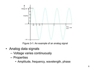
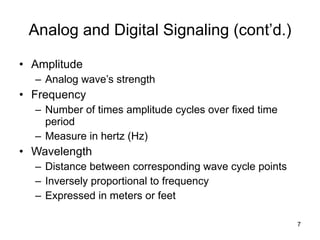
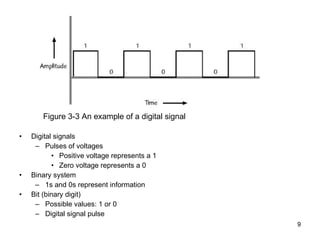
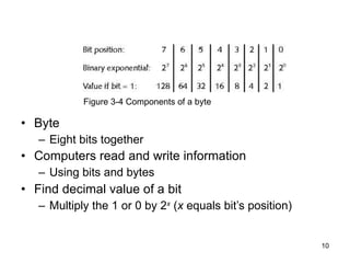
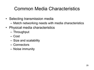
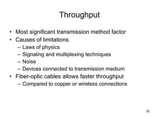
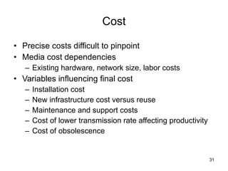
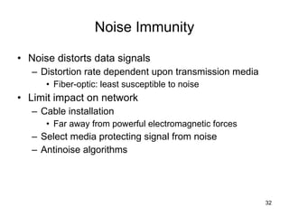
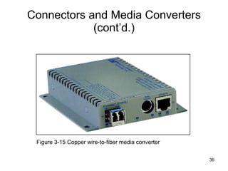
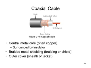
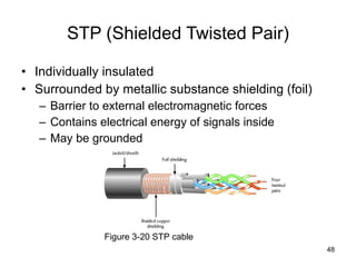
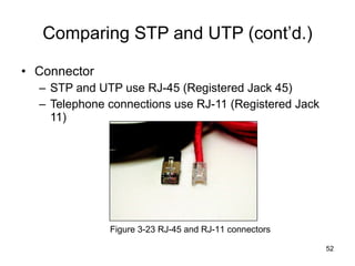
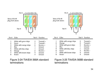
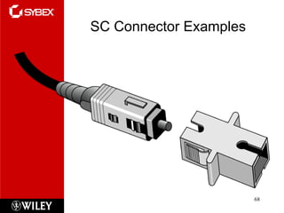
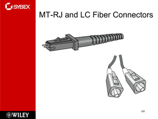
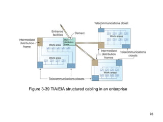
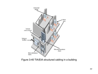
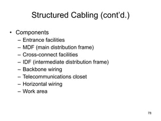
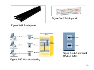
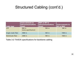
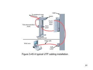
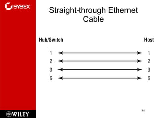
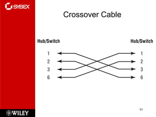
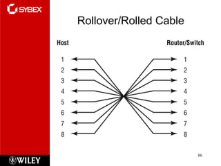
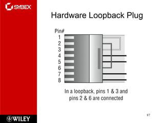
Click to edit Master subtitle style Todd Lammle’s CompTIA Network+ Chapter 3: Networking Topologies, connectors and Wiring Standards Instructor: Mike Qaissaunee
Chapter 3: Objectives 2.1 Categorize standard cable types and their properties Type: CAT3, CAT5, CAT5e, CAT6 STP, UTP Multimode fiber, single-mode fiber Coaxial RG-59 RG-6 Serial Plenum vs. Non-plenum Properties: Transmission speeds Distance Duplex Noise immunity (security, EMI) Frequency 2.2 Identify common connector types RJ-11 RJ-45 BNC SC ST LC RS-232
Chapter 3 Objectives (cont.) 2.4 Given a scenario, differentiate and implement appropriate wiring standards 568A 568B Straight vs. cross-over Rollover Loopback 2.8 Install components of wiring distribution Vertical and horizontal cross connects Patch panels 66 block MDFs IDFs 25 pair 100 pair 110 block Demarc Demarc extension Smart jack Verify wiring installation Verify wiring termination
Transmission Basics Transmitter Issue signals along network medium Transmission Process of transmitting Signal progress after transmitted Transceiver Transmit and receive signals
Analog and Digital Signaling Important data transmission characteristic Signaling type: analog or digital Volt Electrical current pressure Electrical signal strength Directly proportional to voltage Signals Current, light pulses, electromagnetic waves
Analog data signals Voltage varies continuously Properties Amplitude, frequency, wavelength, phase Figure 3-1: An example of an analog signal
Analog and Digital Signaling (cont’d.) Amplitude Analog wave’s strength Frequency Number of times amplitude cycles over fixed time period Measure in hertz (Hz) Wavelength Distance between corresponding wave cycle points Inversely proportional to frequency Expressed in meters or feet
Phase Wave’s progress over time in relationship to fixed point Figure 3-2: Waves with a 90-degree phase difference
Digital signals Pulses of voltages Positive voltage represents a 1 Zero voltage represents a 0 Binary system 1s and 0s represent information Bit (binary digit) Possible values: 1 or 0 Digital signal pulse Figure 3-3 An example of a digital signal
Byte Eight bits together Computers read and write information   Using bits and bytes Find decimal value of a bit Multiply the 1 or 0 by 2 x  ( x  equals bit’s position) Figure 3-4 Components of a byte
Analog and Digital Signaling (cont’d.) Convert byte to decimal number Determine value represented by each bit Add values Convert decimal number to a byte Reverse the process Convert between binary and decimal By hand or calculator
Analog and Digital Signaling (cont’d.) Digital signal benefit over analog signal More reliable Less severe noise interference Digital signal drawback Many pulses required to transmit same information Overhead Nondata information  Required for proper signal routing and interpretation
Data Modulation Data relies on digital transmission Network connection may handle only analog signals Modem Accomplishes translation Modulator/demodulator Data modulation Technology modifying analog signals Make data suitable for carrying over communication path
Data Modulation (cont’d.) Carrier wave Combined with another analog signal Produces unique signal Transmitted from one node to another Preset properties Purpose Convey information Information wave (data wave) Added to carrier wave Modifies one carrier wave property
Data Modulation (cont’d.) Frequency modulation Carrier frequency modified By application of data signal Amplitude modulation Carrier signal amplitude modified By application of data signal
Figure 3-5 Carrier wave modified through frequency modulation
Simplex, Half-Duplex, and Duplex Simplex Signal transmission: one direction Half-duplex transmission Signal transmission: both directions One at a time One communication channel Shared for multiple nodes to exchange information Full-duplex Signals transmission: both directions simultaneously Used on data networks
Multiplexing Multiplexing Multiple signals Travel simultaneously over one medium Subchannels Logical multiple smaller channels Multiplexer (mux) Combines many channel signals Demultiplexer (demux) Separates combined signals Regenerates them
TDM (time division multiplexing) Divides channel into multiple time intervals Figure 3-7 Time division multiplexing
Statistical multiplexing Transmitter assigns slots to nodes According to priority, need More efficient than TDM Figure 3-8 Statistical multiplexing
FDM (frequency division multiplexing) Unique frequency band for each communications subchannel Two types Cellular telephone transmission DSL Internet access Figure 3-9 Frequency division multiplexing
WDM (wavelength division multiplexing) One fiber-optic connection Carries multiple light signals simultaneously DWDM (dense wavelength division multiplexing) Used on most modern fiber-optic networks Extraordinary capacity Figure 3-10 Wavelength division multiplexing
Relationships Between Nodes Point-to-point transmission One transmitter and one receiver Point-to-multipoint transmission One transmitter and multiple receivers Broadcast transmission One transmitter and multiple, undefined receivers Used on wired and wireless networks Simple and quick Nonbroadcast One transmitter and multiple, defined receivers
Throughput and Bandwidth Throughput  Measures amount of data transmitted During given time period Capacity or bandwidth Quantity of bits transmitted per second Bandwidth (strict definition) Measures difference between highest and lowest frequencies medium can transmit Range of frequencies Measured in hertz (Hz)
Baseband and Broadband Baseband transmission Digital signals sent through direct current (DC) pulses applied to wire Requires exclusive use of wire’s capacity Transmit one signal (channel) at a time Example: Ethernet Broadband transmission Signals modulated Radiofrequency (RF) analog waves Uses different frequency ranges Does not encode information as digital pulses
Transmission Flaws Noise Any undesirable influence degrading or distorting signal Types of noise EMI (electromagnetic interference) EMI/RFI (radiofrequency interference) Cross talk NEXT (near end cross talk) Potential cause: improper termination Environmental influences Heat
Transmission Flaws (cont’d.) Attenuation Loss of signal’s strength as it travels away from source Signal boosting technology Analog signals pass through amplifier Noise also amplified Regeneration Digital signals retransmitted in original form Repeater: device regenerating digital signals Amplifiers and repeaters OSI model Physical layer
Transmission Flaws (cont’d.) Latency Delay between signal transmission and receipt Causes Cable length Intervening connectivity device RTT (round trip time) Time for packet to go from sender to receiver, then back from receiver to sender Measured in milliseconds May cause network transmission errors
Common Media Characteristics Selecting transmission media Match networking needs with media characteristics Physical media characteristics Throughput Cost Size and scalability Connectors Noise immunity
Throughput Most significant transmission method factor Causes of limitations Laws of physics Signaling and multiplexing techniques Noise Devices connected to transmission medium Fiber-optic cables allows faster throughput  Compared to copper or wireless connections
Cost Precise costs difficult to pinpoint Media cost dependencies Existing hardware, network size, labor costs Variables influencing final cost Installation cost New infrastructure cost versus reuse Maintenance and support costs Cost of lower transmission rate affecting productivity Cost of obsolescence
Noise Immunity Noise distorts data signals Distortion rate dependent upon transmission media Fiber-optic: least susceptible to noise Limit impact on network Cable installation Far away from powerful electromagnetic forces Select media protecting signal from noise Antinoise algorithms
Size and Scalability Three specifications Maximum nodes per segment Maximum segment length Maximum network length Maximum nodes per segment dependency Attenuation and latency Maximum segment length dependency Attenuation and latency plus segment type
Size and Scalability (cont’d.) Segment types Populated: contains end nodes Unpopulated: No end nodes Link segment Segment length limitation After certain distance, signal loses strength Cannot be accurately interpreted
Connectors and Media Converters Connectors Hardware connecting wire to network device Specific to particular media type Affect costs Installing and maintaining network Ease of adding new segments or nodes Technical expertise required to maintain network Media converter Hardware enabling networks or segments running on different media to interconnect and exchange signals
Connectors and Media Converters (cont’d.) Figure 3-15 Copper wire-to-fiber media converter
Physical Media Let’s take a look at the three types of popular cables used in modern networking designs:  Coaxial Twisted pair Fiber optic
Coax Coaxial  cable ,  referred to as  coax , contains a center conductor made of copper that’s surrounded by a plastic jacket with a braided shield over it.  A plastic such as polyvinyl chloride (PVC, and  Polytetrafluoroethylene  (PTFE ) commonly known as Teflon) covers this metal shield.  The Teflon-type covering is frequently referred to as a  plenum-rated coating , and it’s often mandated by local or municipal fire code when cable is hidden in walls and ceilings.
Coaxial Cable Central metal core (often copper) Surrounded by insulator Braided metal shielding (braiding or shield) Outer cover (sheath or jacket) Figure 3-16 Coaxial cable
Coaxial Cable (cont’d.) High noise resistance Advantage over twisted pair cabling Carry signals farther before amplifier required Disadvantage over twisted pair cabling More expensive Hundreds of specifications RG specification number Differences: shielding and conducting cores Transmission characteristics
Coaxial Cable (cont’d.) Conducting core American Wire Gauge (AWG) size Data networks usage RG-6, Low loss at high frequency for  cable television ,  satellite television  and  cable modems   RG-8, Thicknet ( 10BASE5 )  RG-58, Used for radio communication and  amateur radio , thin Ethernet ( 10BASE2 )  RG-59, Used to carry  baseband  video in  closed-circuit television , previously used for cable television. Generally it has poor shielding but will carry an HQ HD signal or video over short distances.
Coaxial Cable (cont’d.) Figure 3-17 F-type connector  Figure 3-18 BNC Connector
Twisted Pair Cable Color-coded insulated copper wire pairs 0.4 to 0.8 mm diameter Encased in a plastic sheath Figure 3-19 Twisted pair cable
Twisted-Pair Cable Twisted-pair cable consists of multiple individually insulated wires that are twisted together in pairs.  Sometimes a metallic shield is placed around them; hence the name  shielded twisted-pair (STP) .  Cable without outer shielding is called  unshielded twisted-pair (UTP) , and it’s used in twisted-pair Ethernet (10Base-T, 100Base-TX, 1000Base-TX) networks. So why are the wires in this cable type twisted? Because when electromagnetic signals are conducted on copper wires in close proximity—like inside a cable—it causes interference called  crosstalk . Twisting two wires together as a pair minimizes interference and even protects against interference from outside sources.
Unshielded Twisted-pair This cable type is the most common today for the following reasons:  It’s cheaper than other types of cabling. It’s easy to work with. It allows transmission rates that were impossible 10 years ago. UTP cable is rated in these categories: Cat1 Cat2 Cat3 Cat4 Cat5 Cat5e cat6
Twisted Pair Cable (cont’d.) More wire pair twists per foot More resistance to cross talk Higher-quality More expensive Wiring standard specification TIA/EIA 568 Twisted pair wiring types Cat (category) 3, 4, 5, 5e, 6, and 6e, Cat 7 CAT 5 most often used in modern LANs
Twisted Pair Cable (cont’d.) Advantages Relatively inexpensive Flexible Easy installation Spans significant distance before requiring repeater Accommodates several different topologies Handles current faster networking transmission rates Two categories STP (shielded twisted pair) UTP (unshielded twisted pair)
STP (Shielded Twisted Pair) Individually insulated Surrounded by metallic substance shielding (foil) Barrier to external electromagnetic forces Contains electrical energy of signals inside May be grounded Figure 3-20 STP cable
UTP (Unshielded Twisted Pair) (cont’d.) EIA/TIA standards Cat 3 (Category 3) Cat 4 (Category 4) Cat 5 (Category 5) Cat 5e (Enhanced Category 5) Cat 6 (Category 6) Cat 6e (Enhanced Category 6) Cat 7 (Category 7)
Cat 3 ( Category 3) A form of UTP that contains four wire pairs and can carry up to 10 Mbps, with a possible bandwidth of 16 MHz. Cat 3 has typically been used for 10- Mbps Ethernet or 4- Mbps token ring networks.  Cat 4 ( Category 4) A form of UTP that contains four wire pairs and can support up to 16- Mbps throughput. Cat 4 may be used for 16- Mbps token ring or 10- Mbps Ethernet networks. It is guaranteed for data transmission up to 20 MHz and provides more protection against cross talk and attenuation than Cat 1, Cat 2, or Cat 3.  Cat 5 ( Category 5) A form of UTP that contains four wire pairs and supports up to 100- Mbps throughput and a 100- MHz signal rate.  Cat 5e ( Enhanced Category 5) A higher- grade version of Cat 5 wiring that contains high-quality copper, offers a high twist ratio, and uses advanced methods for reducing cross talk . It is capable of transmitting data at speeds of up to 1000 Mbps (1 Gigabit per second).   .
Cat 6 ( Category 6) A twisted pair cable that contains four wire pairs, each wrapped in foil insulation. Additional foil insulation covers the bundle of wire pairs, and a fire- resistant plastic sheath covers the second foil layer. The foil insulation provides excellent resistance to cross talk and enables Cat 6 to support a signaling rate of 250 MHz and at least six times the throughput supported by regular Cat 5.  Category 6 cable was designed to offers higher performance for better transmission of data at speeds up to 1000 Mbps . Category 6A cable is the latest twisted-pair cable type defined in February 2008 under the newest version of the TIA 568-B standard . Category 6A operates at frequencies of up to 500 MHz and can support transmission speeds at 10 Gigabits per second (Gbps).  Cat 7 ( Category 7) A twisted pair cable that contains multiple wire pairs, each separately shielded then surrounded by another layer of shielding within the jacket. Cat 7 can support up to a 1- GHz signal rate. But because of its extra layers, it is less flexible than other forms of twisted pair wiring.
Comparing STP and UTP (cont’d.) Connector STP and UTP use RJ-45 (Registered Jack 45) Telephone connections use RJ-11 (Registered Jack 11) Figure 3-23 RJ-45 and RJ-11 connectors
Terminating Twisted Pair Cable Patch cable Relatively short cable Connectors at both ends Proper cable termination techniques Basic requirement for two nodes to communicate Poor terminations Lead to loss or noise TIA/EIA standards TIA/EIA 568A TIA/EIA 568B
Figure 3-24 TIA/EIA 568A standard terminations Figure 3-25 TIA/EIA 568B standard terminations
Straight-through cable Terminate RJ-45 plugs at both ends identically Crossover cable Transmit and receive wires on one end reversed Figure 3-26 RJ-45 terminations on a crossover cable
Terminating Twisted Pair Cable (cont’d.) Termination tools Wire cutter Wire stripper Crimping tool Figure 3-27 Wire cutter
Terminating Twisted Pair Cable (cont’d.) After making cables Verify data transmit and receive Figure 3-28 Wire stripper Figure 3-29 Crimping tool
Fiber-Optic Cable Fiber-optic cable (fiber) One (or several) glass or plastic fibers at its center (core) Data transmission Pulsing light sent from laser LED (light-emitting diode) through central fibers Cladding Layer of glass or plastic surrounding fibers Different density from glass or plastic in strands Reflects light back to core Allows fiber to bend
Fiber-Optic Cable (cont’d.) Plastic buffer Outside cladding Protects cladding and core Opaque Absorbs any escaping light Kevlar strands (polymeric fiber) surround plastic buffer Plastic sheath covers Kevlar strands
Different varieties Based on intended use and manufacturer Two categories Single-mode Multimode Figure 3-30 A fiber-optic cable
SMF (Single-Mode Fiber) Uses narrow core (< 10 microns in diameter) Laser generated light travels over one path Little reflection Light does not disperse Accommodates Highest bandwidths, longest distances Connects carrier’s two facilities Costs prohibit typical LANs, WANs use
MMF (Multimode Fiber) Uses core with larger diameter than single-mode fiber Common size: 62.5 microns Laser or LED generated light pulses travel at different angles Common uses Cables connecting router to a switch Cables connecting server on network backbone
MMF (Multimode Fiber) (cont’d.) Figure 3-32 Transmission over multimode fiber-optic cable
MMF (Multimode Fiber) (cont’d.) Benefits Extremely high throughput Very high resistance to noise Excellent security Ability to carry signals for much longer distances before requiring repeaters than copper cable Industry standard for high-speed networking Drawback More expensive than twisted pair cable Requires special equipment to splice
MMF (Multimode Fiber) (cont’d.) Throughput Reliable transmission rates Can reach 100 gigabits (or 100,000 megabits) per second per channel Cost Most expensive transmission medium Connectors ST (straight tip) SC (subscriber connector or standard connector) LC (local connector) MT-RJ (mechanical transfer registered jack)
MMF (Multimode Fiber) (cont’d.) Noise immunity Unaffected by EMI Size and scalability Segment lengths vary 150 to 40,000 meters Due primarily to optical loss
ST Connector Examples
SC Connector Examples
MT-RJ and LC Fiber Connectors
Fiber Optic recap Although fiber-optic cable may sound like the solution to many problems, it has pros and cons just like the other cable types.  Here are the pros: Is completely immune to EMI and RFI Can transmit up to 40 kilometers (about 25 miles) And here are the cons: Is difficult to install Is more expensive then twisted-pair Troubleshooting equipment is more expensive then twisted-pair test equipment Is harder to troubleshoot
DTE (Data Terminal Equipment) and DCE (Data Circuit-Terminating Equipment) Connector Cables DTE (data terminal equipment) Any end-user device DCE (data circuit-terminating equipment) Device that processes signals Supplies synchronization clock signal
DTE and DCE Connector Cables (cont’d.) DTE and DCE connections Serial Pulses flow along single transmission line Sequentially Serial cable Carries serial transmissions
DTE and DCE Connector Cables (cont’d.) Figure 3-37 DB-9 connector Figure 3-38 DB-25 connector
DTE and DCE Connector Cables (cont’d.) RS-232 (Recommended Standard 232) EIA/TIA standard Physical layer specification Signal voltage, timing, compatible interface characteristics Connector types RJ-45 connectors, DB-9 connectors, DB-25 connectors RS-232 used between PC and router today RS-232 connections Straight-through, crossover, rollover
Structured Cabling Cable plant Hardware making up enterprise-wide cabling system Standard TIA/EIA joint 568 Commercial Building Wiring Standard
Figure 3-39 TIA/EIA structured cabling in an enterprise
Figure 3-40 TIA/EIA structured cabling in a building
Structured Cabling (cont’d.) Components Entrance facilities MDF (main distribution frame) Cross-connect facilities IDF (intermediate distribution frame) Backbone wiring Telecommunications closet Horizontal wiring Work area
Figure 3-41 Patch panel Figure 3-42 Patch panel Figure 3-43 Horizontal wiring Figure 3-44 A standard TIA/EIA outlet
Structured Cabling (cont’d.) Table 3-2 TIA/EIA specifications for backbone cabling
Figure 3-45 A typical UTP cabling installation
Best Practices for Cable Installation and Management Choosing correct cabling Follow manufacturers’ installation guidelines Follow TIA/EIA standards Network problems Often traced to poor cable installation techniques Installation tips to prevent Physical layer failures
Wiring Standards There are different types of Ethernet wiring standards available: Straight-through cable (586A) Crossover cable (586B) Rolled cable (rollover) Hardware loopback
Straight-through Ethernet Cable
Crossover Cable
Rollover/Rolled Cable
Hardware Loopback Plug
Summary Summary Exam Essentials Section Written Labs Review Questions

Chapter 3

  • 1.
    Click to editMaster subtitle style Todd Lammle’s CompTIA Network+ Chapter 3: Networking Topologies, connectors and Wiring Standards Instructor: Mike Qaissaunee
  • 2.
    Chapter 3: Objectives2.1 Categorize standard cable types and their properties Type: CAT3, CAT5, CAT5e, CAT6 STP, UTP Multimode fiber, single-mode fiber Coaxial RG-59 RG-6 Serial Plenum vs. Non-plenum Properties: Transmission speeds Distance Duplex Noise immunity (security, EMI) Frequency 2.2 Identify common connector types RJ-11 RJ-45 BNC SC ST LC RS-232
  • 3.
    Chapter 3 Objectives(cont.) 2.4 Given a scenario, differentiate and implement appropriate wiring standards 568A 568B Straight vs. cross-over Rollover Loopback 2.8 Install components of wiring distribution Vertical and horizontal cross connects Patch panels 66 block MDFs IDFs 25 pair 100 pair 110 block Demarc Demarc extension Smart jack Verify wiring installation Verify wiring termination
  • 4.
    Transmission Basics TransmitterIssue signals along network medium Transmission Process of transmitting Signal progress after transmitted Transceiver Transmit and receive signals
  • 5.
    Analog and DigitalSignaling Important data transmission characteristic Signaling type: analog or digital Volt Electrical current pressure Electrical signal strength Directly proportional to voltage Signals Current, light pulses, electromagnetic waves
  • 6.
    Analog data signalsVoltage varies continuously Properties Amplitude, frequency, wavelength, phase Figure 3-1: An example of an analog signal
  • 7.
    Analog and DigitalSignaling (cont’d.) Amplitude Analog wave’s strength Frequency Number of times amplitude cycles over fixed time period Measure in hertz (Hz) Wavelength Distance between corresponding wave cycle points Inversely proportional to frequency Expressed in meters or feet
  • 8.
    Phase Wave’s progressover time in relationship to fixed point Figure 3-2: Waves with a 90-degree phase difference
  • 9.
    Digital signals Pulsesof voltages Positive voltage represents a 1 Zero voltage represents a 0 Binary system 1s and 0s represent information Bit (binary digit) Possible values: 1 or 0 Digital signal pulse Figure 3-3 An example of a digital signal
  • 10.
    Byte Eight bitstogether Computers read and write information Using bits and bytes Find decimal value of a bit Multiply the 1 or 0 by 2 x ( x equals bit’s position) Figure 3-4 Components of a byte
  • 11.
    Analog and DigitalSignaling (cont’d.) Convert byte to decimal number Determine value represented by each bit Add values Convert decimal number to a byte Reverse the process Convert between binary and decimal By hand or calculator
  • 12.
    Analog and DigitalSignaling (cont’d.) Digital signal benefit over analog signal More reliable Less severe noise interference Digital signal drawback Many pulses required to transmit same information Overhead Nondata information Required for proper signal routing and interpretation
  • 13.
    Data Modulation Datarelies on digital transmission Network connection may handle only analog signals Modem Accomplishes translation Modulator/demodulator Data modulation Technology modifying analog signals Make data suitable for carrying over communication path
  • 14.
    Data Modulation (cont’d.)Carrier wave Combined with another analog signal Produces unique signal Transmitted from one node to another Preset properties Purpose Convey information Information wave (data wave) Added to carrier wave Modifies one carrier wave property
  • 15.
    Data Modulation (cont’d.)Frequency modulation Carrier frequency modified By application of data signal Amplitude modulation Carrier signal amplitude modified By application of data signal
  • 16.
    Figure 3-5 Carrierwave modified through frequency modulation
  • 17.
    Simplex, Half-Duplex, andDuplex Simplex Signal transmission: one direction Half-duplex transmission Signal transmission: both directions One at a time One communication channel Shared for multiple nodes to exchange information Full-duplex Signals transmission: both directions simultaneously Used on data networks
  • 18.
    Multiplexing Multiplexing Multiplesignals Travel simultaneously over one medium Subchannels Logical multiple smaller channels Multiplexer (mux) Combines many channel signals Demultiplexer (demux) Separates combined signals Regenerates them
  • 19.
    TDM (time divisionmultiplexing) Divides channel into multiple time intervals Figure 3-7 Time division multiplexing
  • 20.
    Statistical multiplexing Transmitterassigns slots to nodes According to priority, need More efficient than TDM Figure 3-8 Statistical multiplexing
  • 21.
    FDM (frequency divisionmultiplexing) Unique frequency band for each communications subchannel Two types Cellular telephone transmission DSL Internet access Figure 3-9 Frequency division multiplexing
  • 22.
    WDM (wavelength divisionmultiplexing) One fiber-optic connection Carries multiple light signals simultaneously DWDM (dense wavelength division multiplexing) Used on most modern fiber-optic networks Extraordinary capacity Figure 3-10 Wavelength division multiplexing
  • 23.
    Relationships Between NodesPoint-to-point transmission One transmitter and one receiver Point-to-multipoint transmission One transmitter and multiple receivers Broadcast transmission One transmitter and multiple, undefined receivers Used on wired and wireless networks Simple and quick Nonbroadcast One transmitter and multiple, defined receivers
  • 24.
    Throughput and BandwidthThroughput Measures amount of data transmitted During given time period Capacity or bandwidth Quantity of bits transmitted per second Bandwidth (strict definition) Measures difference between highest and lowest frequencies medium can transmit Range of frequencies Measured in hertz (Hz)
  • 25.
    Baseband and BroadbandBaseband transmission Digital signals sent through direct current (DC) pulses applied to wire Requires exclusive use of wire’s capacity Transmit one signal (channel) at a time Example: Ethernet Broadband transmission Signals modulated Radiofrequency (RF) analog waves Uses different frequency ranges Does not encode information as digital pulses
  • 26.
    Transmission Flaws NoiseAny undesirable influence degrading or distorting signal Types of noise EMI (electromagnetic interference) EMI/RFI (radiofrequency interference) Cross talk NEXT (near end cross talk) Potential cause: improper termination Environmental influences Heat
  • 27.
    Transmission Flaws (cont’d.)Attenuation Loss of signal’s strength as it travels away from source Signal boosting technology Analog signals pass through amplifier Noise also amplified Regeneration Digital signals retransmitted in original form Repeater: device regenerating digital signals Amplifiers and repeaters OSI model Physical layer
  • 28.
    Transmission Flaws (cont’d.)Latency Delay between signal transmission and receipt Causes Cable length Intervening connectivity device RTT (round trip time) Time for packet to go from sender to receiver, then back from receiver to sender Measured in milliseconds May cause network transmission errors
  • 29.
    Common Media CharacteristicsSelecting transmission media Match networking needs with media characteristics Physical media characteristics Throughput Cost Size and scalability Connectors Noise immunity
  • 30.
    Throughput Most significanttransmission method factor Causes of limitations Laws of physics Signaling and multiplexing techniques Noise Devices connected to transmission medium Fiber-optic cables allows faster throughput Compared to copper or wireless connections
  • 31.
    Cost Precise costsdifficult to pinpoint Media cost dependencies Existing hardware, network size, labor costs Variables influencing final cost Installation cost New infrastructure cost versus reuse Maintenance and support costs Cost of lower transmission rate affecting productivity Cost of obsolescence
  • 32.
    Noise Immunity Noisedistorts data signals Distortion rate dependent upon transmission media Fiber-optic: least susceptible to noise Limit impact on network Cable installation Far away from powerful electromagnetic forces Select media protecting signal from noise Antinoise algorithms
  • 33.
    Size and ScalabilityThree specifications Maximum nodes per segment Maximum segment length Maximum network length Maximum nodes per segment dependency Attenuation and latency Maximum segment length dependency Attenuation and latency plus segment type
  • 34.
    Size and Scalability(cont’d.) Segment types Populated: contains end nodes Unpopulated: No end nodes Link segment Segment length limitation After certain distance, signal loses strength Cannot be accurately interpreted
  • 35.
    Connectors and MediaConverters Connectors Hardware connecting wire to network device Specific to particular media type Affect costs Installing and maintaining network Ease of adding new segments or nodes Technical expertise required to maintain network Media converter Hardware enabling networks or segments running on different media to interconnect and exchange signals
  • 36.
    Connectors and MediaConverters (cont’d.) Figure 3-15 Copper wire-to-fiber media converter
  • 37.
    Physical Media Let’stake a look at the three types of popular cables used in modern networking designs: Coaxial Twisted pair Fiber optic
  • 38.
    Coax Coaxial cable , referred to as coax , contains a center conductor made of copper that’s surrounded by a plastic jacket with a braided shield over it. A plastic such as polyvinyl chloride (PVC, and Polytetrafluoroethylene (PTFE ) commonly known as Teflon) covers this metal shield. The Teflon-type covering is frequently referred to as a plenum-rated coating , and it’s often mandated by local or municipal fire code when cable is hidden in walls and ceilings.
  • 39.
    Coaxial Cable Centralmetal core (often copper) Surrounded by insulator Braided metal shielding (braiding or shield) Outer cover (sheath or jacket) Figure 3-16 Coaxial cable
  • 40.
    Coaxial Cable (cont’d.)High noise resistance Advantage over twisted pair cabling Carry signals farther before amplifier required Disadvantage over twisted pair cabling More expensive Hundreds of specifications RG specification number Differences: shielding and conducting cores Transmission characteristics
  • 41.
    Coaxial Cable (cont’d.)Conducting core American Wire Gauge (AWG) size Data networks usage RG-6, Low loss at high frequency for cable television , satellite television and cable modems RG-8, Thicknet ( 10BASE5 ) RG-58, Used for radio communication and amateur radio , thin Ethernet ( 10BASE2 ) RG-59, Used to carry baseband video in closed-circuit television , previously used for cable television. Generally it has poor shielding but will carry an HQ HD signal or video over short distances.
  • 42.
    Coaxial Cable (cont’d.)Figure 3-17 F-type connector Figure 3-18 BNC Connector
  • 43.
    Twisted Pair CableColor-coded insulated copper wire pairs 0.4 to 0.8 mm diameter Encased in a plastic sheath Figure 3-19 Twisted pair cable
  • 44.
    Twisted-Pair Cable Twisted-paircable consists of multiple individually insulated wires that are twisted together in pairs. Sometimes a metallic shield is placed around them; hence the name shielded twisted-pair (STP) . Cable without outer shielding is called unshielded twisted-pair (UTP) , and it’s used in twisted-pair Ethernet (10Base-T, 100Base-TX, 1000Base-TX) networks. So why are the wires in this cable type twisted? Because when electromagnetic signals are conducted on copper wires in close proximity—like inside a cable—it causes interference called crosstalk . Twisting two wires together as a pair minimizes interference and even protects against interference from outside sources.
  • 45.
    Unshielded Twisted-pair Thiscable type is the most common today for the following reasons: It’s cheaper than other types of cabling. It’s easy to work with. It allows transmission rates that were impossible 10 years ago. UTP cable is rated in these categories: Cat1 Cat2 Cat3 Cat4 Cat5 Cat5e cat6
  • 46.
    Twisted Pair Cable(cont’d.) More wire pair twists per foot More resistance to cross talk Higher-quality More expensive Wiring standard specification TIA/EIA 568 Twisted pair wiring types Cat (category) 3, 4, 5, 5e, 6, and 6e, Cat 7 CAT 5 most often used in modern LANs
  • 47.
    Twisted Pair Cable(cont’d.) Advantages Relatively inexpensive Flexible Easy installation Spans significant distance before requiring repeater Accommodates several different topologies Handles current faster networking transmission rates Two categories STP (shielded twisted pair) UTP (unshielded twisted pair)
  • 48.
    STP (Shielded TwistedPair) Individually insulated Surrounded by metallic substance shielding (foil) Barrier to external electromagnetic forces Contains electrical energy of signals inside May be grounded Figure 3-20 STP cable
  • 49.
    UTP (Unshielded TwistedPair) (cont’d.) EIA/TIA standards Cat 3 (Category 3) Cat 4 (Category 4) Cat 5 (Category 5) Cat 5e (Enhanced Category 5) Cat 6 (Category 6) Cat 6e (Enhanced Category 6) Cat 7 (Category 7)
  • 50.
    Cat 3 (Category 3) A form of UTP that contains four wire pairs and can carry up to 10 Mbps, with a possible bandwidth of 16 MHz. Cat 3 has typically been used for 10- Mbps Ethernet or 4- Mbps token ring networks. Cat 4 ( Category 4) A form of UTP that contains four wire pairs and can support up to 16- Mbps throughput. Cat 4 may be used for 16- Mbps token ring or 10- Mbps Ethernet networks. It is guaranteed for data transmission up to 20 MHz and provides more protection against cross talk and attenuation than Cat 1, Cat 2, or Cat 3. Cat 5 ( Category 5) A form of UTP that contains four wire pairs and supports up to 100- Mbps throughput and a 100- MHz signal rate. Cat 5e ( Enhanced Category 5) A higher- grade version of Cat 5 wiring that contains high-quality copper, offers a high twist ratio, and uses advanced methods for reducing cross talk . It is capable of transmitting data at speeds of up to 1000 Mbps (1 Gigabit per second). .
  • 51.
    Cat 6 (Category 6) A twisted pair cable that contains four wire pairs, each wrapped in foil insulation. Additional foil insulation covers the bundle of wire pairs, and a fire- resistant plastic sheath covers the second foil layer. The foil insulation provides excellent resistance to cross talk and enables Cat 6 to support a signaling rate of 250 MHz and at least six times the throughput supported by regular Cat 5. Category 6 cable was designed to offers higher performance for better transmission of data at speeds up to 1000 Mbps . Category 6A cable is the latest twisted-pair cable type defined in February 2008 under the newest version of the TIA 568-B standard . Category 6A operates at frequencies of up to 500 MHz and can support transmission speeds at 10 Gigabits per second (Gbps). Cat 7 ( Category 7) A twisted pair cable that contains multiple wire pairs, each separately shielded then surrounded by another layer of shielding within the jacket. Cat 7 can support up to a 1- GHz signal rate. But because of its extra layers, it is less flexible than other forms of twisted pair wiring.
  • 52.
    Comparing STP andUTP (cont’d.) Connector STP and UTP use RJ-45 (Registered Jack 45) Telephone connections use RJ-11 (Registered Jack 11) Figure 3-23 RJ-45 and RJ-11 connectors
  • 53.
    Terminating Twisted PairCable Patch cable Relatively short cable Connectors at both ends Proper cable termination techniques Basic requirement for two nodes to communicate Poor terminations Lead to loss or noise TIA/EIA standards TIA/EIA 568A TIA/EIA 568B
  • 54.
    Figure 3-24 TIA/EIA568A standard terminations Figure 3-25 TIA/EIA 568B standard terminations
  • 55.
    Straight-through cable TerminateRJ-45 plugs at both ends identically Crossover cable Transmit and receive wires on one end reversed Figure 3-26 RJ-45 terminations on a crossover cable
  • 56.
    Terminating Twisted PairCable (cont’d.) Termination tools Wire cutter Wire stripper Crimping tool Figure 3-27 Wire cutter
  • 57.
    Terminating Twisted PairCable (cont’d.) After making cables Verify data transmit and receive Figure 3-28 Wire stripper Figure 3-29 Crimping tool
  • 58.
    Fiber-Optic Cable Fiber-opticcable (fiber) One (or several) glass or plastic fibers at its center (core) Data transmission Pulsing light sent from laser LED (light-emitting diode) through central fibers Cladding Layer of glass or plastic surrounding fibers Different density from glass or plastic in strands Reflects light back to core Allows fiber to bend
  • 59.
    Fiber-Optic Cable (cont’d.)Plastic buffer Outside cladding Protects cladding and core Opaque Absorbs any escaping light Kevlar strands (polymeric fiber) surround plastic buffer Plastic sheath covers Kevlar strands
  • 60.
    Different varieties Basedon intended use and manufacturer Two categories Single-mode Multimode Figure 3-30 A fiber-optic cable
  • 61.
    SMF (Single-Mode Fiber)Uses narrow core (< 10 microns in diameter) Laser generated light travels over one path Little reflection Light does not disperse Accommodates Highest bandwidths, longest distances Connects carrier’s two facilities Costs prohibit typical LANs, WANs use
  • 62.
    MMF (Multimode Fiber)Uses core with larger diameter than single-mode fiber Common size: 62.5 microns Laser or LED generated light pulses travel at different angles Common uses Cables connecting router to a switch Cables connecting server on network backbone
  • 63.
    MMF (Multimode Fiber)(cont’d.) Figure 3-32 Transmission over multimode fiber-optic cable
  • 64.
    MMF (Multimode Fiber)(cont’d.) Benefits Extremely high throughput Very high resistance to noise Excellent security Ability to carry signals for much longer distances before requiring repeaters than copper cable Industry standard for high-speed networking Drawback More expensive than twisted pair cable Requires special equipment to splice
  • 65.
    MMF (Multimode Fiber)(cont’d.) Throughput Reliable transmission rates Can reach 100 gigabits (or 100,000 megabits) per second per channel Cost Most expensive transmission medium Connectors ST (straight tip) SC (subscriber connector or standard connector) LC (local connector) MT-RJ (mechanical transfer registered jack)
  • 66.
    MMF (Multimode Fiber)(cont’d.) Noise immunity Unaffected by EMI Size and scalability Segment lengths vary 150 to 40,000 meters Due primarily to optical loss
  • 67.
  • 68.
  • 69.
    MT-RJ and LCFiber Connectors
  • 70.
    Fiber Optic recapAlthough fiber-optic cable may sound like the solution to many problems, it has pros and cons just like the other cable types. Here are the pros: Is completely immune to EMI and RFI Can transmit up to 40 kilometers (about 25 miles) And here are the cons: Is difficult to install Is more expensive then twisted-pair Troubleshooting equipment is more expensive then twisted-pair test equipment Is harder to troubleshoot
  • 71.
    DTE (Data TerminalEquipment) and DCE (Data Circuit-Terminating Equipment) Connector Cables DTE (data terminal equipment) Any end-user device DCE (data circuit-terminating equipment) Device that processes signals Supplies synchronization clock signal
  • 72.
    DTE and DCEConnector Cables (cont’d.) DTE and DCE connections Serial Pulses flow along single transmission line Sequentially Serial cable Carries serial transmissions
  • 73.
    DTE and DCEConnector Cables (cont’d.) Figure 3-37 DB-9 connector Figure 3-38 DB-25 connector
  • 74.
    DTE and DCEConnector Cables (cont’d.) RS-232 (Recommended Standard 232) EIA/TIA standard Physical layer specification Signal voltage, timing, compatible interface characteristics Connector types RJ-45 connectors, DB-9 connectors, DB-25 connectors RS-232 used between PC and router today RS-232 connections Straight-through, crossover, rollover
  • 75.
    Structured Cabling Cableplant Hardware making up enterprise-wide cabling system Standard TIA/EIA joint 568 Commercial Building Wiring Standard
  • 76.
    Figure 3-39 TIA/EIAstructured cabling in an enterprise
  • 77.
    Figure 3-40 TIA/EIAstructured cabling in a building
  • 78.
    Structured Cabling (cont’d.)Components Entrance facilities MDF (main distribution frame) Cross-connect facilities IDF (intermediate distribution frame) Backbone wiring Telecommunications closet Horizontal wiring Work area
  • 79.
    Figure 3-41 Patchpanel Figure 3-42 Patch panel Figure 3-43 Horizontal wiring Figure 3-44 A standard TIA/EIA outlet
  • 80.
    Structured Cabling (cont’d.)Table 3-2 TIA/EIA specifications for backbone cabling
  • 81.
    Figure 3-45 Atypical UTP cabling installation
  • 82.
    Best Practices forCable Installation and Management Choosing correct cabling Follow manufacturers’ installation guidelines Follow TIA/EIA standards Network problems Often traced to poor cable installation techniques Installation tips to prevent Physical layer failures
  • 83.
    Wiring Standards Thereare different types of Ethernet wiring standards available: Straight-through cable (586A) Crossover cable (586B) Rolled cable (rollover) Hardware loopback
  • 84.
  • 85.
  • 86.
  • 87.
  • 88.
    Summary Summary ExamEssentials Section Written Labs Review Questions