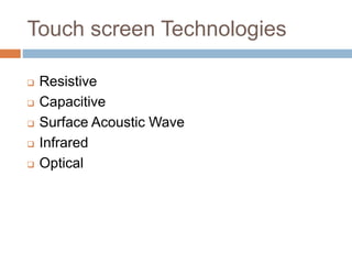
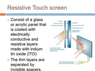
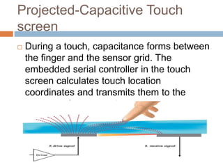
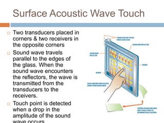
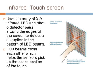
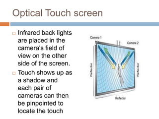
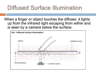
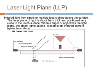
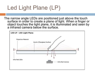
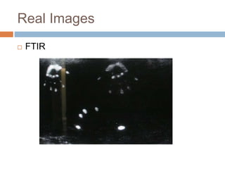
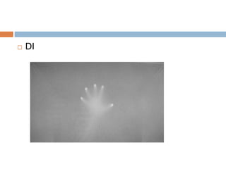
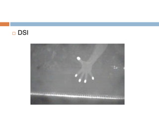
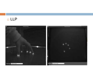
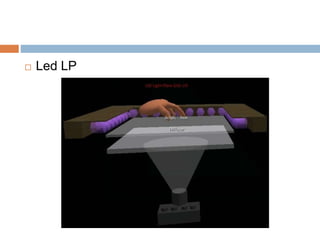
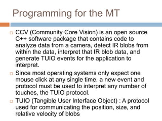
MULTI TOUCH 
INTERACTION 
Parvika Singhal (101103071)
What is Multi-Touch? 
 Ability of a surface to recognize the presence of 
more than one or more than two points of contact 
with the surface 
 India’s First Laser Multi-touch Table is provided by 
Team Zugard 
 The first devices to support Multi-touch were: 
 Mitsubishi Diamond Touch (2001) 
 Apple iPhone (January 9, 2007) 
 Microsoft PixelSense (May 29, 2007) 
 NORTD labs Open Source system CUBIT (multi-touch) 
(2007) 
 ELAN eFinger
MULTI TOUCH DEVICES
Multi-Touch Interaction 
 Human interaction with a computer where 
more than one finger can be used to provide 
input at a time 
 Benefits of multi touch interaction: 
 Natural 
 Simultaneous multi user input
History
Illustration
Touch screen Technologies 
 Resistive 
 Capacitive 
 Surface Acoustic Wave 
 Infrared 
 Optical
Resistive Touch screen 
 Consist of a glass 
or acrylic panel that 
is coated with 
electrically 
conductive and 
resistive layers 
made with indium 
tin oxide (ITO) 
 The thin layers are 
separated by 
invisible spacers.
Projected-Capacitive Touch 
screen 
 During a touch, capacitance forms between 
the finger and the sensor grid. The 
embedded serial controller in the touch 
screen calculates touch location 
coordinates and transmits them to the 
computer for processing.
Surface Acoustic Wave Touch 
 Two transducers placed in 
corners & two receivers in 
the opposite corners 
 Sound wave travels 
parallel to the edges of 
the glass. When the 
sound wave encounters 
the reflectors, the wave is 
transmitted from the 
transducers to the 
receivers. 
 Touch point is detected 
when a drop in the 
amplitude of the sound 
wave occurs.
Infrared Touch screen 
 Uses an array of X-Y 
infrared LED and phot 
o detector pairs 
around the edges of 
the screen to detect a 
disruption in the 
pattern of LED beams. 
 LED beams cross 
each other which 
helps the sensors pick 
up the exact location 
of the touch.
Optical Touch screen 
 Infrared back lights 
are placed in the 
camera's field of 
view on the other 
side of the screen. 
 Touch shows up as 
a shadow and 
each pair of 
cameras can then 
be pinpointed to 
locate the touch
Techniques 
 FTIR : Frustrated Total Internal 
Reflection 
 DI : Diffused Illumination 
 DSI : Diffused Surface Illumination 
 LED LP : Led Laser Plane 
 LLP : Laser Light Plane
PRINCIPLE OF WORKING 
 Mesh of IR is generated on screen 
 Frustration is created on the surface if touched 
 Detected by the camera 
 Blobs (bright luminescent object) are created 
and sent to tracker 
 Tracker communicates with application
FTIR 
Infrared light is placed and directed into the edges of an acrylic 
panel. The light is trapped within the acrylic by “total internal 
reflection”. When a finger touches the acrylic surface, the 
infrared light is “frustrated” causing the light to escape internal 
reflection and scatter downwards where it is seen by an 
infrared camera.
Diffused Illumination 
Infrared light is shined at the screen below/above 
(Rear/Front DI) surface. When an object touches 
the surface it reflects more light than the diffuser or 
objects in the background; the extra light is sensed 
by a camera.
Diffused Surface Illumination 
When a finger or object touches the diffuser, it lights 
up from the infrared light escaping from within and 
is seen by a camera below the surface.
Laser Light Plane (LLP) 
Infrared light from single or multiple lasers shine above the surface. 
The laser plane of light is about 1mm thick and positioned very 
close to the touch surface. When a finger or object hits the light 
plane, the object lights up and is seen by an infrared camera 
below the surface.
Led Light Plane (LP) 
The narrow angle LEDs are positioned just above the touch 
surface in order to create a plane of light. When a finger or 
object touches the light plane, it is illuminated and seen by 
a infrared camera below the surface.
Real Images 
 FTIR
 DI
 DSI
 LLP
 Led LP
Programming for the MT 
 CCV (Community Core Vision) is an open source 
C++ software package that contains code to 
analyze data from a camera, detect IR blobs from 
within the data, interpret that IR blob data, and 
generate TUIO events for the application to 
interpret. 
 Since most operating systems only expect one 
mouse click at any single time, a new event and 
protocol must be used to interpret any number of 
touches, the TUIO protocol. 
 TUIO (Tangible User Interface Object) : A protocol 
used for communicating the position, size, and 
relative velocity of blobs
Multi touch interaction

Multi touch interaction

  • 1.
    MULTI TOUCH INTERACTION Parvika Singhal (101103071)
  • 2.
    What is Multi-Touch?  Ability of a surface to recognize the presence of more than one or more than two points of contact with the surface  India’s First Laser Multi-touch Table is provided by Team Zugard  The first devices to support Multi-touch were:  Mitsubishi Diamond Touch (2001)  Apple iPhone (January 9, 2007)  Microsoft PixelSense (May 29, 2007)  NORTD labs Open Source system CUBIT (multi-touch) (2007)  ELAN eFinger
  • 3.
  • 4.
    Multi-Touch Interaction Human interaction with a computer where more than one finger can be used to provide input at a time  Benefits of multi touch interaction:  Natural  Simultaneous multi user input
  • 5.
  • 6.
  • 7.
    Touch screen Technologies  Resistive  Capacitive  Surface Acoustic Wave  Infrared  Optical
  • 8.
    Resistive Touch screen  Consist of a glass or acrylic panel that is coated with electrically conductive and resistive layers made with indium tin oxide (ITO)  The thin layers are separated by invisible spacers.
  • 9.
    Projected-Capacitive Touch screen  During a touch, capacitance forms between the finger and the sensor grid. The embedded serial controller in the touch screen calculates touch location coordinates and transmits them to the computer for processing.
  • 10.
    Surface Acoustic WaveTouch  Two transducers placed in corners & two receivers in the opposite corners  Sound wave travels parallel to the edges of the glass. When the sound wave encounters the reflectors, the wave is transmitted from the transducers to the receivers.  Touch point is detected when a drop in the amplitude of the sound wave occurs.
  • 11.
    Infrared Touch screen  Uses an array of X-Y infrared LED and phot o detector pairs around the edges of the screen to detect a disruption in the pattern of LED beams.  LED beams cross each other which helps the sensors pick up the exact location of the touch.
  • 12.
    Optical Touch screen  Infrared back lights are placed in the camera's field of view on the other side of the screen.  Touch shows up as a shadow and each pair of cameras can then be pinpointed to locate the touch
  • 13.
    Techniques  FTIR: Frustrated Total Internal Reflection  DI : Diffused Illumination  DSI : Diffused Surface Illumination  LED LP : Led Laser Plane  LLP : Laser Light Plane
  • 14.
    PRINCIPLE OF WORKING  Mesh of IR is generated on screen  Frustration is created on the surface if touched  Detected by the camera  Blobs (bright luminescent object) are created and sent to tracker  Tracker communicates with application
  • 15.
    FTIR Infrared lightis placed and directed into the edges of an acrylic panel. The light is trapped within the acrylic by “total internal reflection”. When a finger touches the acrylic surface, the infrared light is “frustrated” causing the light to escape internal reflection and scatter downwards where it is seen by an infrared camera.
  • 16.
    Diffused Illumination Infraredlight is shined at the screen below/above (Rear/Front DI) surface. When an object touches the surface it reflects more light than the diffuser or objects in the background; the extra light is sensed by a camera.
  • 17.
    Diffused Surface Illumination When a finger or object touches the diffuser, it lights up from the infrared light escaping from within and is seen by a camera below the surface.
  • 18.
    Laser Light Plane(LLP) Infrared light from single or multiple lasers shine above the surface. The laser plane of light is about 1mm thick and positioned very close to the touch surface. When a finger or object hits the light plane, the object lights up and is seen by an infrared camera below the surface.
  • 19.
    Led Light Plane(LP) The narrow angle LEDs are positioned just above the touch surface in order to create a plane of light. When a finger or object touches the light plane, it is illuminated and seen by a infrared camera below the surface.
  • 20.
  • 21.
  • 22.
  • 23.
  • 24.
  • 25.
    Programming for theMT  CCV (Community Core Vision) is an open source C++ software package that contains code to analyze data from a camera, detect IR blobs from within the data, interpret that IR blob data, and generate TUIO events for the application to interpret.  Since most operating systems only expect one mouse click at any single time, a new event and protocol must be used to interpret any number of touches, the TUIO protocol.  TUIO (Tangible User Interface Object) : A protocol used for communicating the position, size, and relative velocity of blobs