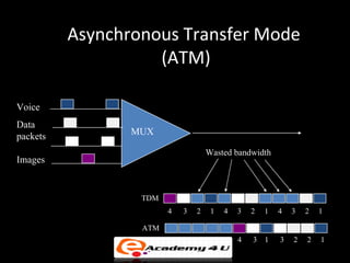
MULTI PROTOCOL LABEL SWITCHING (MPLS)
MPLS Overview

• A forwarding scheme designed to speed up IP
  packet forwarding (RFC 3031)
• Idea: use a fixed length label in the packet
  header to decide packet forwarding
  – Label carried in an MPLS header between the link
    layer header and network layer header
• Support any network layer protocol and link
  layer protocol
MPLS Header Format

• Label: 20-bit label value
• Exp: experimental use
   – Can indicate class of service
• S: bottom of stack indicator
   – 1 for the bottom label, 0 otherwise
• TTL: time to live

              20                 3   1     8

           Label                Exp S      TTL
Why MPLS Protection?

• IP restoration is very slow
  – OSPF, RIP, etc. require a redistribution of
    updated link status information in response to a
    failure.
  – Routing table convergence time on the order of
    seconds.
  – Looping and packet loss can occur during
    convergence
• MPLS enables fast failure restoration
MPLS Protection Approaches
• End-to-End protection
  – A backup LSP is set up in advance from the source
    LSR to the destination LSR of the primary LSP.
     • The backup LSP is link and node disjoint with the primary
       LSP
     • Need reserve resources for the backup LSP
  – Source LSR responsible for restorationsender must
    be notified of the failure
MPLS Protection Approaches
• Local protection
  – When establishing a primary LSP, a backup LSP
    for each possible link or node failure is set up
     • Resources reserved for each backup LSP
  – Failure detecting LSR responsible for switching
    traffic to the backup LSR
  – Faster restoration than end-to-end protection
Local Protection

• Problem: must create a separate set of
  backup LSPs for every primary LSP
• Can a single LSP backup a set of primary
  LSPs?
• Yes! Use MPLS label stacking.
Label Stacking

• A packet may carry multiple labels, organized as a last-
  in-first-out stack
• A label may be added to/removed from the stack at any
  LSR
• Processing always done on the top label
• Allow the aggregation of LSPs into a single LSP for a
  portion of the route, creating a tunnel
   – At the beginning of the tunnel, the LSR assigns the same label
     to packets from different LSPs by pushing the label onto each
     packet’s stack
   – At the end of the tunnel, the LSR pops the top label
Local Protection Using Label
              Stacking

• Bypass tunnel: a LSP used to protect a set
  of LSPs passing over a common facility.
• Label stacking allows different primary
  LSPs to use the same bypass tunnel for
  failure protection.
Local Protection Using Label
                 Stacking

When a failure occurs:
• LSR at the beginning of the tunnel will
   – Switch packets received on the protected LSP x onto the bypass
     tunnel
   – Replace the old label with a new label that will be understood by the
     last node in the bypass tunnel to indicate LSP x
   – Push the bypass tunnel's label onto the label-stack of the redirected
     packets.
• LSR at the end of the tunnel will
   – Pop the bypass tunnel's label
   – Examine the top label to determine the protected LSP that the
     packet is to follow.
Frame Relay
                                 What is it??

• Frame Relay (FR) - public network WAN technology based on
  packet switching
• FR standard defines an interface between an end user and a
  public network. FR is a protocol of 2nd level of OSI model

                      end user

                                          Frame Relay cloud

                           Frame Relay
                           interface


Internal Frame Relay protocol (between switching devices in the cloud) is not
   standardized (probably it will be some day)
Frame Relay
                              What is it about?

• Aim: transport user data between port A and B
         FRAD - Frame Relay
                                                   VC - Virtual Circuit
         Access Device                             PVC - Permanent VC
                               PVC

                  A                                 B
                                     FR switches


• Data is transmitted as variable length frames
  Max. frame length is 4096 bytes (recommended length is 1600
  bytes)
• From users point of view: ports A and B are connected with a
  transparent logical link (virtual circuit - VC)
Frame Relay
                             Standards

• Frame Relay “independent existence”:
   – In 1990 “Group of Four” (DEC, Northern Telecom, Cisco, Stratacom)
     presented FR as an independent standard
   – Later this Frame Relay Forum was established: main standardization body
     for FR
• Standards on which FR is based:
  ANSI T1.602, ANSI T1.606 (Frame Relaying Bearer Service - Architectural
  Framework and Service Description, 1990), ANSI T1.607-1990, ANSI
  T1S1/91-659,ANSI T1.617, ANSI T1.618, CCITT I.122 (Framework for providing
  Additional Packet Mode Bearer Services, 1988), CCITT Q.922, CCITT Q.933
Frame Relay
                     Most important features


•   Based on packet (frame) switching
•   Frames of variable length (up to 4096 bytes, typically 1600 bytes)
•   Connection oriented; only permanent connections - PVCs; switched VCs in
    standard extensions
•   High data rates at user-network interfaces (2Mbps, ultimately up to 45 Mbps)
•   Bandwidth on demand
•   No flow control mechanisms (nearly)
•   No error control (but FCS) or retransmission mechanisms
•   All protocol functions implemented at 2nd level (data link) of OSI model
    No standards for physical interface: can be X.21, V.35, G.703, G.704
Frame Relay
                  Why was it proposed?

• Efficiency: increased demand for high throughput networking
  (X.25 too slow)
• “Bursty applications”: LAN connectivity, Internet, not only
  terminal applications
• Fibre optic lines: low (very, very low) bit error rates
• New, smarter software: applications (or higher level protocols
  like TCP) performing error control, retransmissions; reliable date
  links delivered by higher levels of OSI model
Frame Relay
               Topologies
• star


• full mesh
Frame Relay
                     FR versus leased line

Advantages:
• Decreases number of ports on user devices
   – important for star topology
   – vital for full mesh topologies ( N(N-1)/2 connections, N(N-1) ports)
• Backup lines become public operator responsibility and no
  longer that of an end user; backup connections are switched
  transparently to the user
• More bandwidth is available for traffic peaks; CIR can be more
  expensive than similar leased line; CIR+EIR is much cheaper
Frame Relay
                FR versus leased lines

Advantages:
• Allows to build virtual LANs over whole countries
  (because of mesh topology and ARPs); simplifies routing
• Allows to build private virtual corporate networks; they
  can be separated from the world at the 2nd level of OSI
  model - safety
• A private network can be connected to the Internet in
  only one point: safety and economy
Frame Relay
               FR versus leased lines

Advantages:
• Simplicity of the configuration for the end user
  equipment (not necessarily for the operator…)
• Example: IP over Frame Relay on Cisco IOS

   interface serial 0
       ip address 194.1.1.1 255.255.255.0
       encapsulation frame-relay ietf
       frame-relay lmi-type ansi
Frame Relay
                   FR versus leased lines

Disadvantages:
• Not for delay sensitive applications like: voice, video (though the
   former is sometimes transmitted over FR)
• No guarantee that frames are delivered to the end point; is CIR
   really CIR?

Lots depend on the FR operator; especially overbooking - how
   many times sum of all CIRs extends physical capacity of
   operators connections
Frame Relay
                    How do you really use it

• Rent ports at the operator’s switches (normally together with
  local leased lines and modems); you have to select clock rates
• Ask for PVCs between ports you want; it can be your ports,
  ports on publicly available devices, like border router
• Configure your FRADs - see Cisco example

Isn’t it simple??
ATM
• ATM standard (defined by CCITT) is widely accepted by
  common carriers as mode of operation for
  communication – particularly BISDN.
• ATM is a form of cell switching using small fixed-sized
  packets.

                   Basic ATM Cell Format

      5 Bytes                48 Bytes


     Header                   Payload
Asynchronous Transfer Mode
                    (ATM)

Voice
Data
packets          MUX

                                    Wasted bandwidth
Images


                  TDM
                        4   3   2    1   4   3   2   1   4   3   2   1

                  ATM                                        `
                                             4   3 1     3   2   2   1

Multi protocol label switching (mpls)

  • 1.
    MULTI PROTOCOL LABELSWITCHING (MPLS)
  • 2.
    MPLS Overview • Aforwarding scheme designed to speed up IP packet forwarding (RFC 3031) • Idea: use a fixed length label in the packet header to decide packet forwarding – Label carried in an MPLS header between the link layer header and network layer header • Support any network layer protocol and link layer protocol
  • 3.
    MPLS Header Format •Label: 20-bit label value • Exp: experimental use – Can indicate class of service • S: bottom of stack indicator – 1 for the bottom label, 0 otherwise • TTL: time to live 20 3 1 8 Label Exp S TTL
  • 4.
    Why MPLS Protection? •IP restoration is very slow – OSPF, RIP, etc. require a redistribution of updated link status information in response to a failure. – Routing table convergence time on the order of seconds. – Looping and packet loss can occur during convergence • MPLS enables fast failure restoration
  • 5.
    MPLS Protection Approaches •End-to-End protection – A backup LSP is set up in advance from the source LSR to the destination LSR of the primary LSP. • The backup LSP is link and node disjoint with the primary LSP • Need reserve resources for the backup LSP – Source LSR responsible for restorationsender must be notified of the failure
  • 6.
    MPLS Protection Approaches •Local protection – When establishing a primary LSP, a backup LSP for each possible link or node failure is set up • Resources reserved for each backup LSP – Failure detecting LSR responsible for switching traffic to the backup LSR – Faster restoration than end-to-end protection
  • 7.
    Local Protection • Problem:must create a separate set of backup LSPs for every primary LSP • Can a single LSP backup a set of primary LSPs? • Yes! Use MPLS label stacking.
  • 8.
    Label Stacking • Apacket may carry multiple labels, organized as a last- in-first-out stack • A label may be added to/removed from the stack at any LSR • Processing always done on the top label • Allow the aggregation of LSPs into a single LSP for a portion of the route, creating a tunnel – At the beginning of the tunnel, the LSR assigns the same label to packets from different LSPs by pushing the label onto each packet’s stack – At the end of the tunnel, the LSR pops the top label
  • 9.
    Local Protection UsingLabel Stacking • Bypass tunnel: a LSP used to protect a set of LSPs passing over a common facility. • Label stacking allows different primary LSPs to use the same bypass tunnel for failure protection.
  • 10.
    Local Protection UsingLabel Stacking When a failure occurs: • LSR at the beginning of the tunnel will – Switch packets received on the protected LSP x onto the bypass tunnel – Replace the old label with a new label that will be understood by the last node in the bypass tunnel to indicate LSP x – Push the bypass tunnel's label onto the label-stack of the redirected packets. • LSR at the end of the tunnel will – Pop the bypass tunnel's label – Examine the top label to determine the protected LSP that the packet is to follow.
  • 11.
    Frame Relay What is it?? • Frame Relay (FR) - public network WAN technology based on packet switching • FR standard defines an interface between an end user and a public network. FR is a protocol of 2nd level of OSI model end user Frame Relay cloud Frame Relay interface Internal Frame Relay protocol (between switching devices in the cloud) is not standardized (probably it will be some day)
  • 12.
    Frame Relay What is it about? • Aim: transport user data between port A and B FRAD - Frame Relay VC - Virtual Circuit Access Device PVC - Permanent VC PVC A B FR switches • Data is transmitted as variable length frames Max. frame length is 4096 bytes (recommended length is 1600 bytes) • From users point of view: ports A and B are connected with a transparent logical link (virtual circuit - VC)
  • 13.
    Frame Relay Standards • Frame Relay “independent existence”: – In 1990 “Group of Four” (DEC, Northern Telecom, Cisco, Stratacom) presented FR as an independent standard – Later this Frame Relay Forum was established: main standardization body for FR • Standards on which FR is based: ANSI T1.602, ANSI T1.606 (Frame Relaying Bearer Service - Architectural Framework and Service Description, 1990), ANSI T1.607-1990, ANSI T1S1/91-659,ANSI T1.617, ANSI T1.618, CCITT I.122 (Framework for providing Additional Packet Mode Bearer Services, 1988), CCITT Q.922, CCITT Q.933
  • 14.
    Frame Relay Most important features • Based on packet (frame) switching • Frames of variable length (up to 4096 bytes, typically 1600 bytes) • Connection oriented; only permanent connections - PVCs; switched VCs in standard extensions • High data rates at user-network interfaces (2Mbps, ultimately up to 45 Mbps) • Bandwidth on demand • No flow control mechanisms (nearly) • No error control (but FCS) or retransmission mechanisms • All protocol functions implemented at 2nd level (data link) of OSI model No standards for physical interface: can be X.21, V.35, G.703, G.704
  • 15.
    Frame Relay Why was it proposed? • Efficiency: increased demand for high throughput networking (X.25 too slow) • “Bursty applications”: LAN connectivity, Internet, not only terminal applications • Fibre optic lines: low (very, very low) bit error rates • New, smarter software: applications (or higher level protocols like TCP) performing error control, retransmissions; reliable date links delivered by higher levels of OSI model
  • 16.
    Frame Relay Topologies • star • full mesh
  • 17.
    Frame Relay FR versus leased line Advantages: • Decreases number of ports on user devices – important for star topology – vital for full mesh topologies ( N(N-1)/2 connections, N(N-1) ports) • Backup lines become public operator responsibility and no longer that of an end user; backup connections are switched transparently to the user • More bandwidth is available for traffic peaks; CIR can be more expensive than similar leased line; CIR+EIR is much cheaper
  • 18.
    Frame Relay FR versus leased lines Advantages: • Allows to build virtual LANs over whole countries (because of mesh topology and ARPs); simplifies routing • Allows to build private virtual corporate networks; they can be separated from the world at the 2nd level of OSI model - safety • A private network can be connected to the Internet in only one point: safety and economy
  • 19.
    Frame Relay FR versus leased lines Advantages: • Simplicity of the configuration for the end user equipment (not necessarily for the operator…) • Example: IP over Frame Relay on Cisco IOS interface serial 0 ip address 194.1.1.1 255.255.255.0 encapsulation frame-relay ietf frame-relay lmi-type ansi
  • 20.
    Frame Relay FR versus leased lines Disadvantages: • Not for delay sensitive applications like: voice, video (though the former is sometimes transmitted over FR) • No guarantee that frames are delivered to the end point; is CIR really CIR? Lots depend on the FR operator; especially overbooking - how many times sum of all CIRs extends physical capacity of operators connections
  • 21.
    Frame Relay How do you really use it • Rent ports at the operator’s switches (normally together with local leased lines and modems); you have to select clock rates • Ask for PVCs between ports you want; it can be your ports, ports on publicly available devices, like border router • Configure your FRADs - see Cisco example Isn’t it simple??
  • 22.
    ATM • ATM standard(defined by CCITT) is widely accepted by common carriers as mode of operation for communication – particularly BISDN. • ATM is a form of cell switching using small fixed-sized packets. Basic ATM Cell Format 5 Bytes 48 Bytes Header Payload
  • 23.
    Asynchronous Transfer Mode (ATM) Voice Data packets MUX Wasted bandwidth Images TDM 4 3 2 1 4 3 2 1 4 3 2 1 ATM ` 4 3 1 3 2 2 1

Editor's Notes

  • #4 P529 of Stalling for details of TTL RFC 3032
  • #8 http://www.ietf.org/internet-drafts/draft-ietf-mpls-rsvp-lsp-fastreroute-07.txt Section 4.1