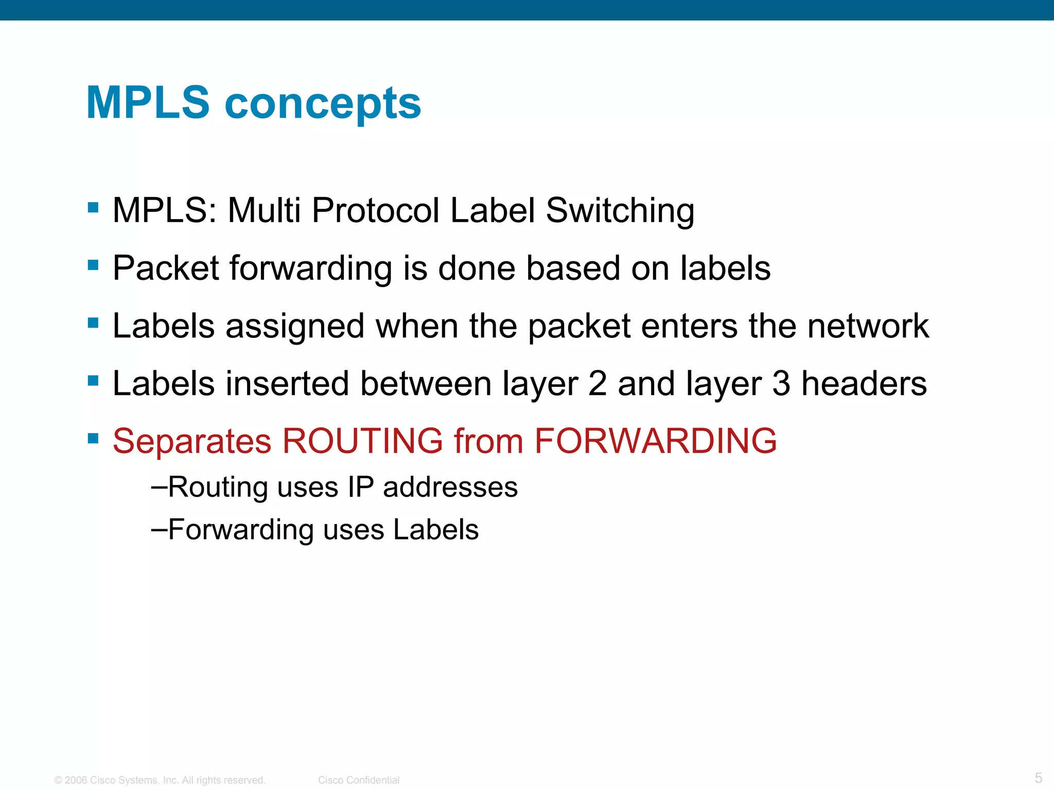
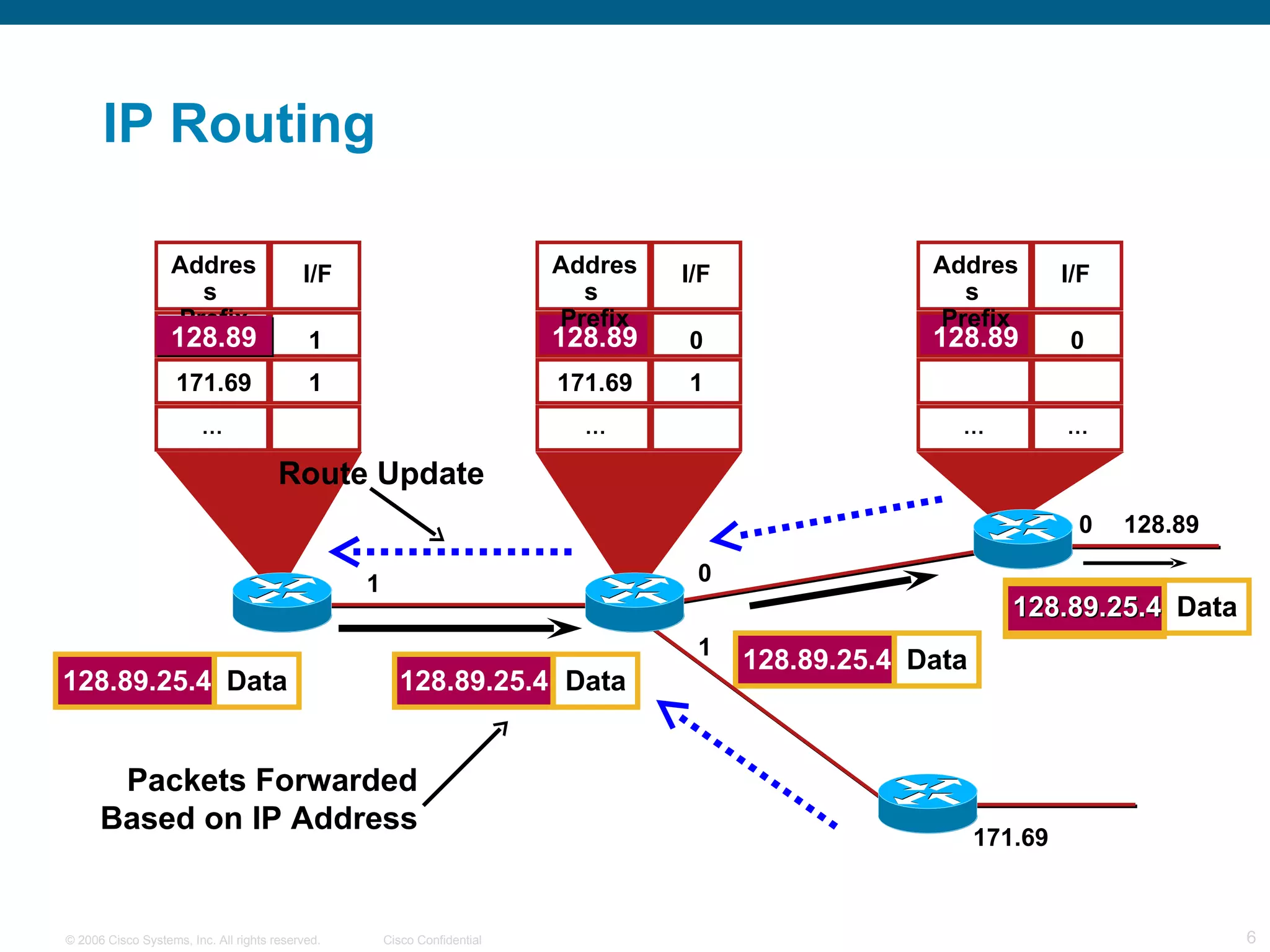
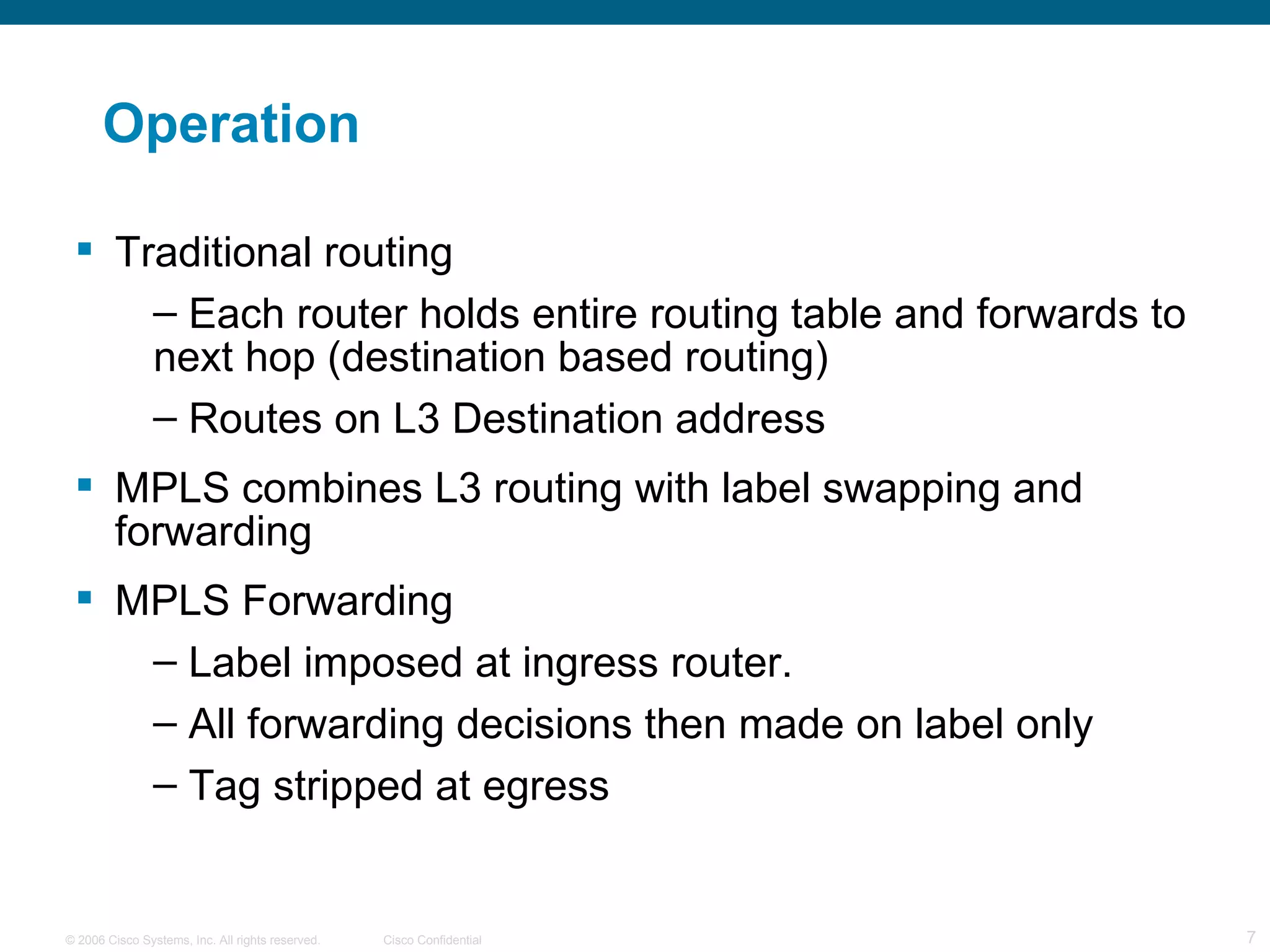
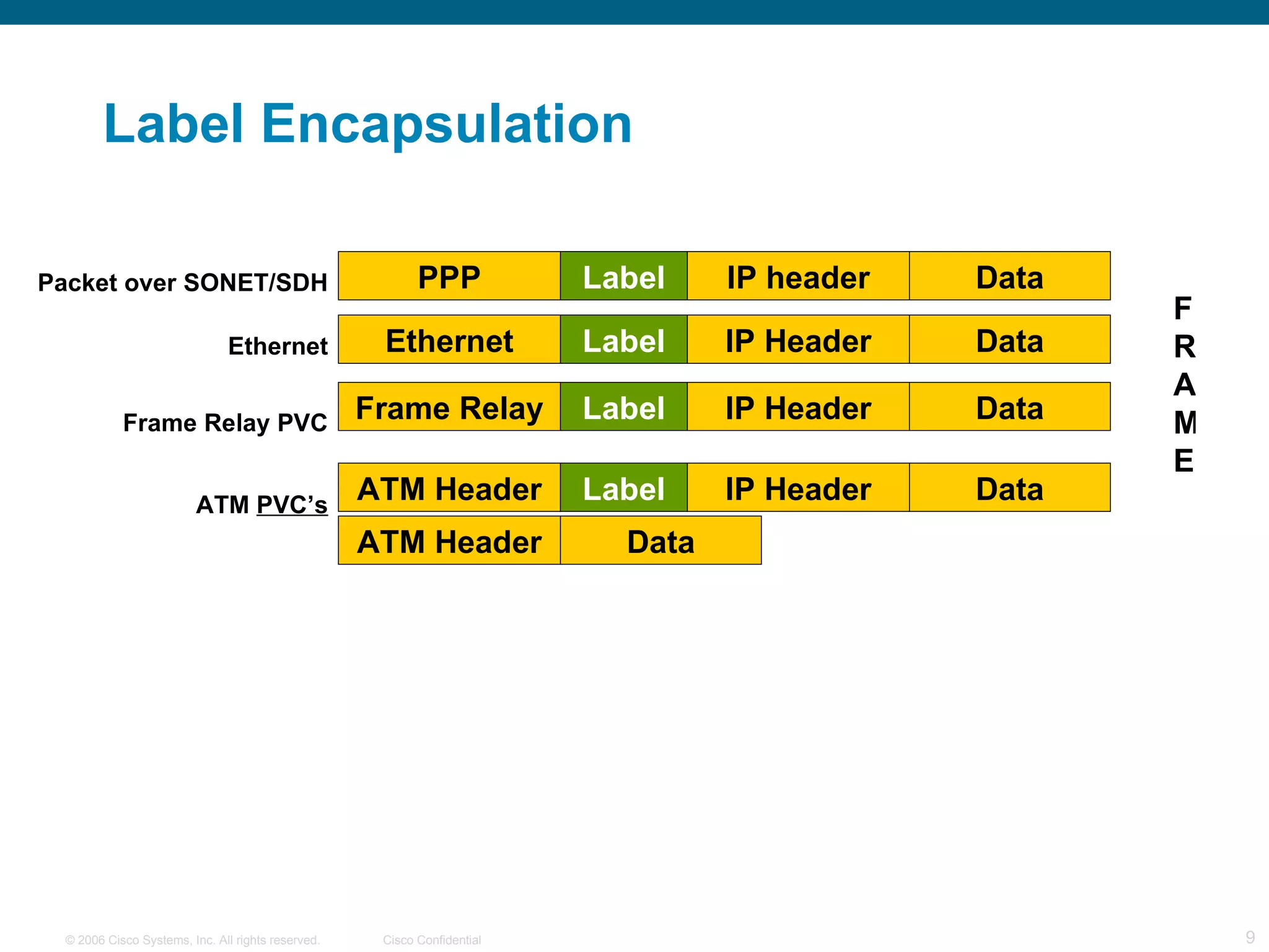
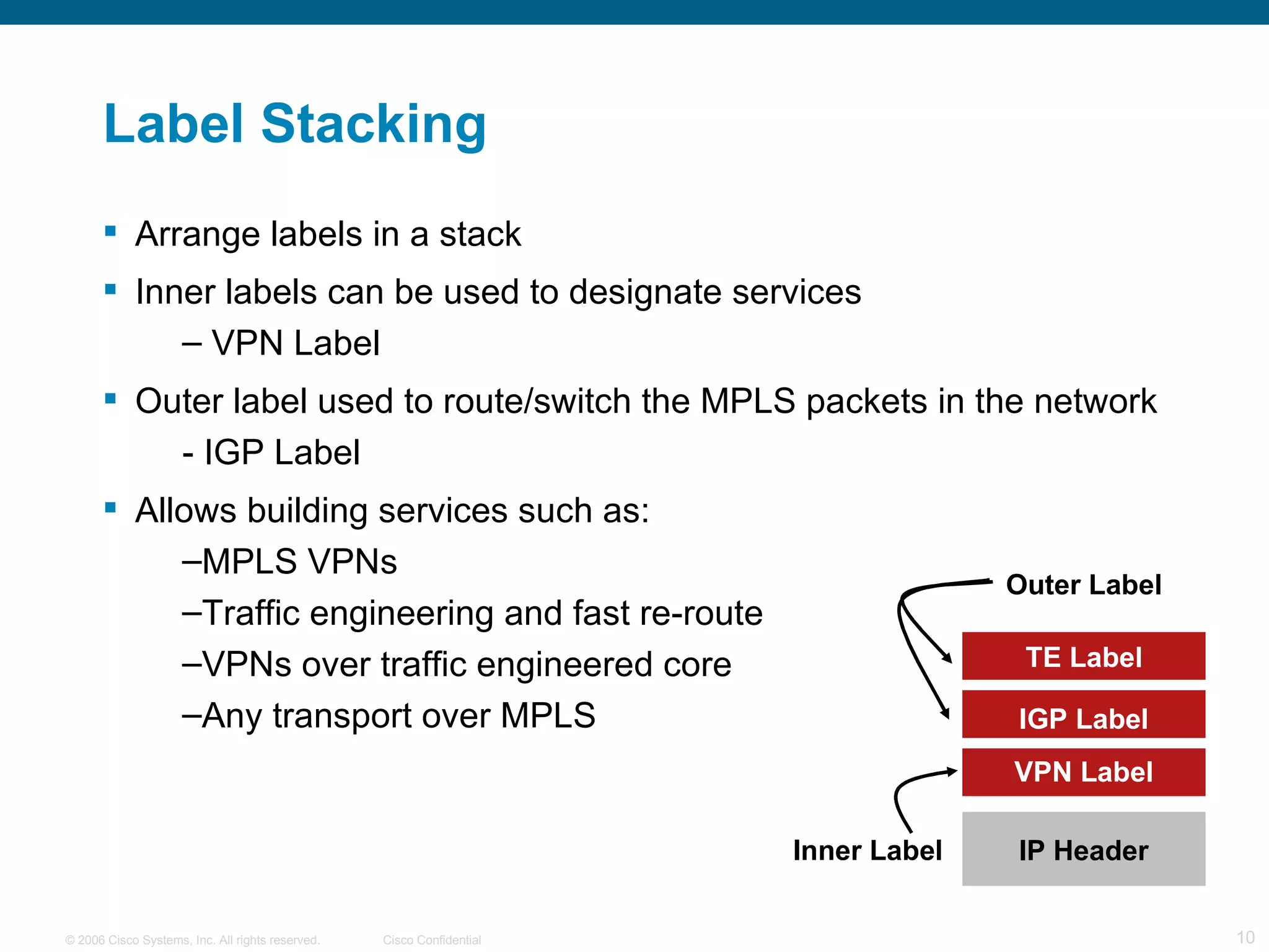
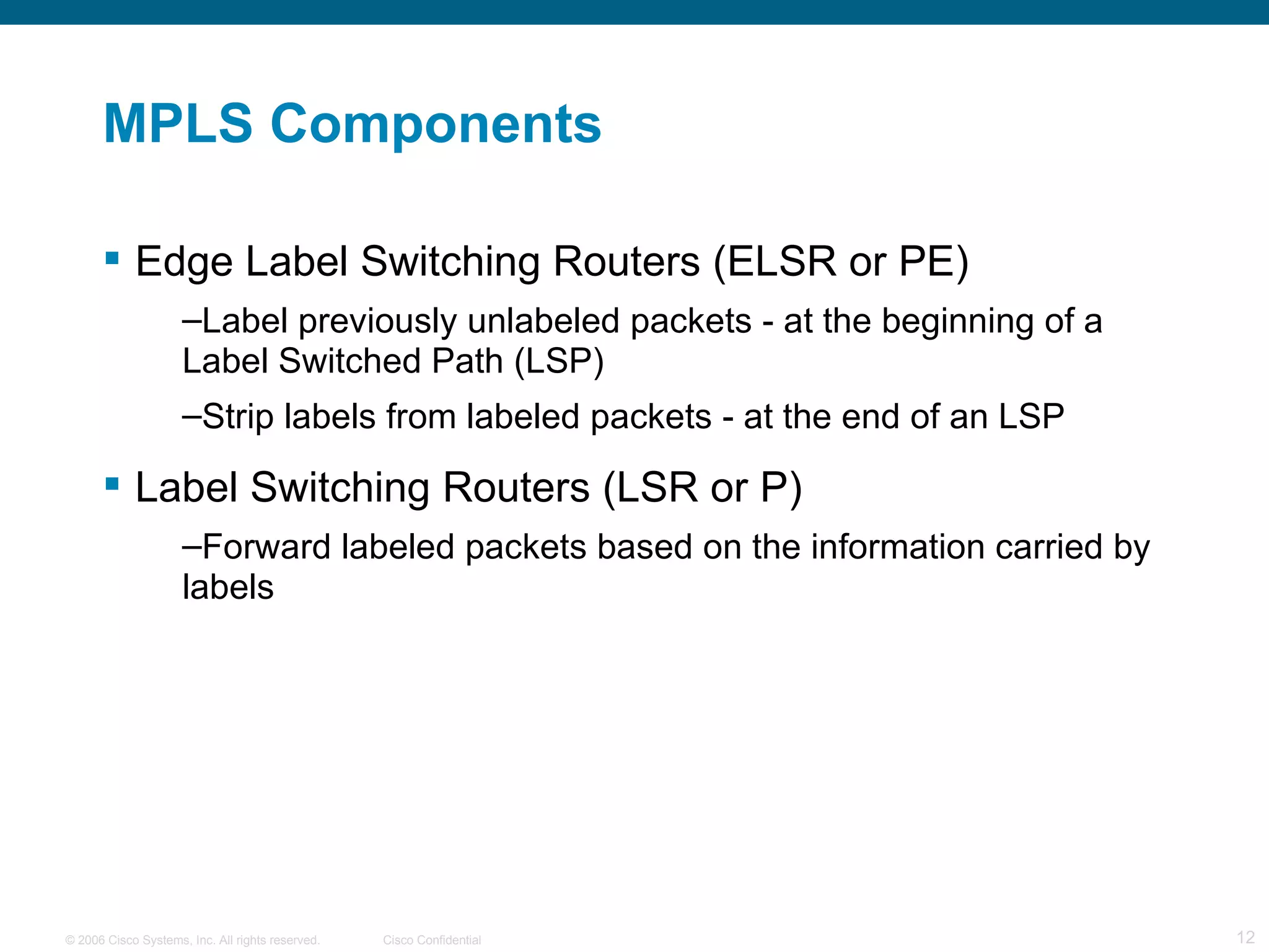
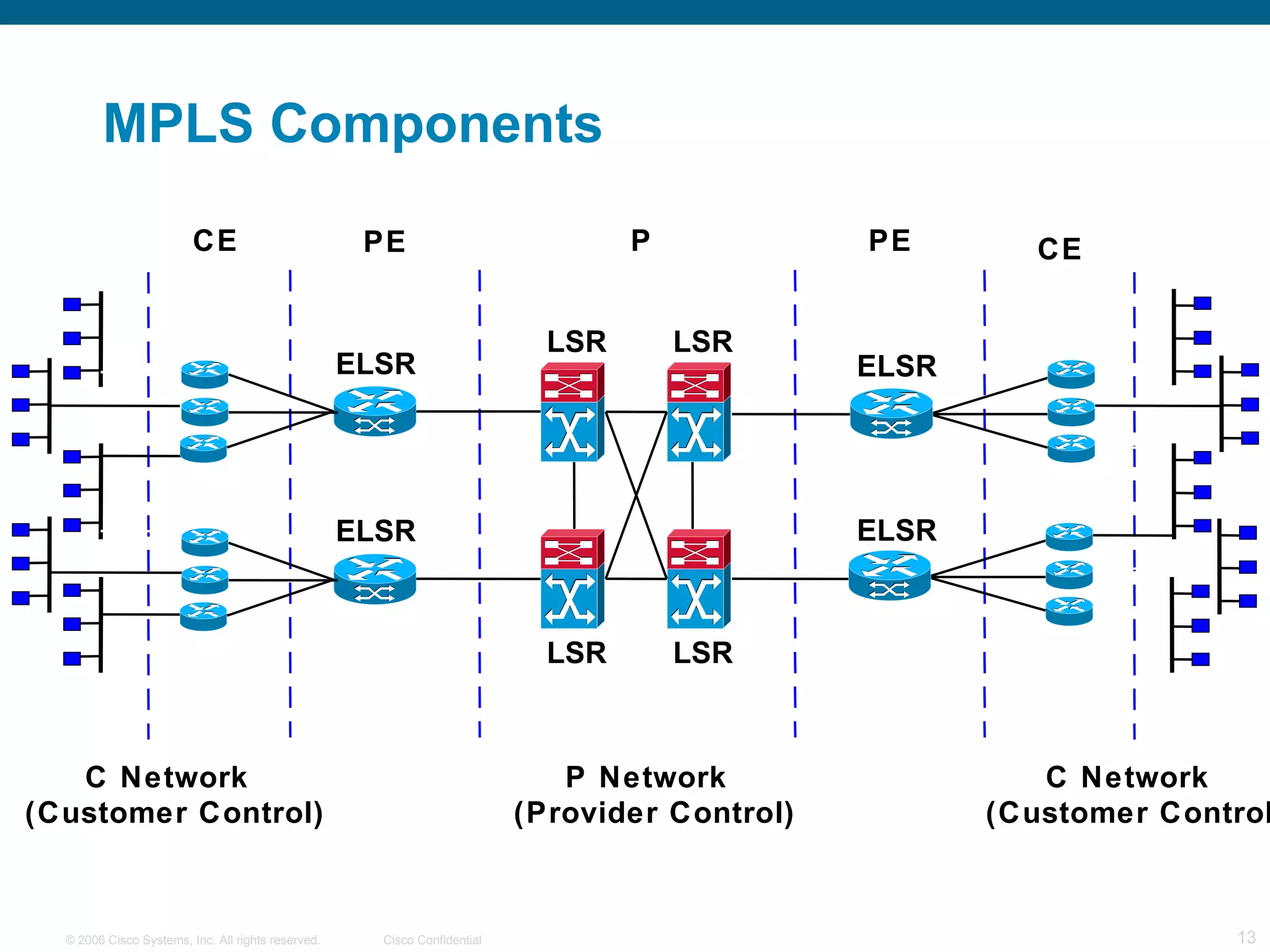
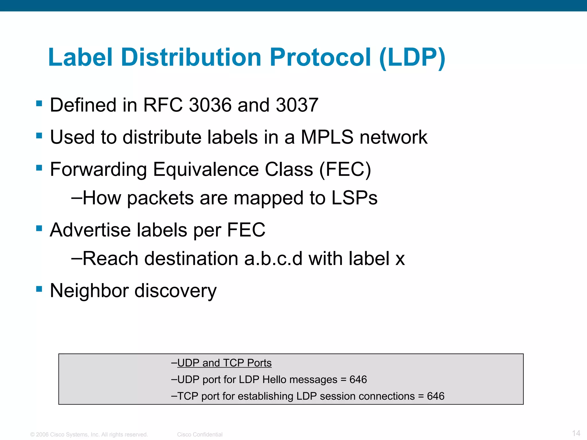
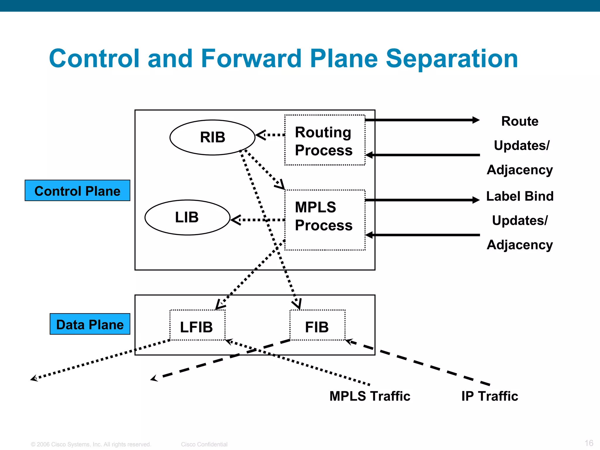
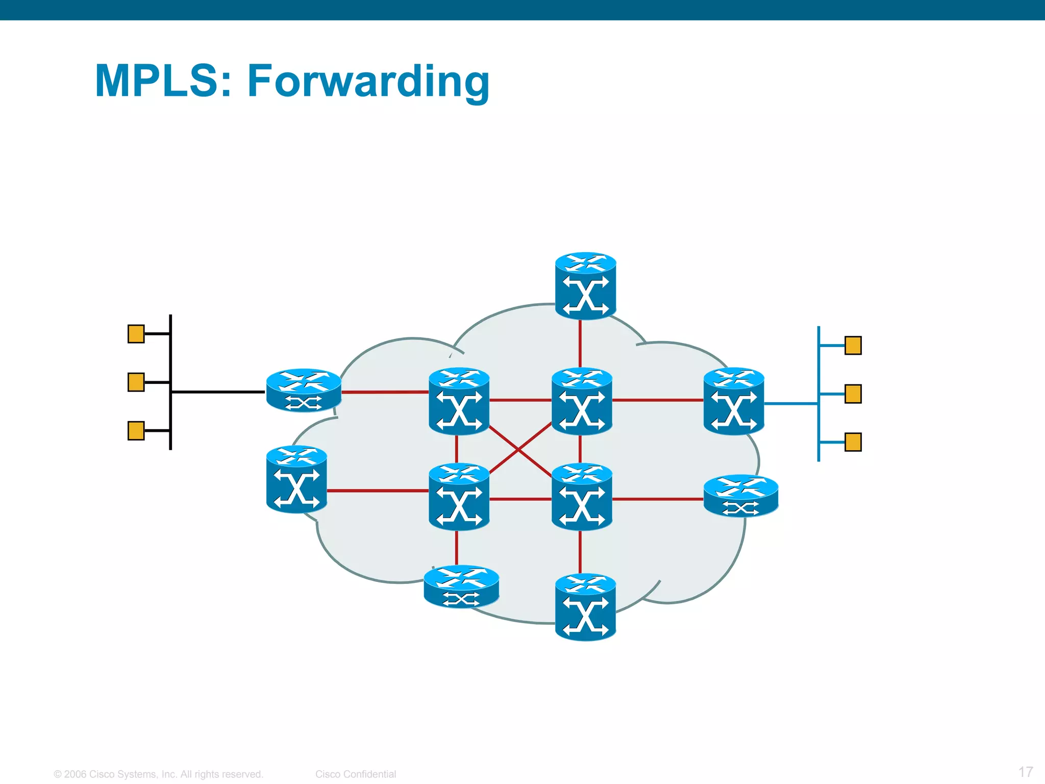
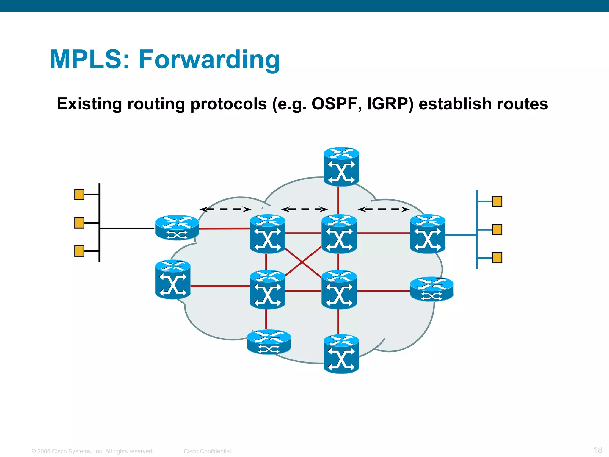
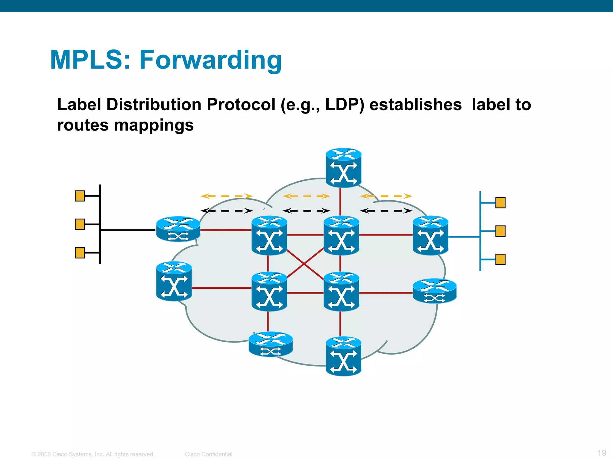
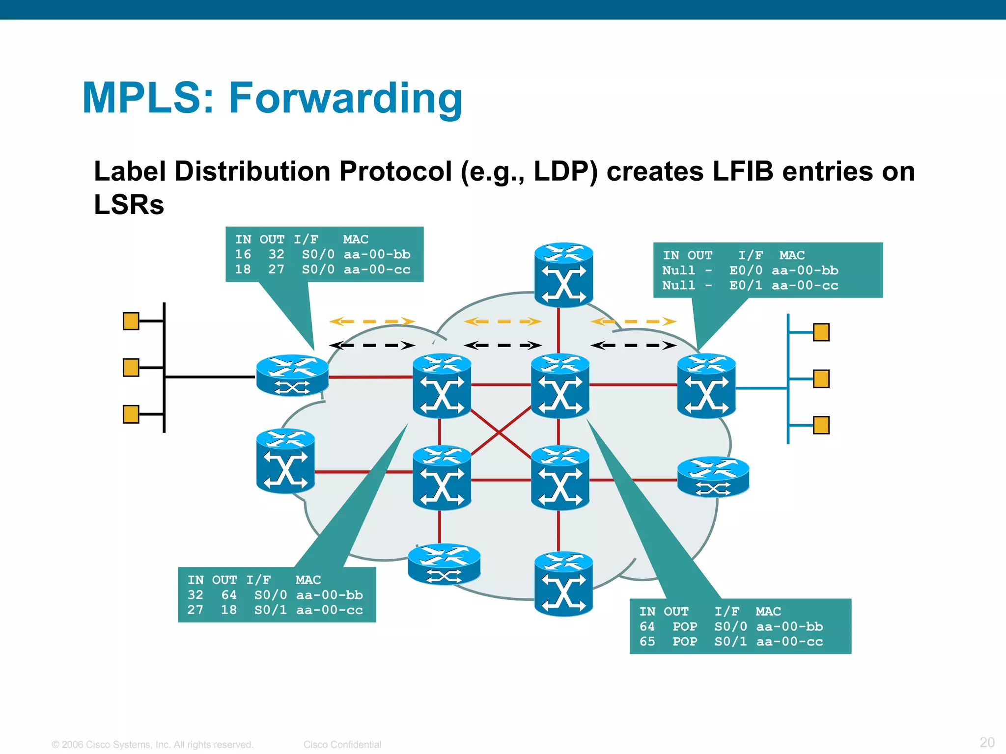
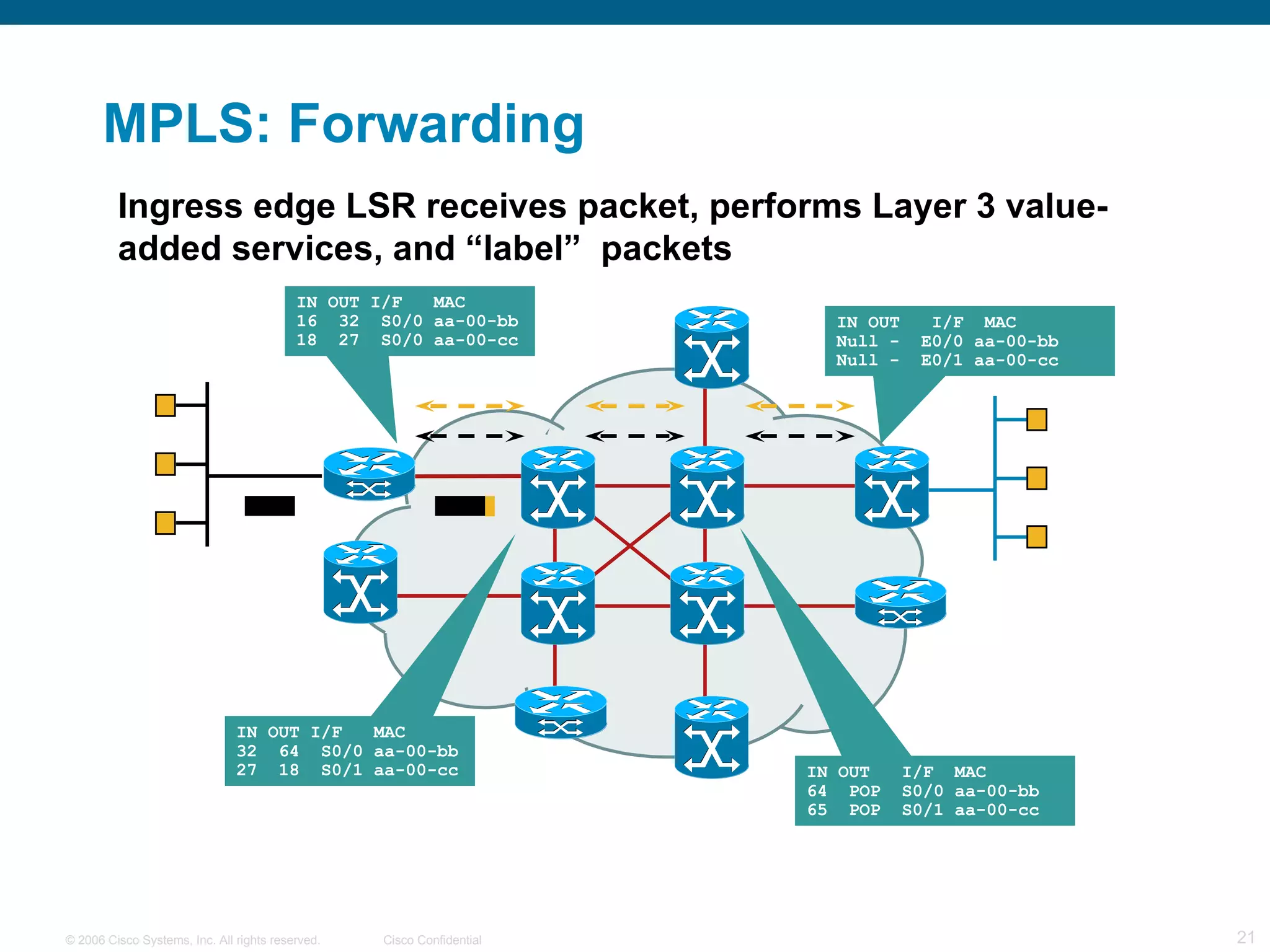
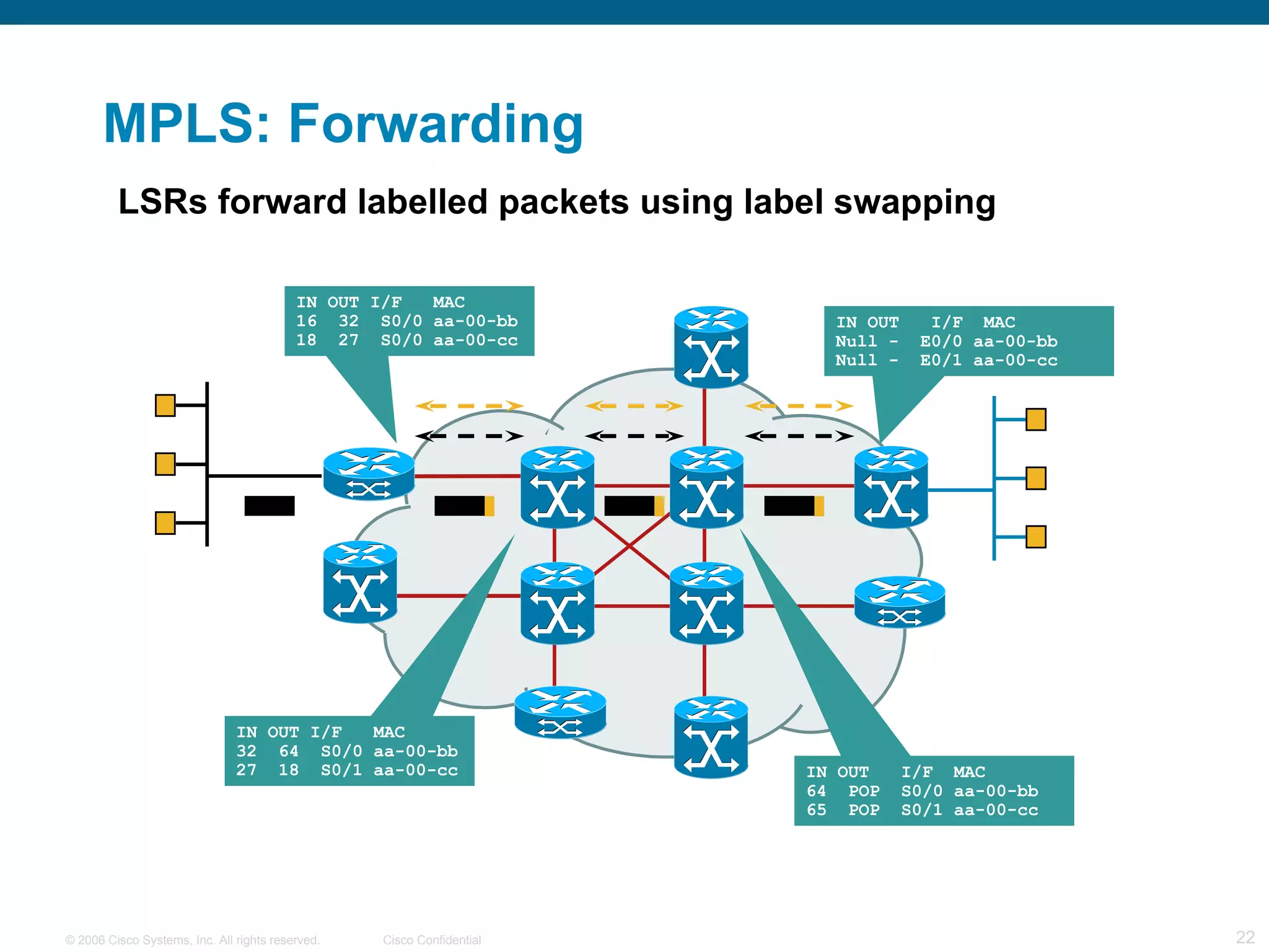
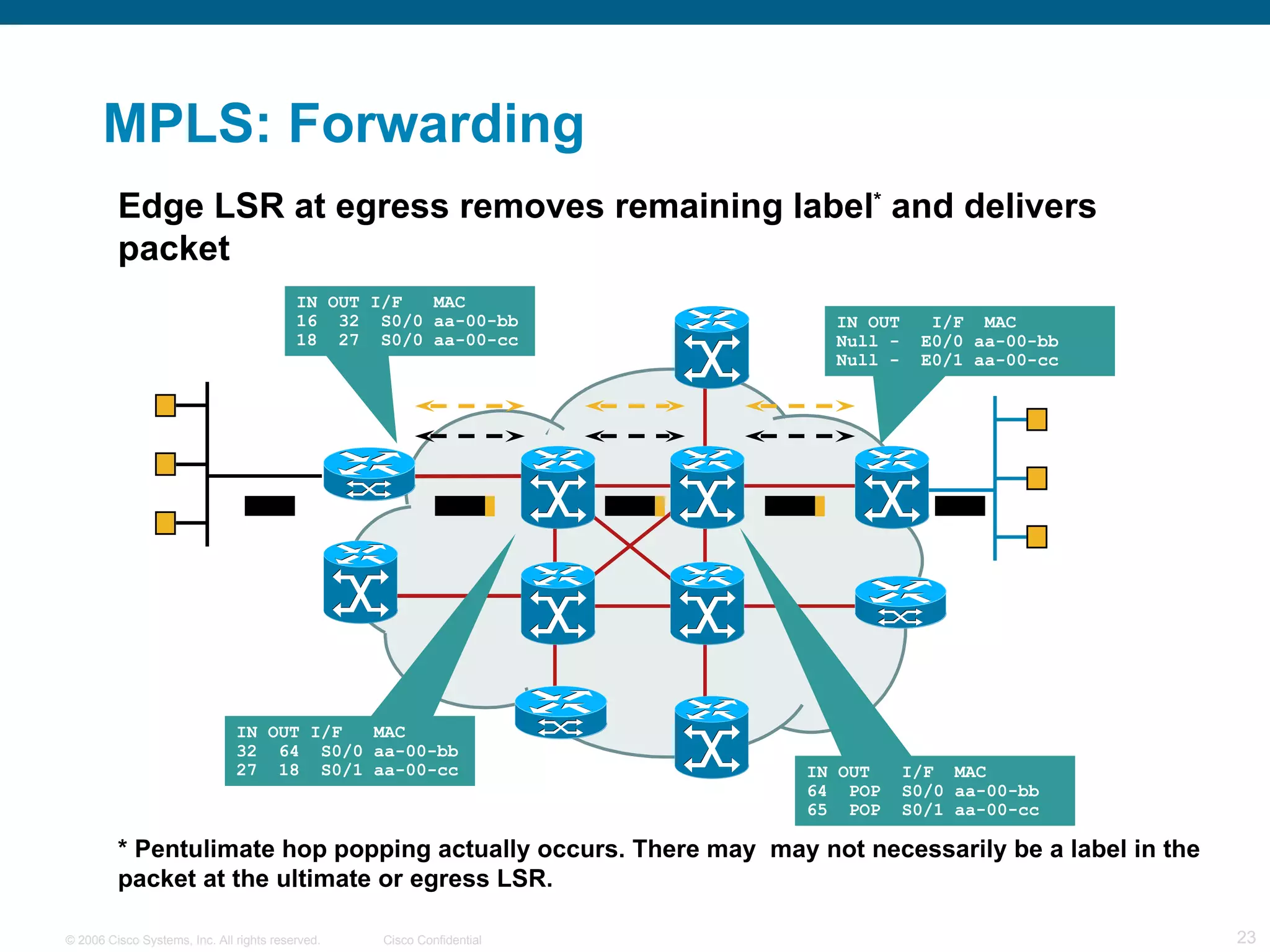
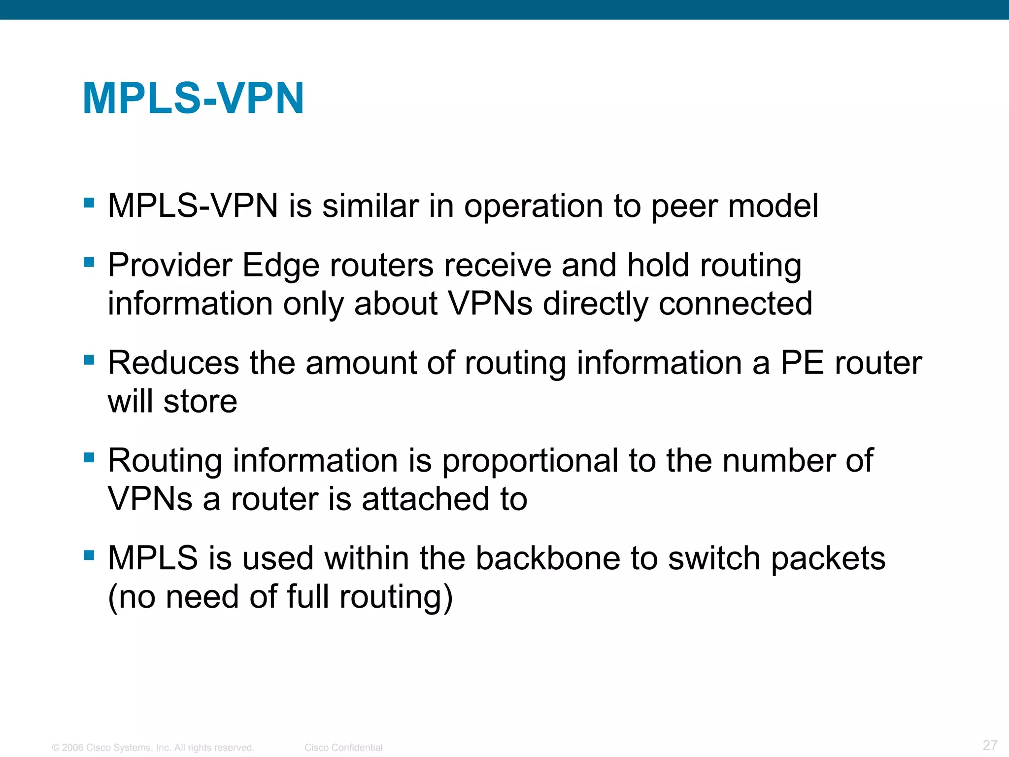
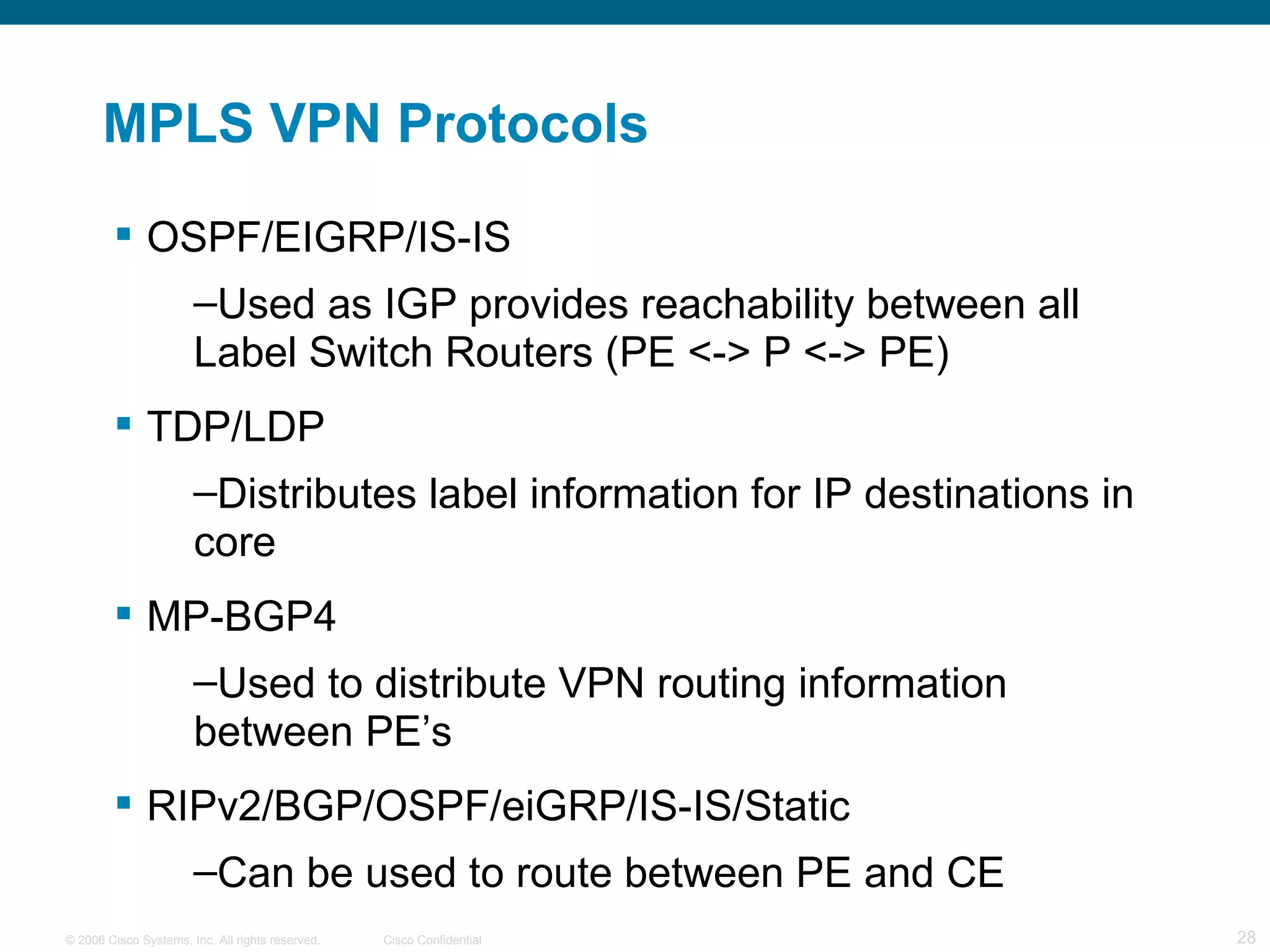
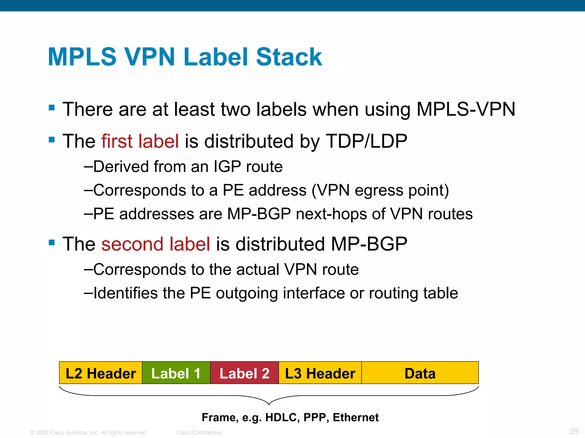
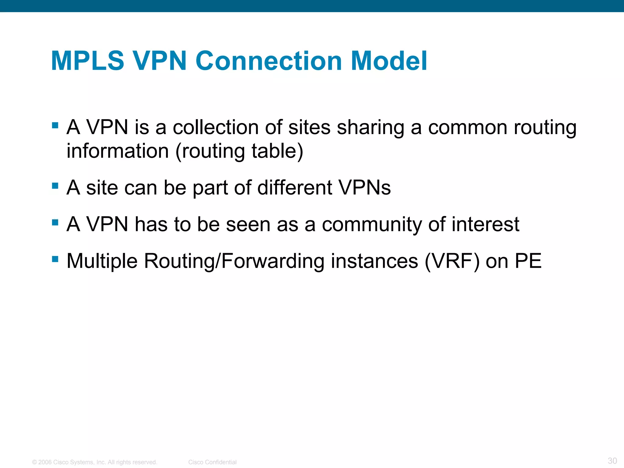
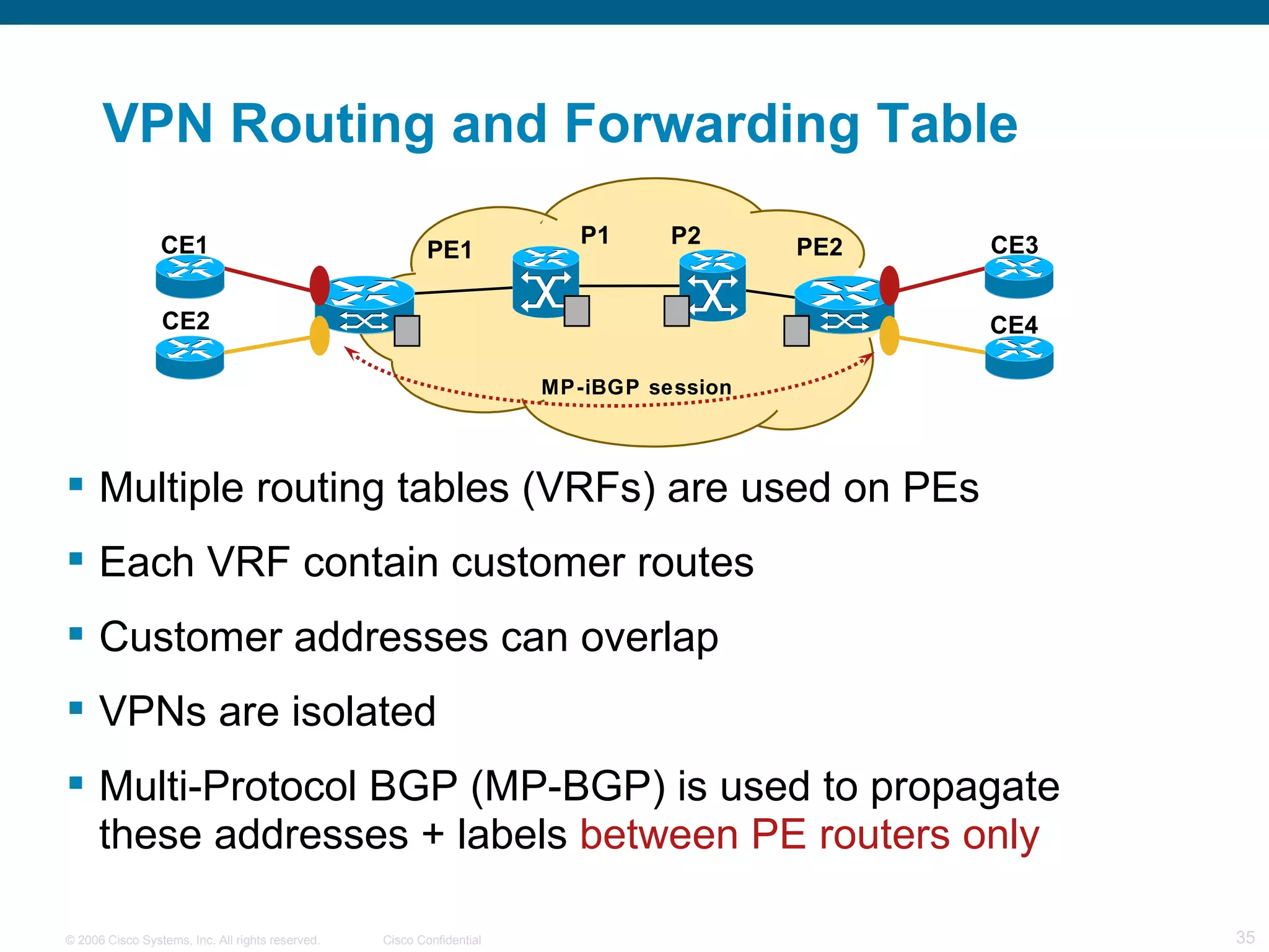
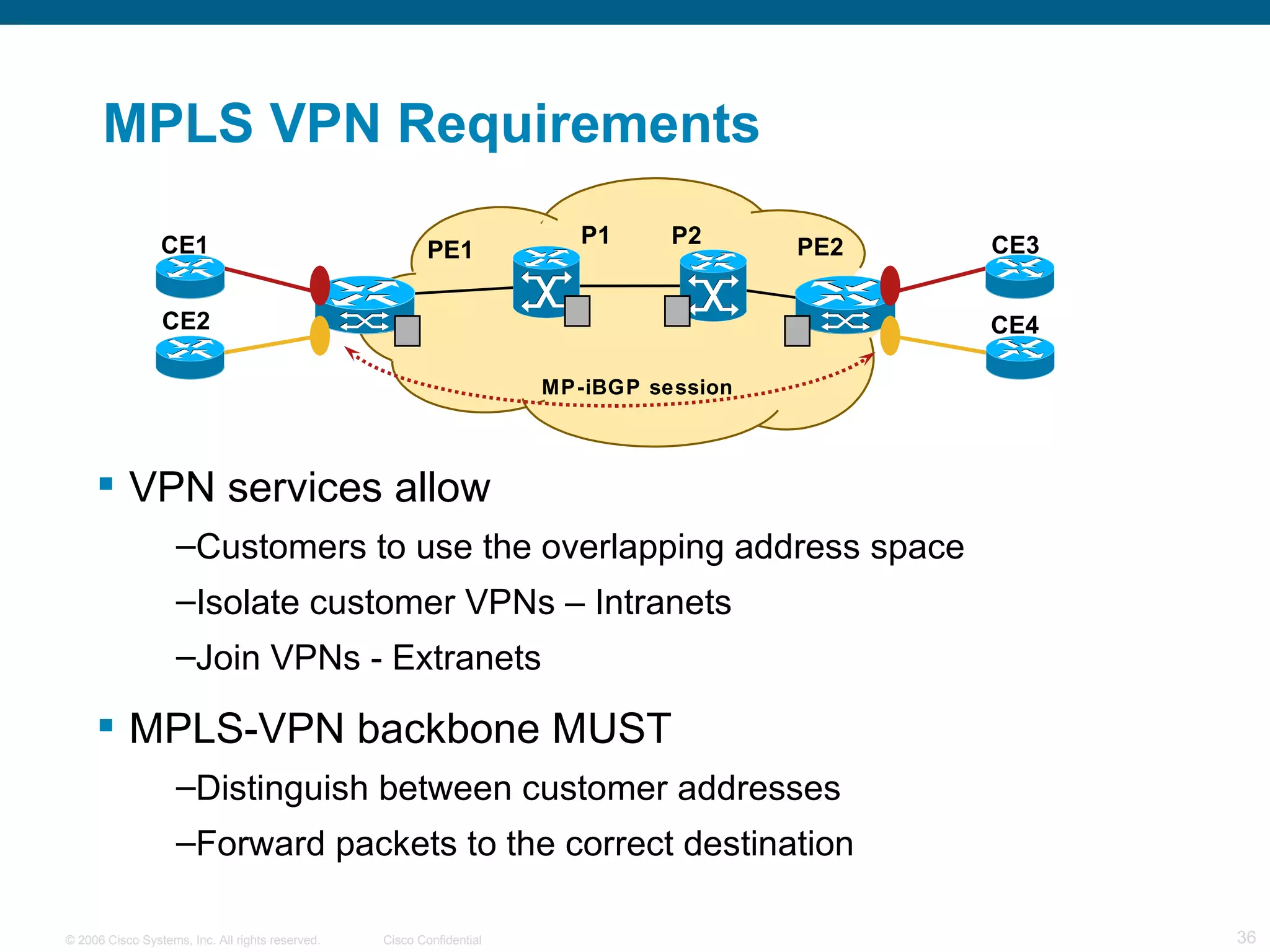
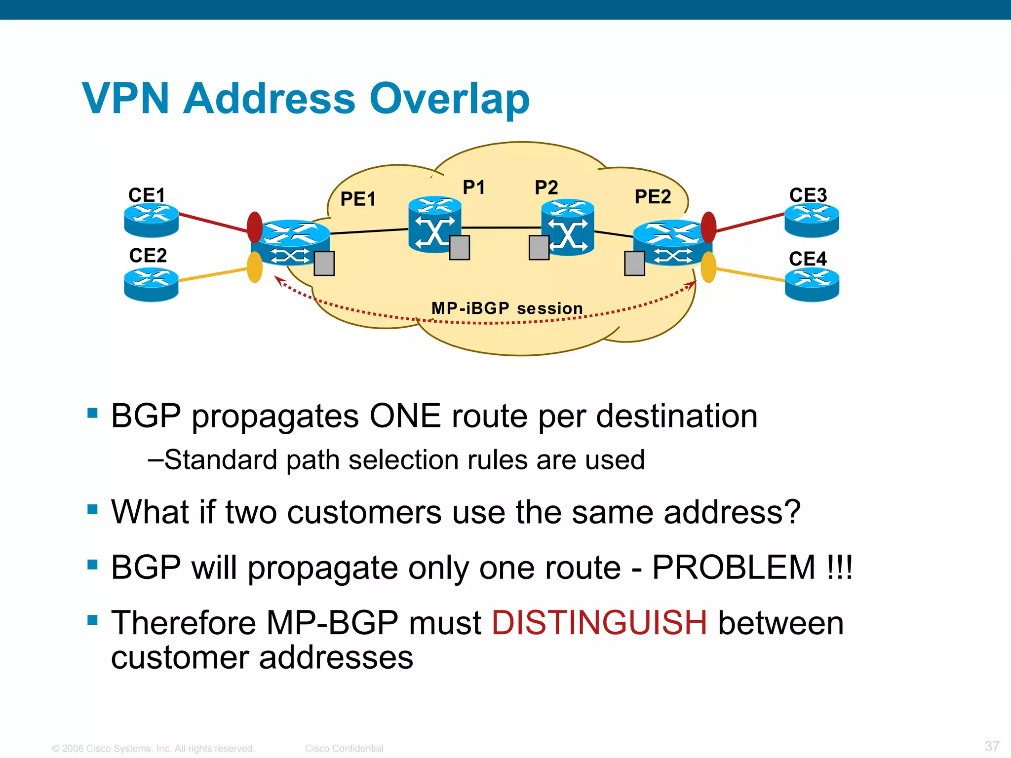
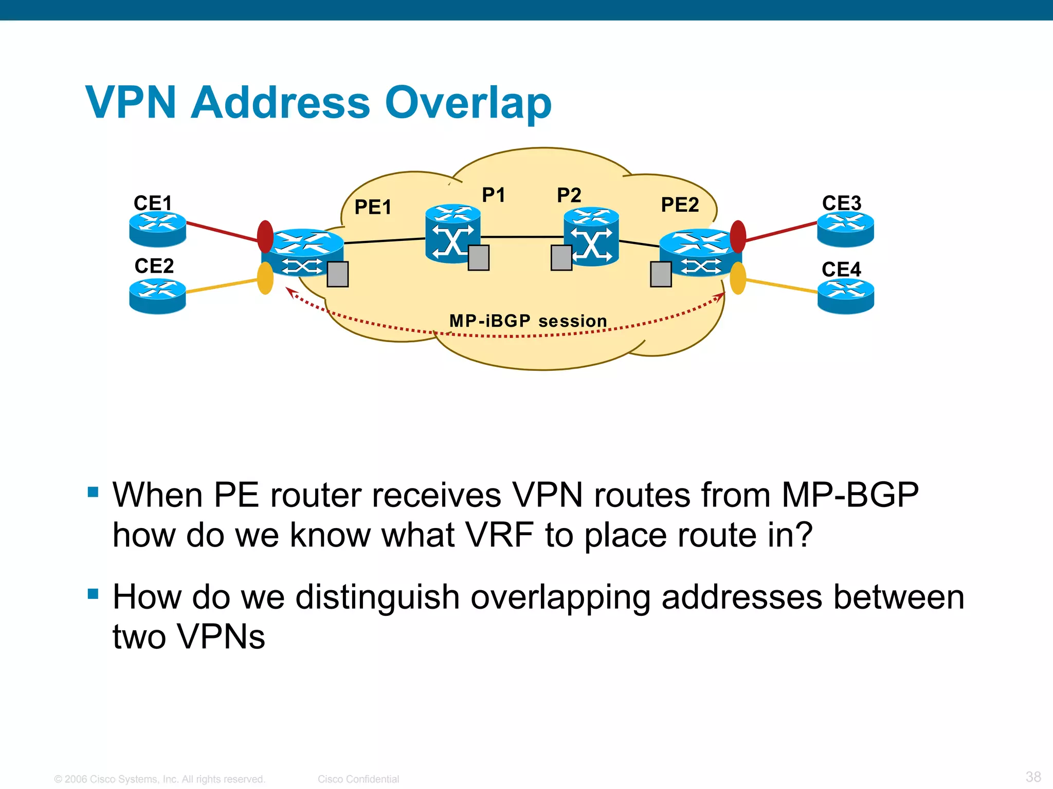
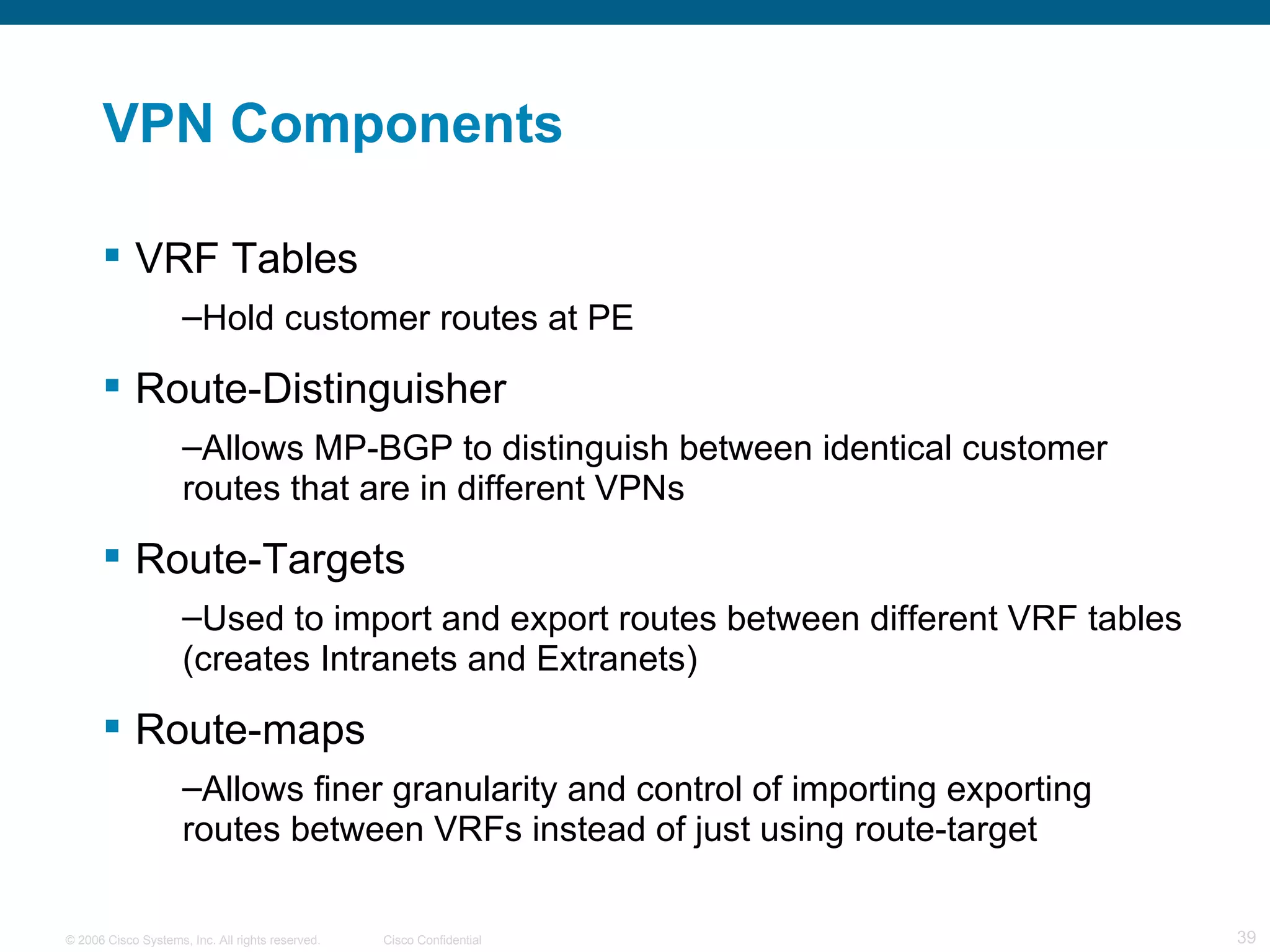
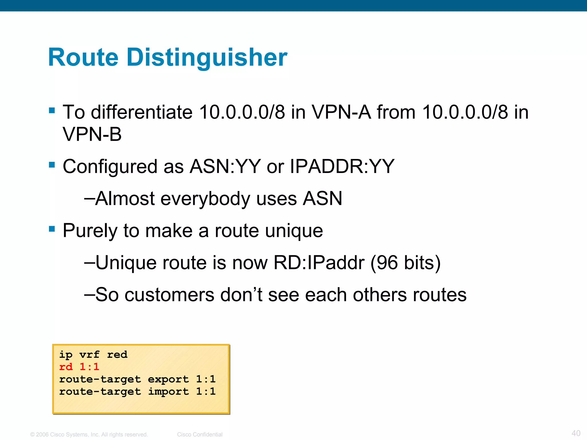
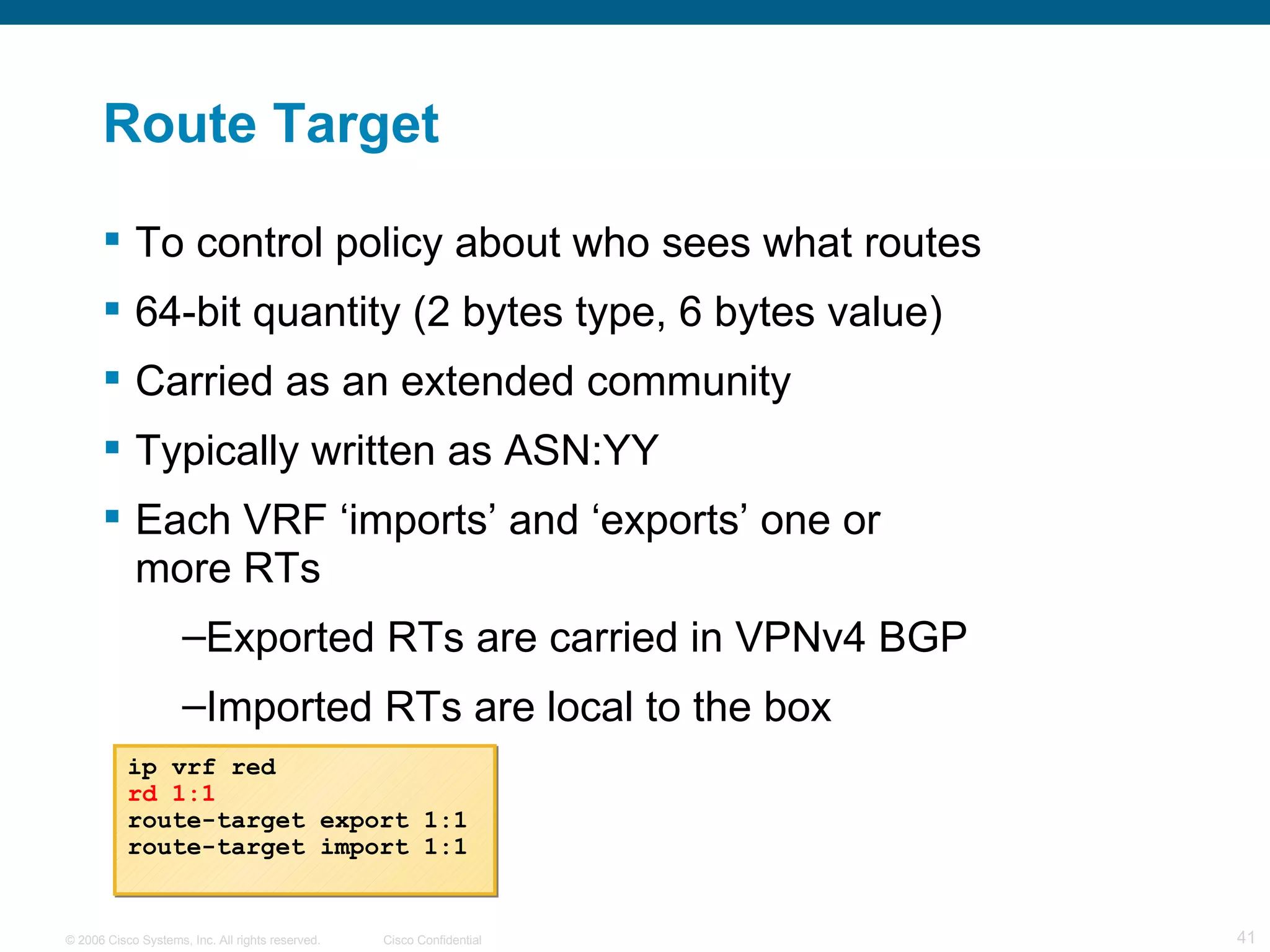
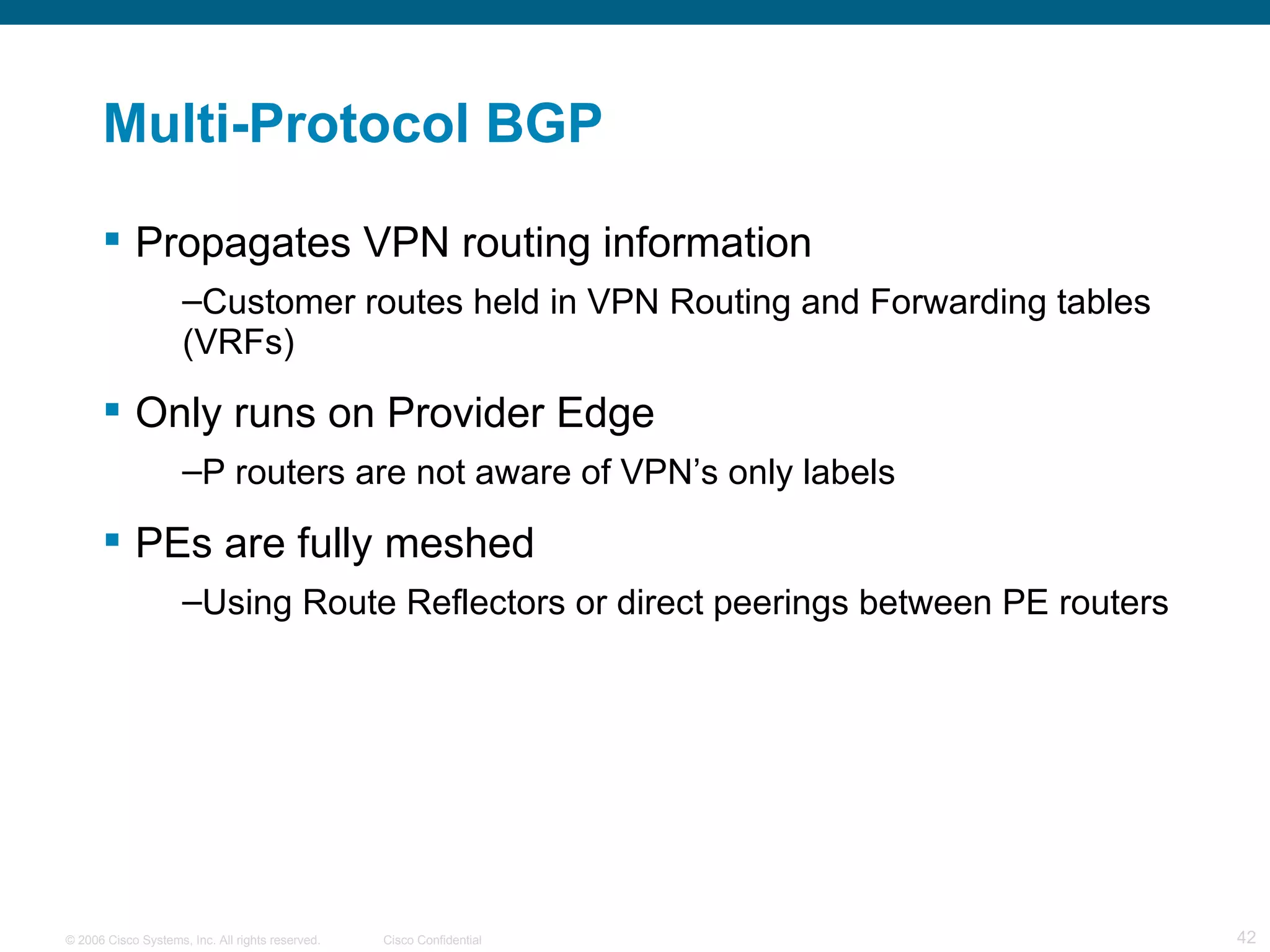
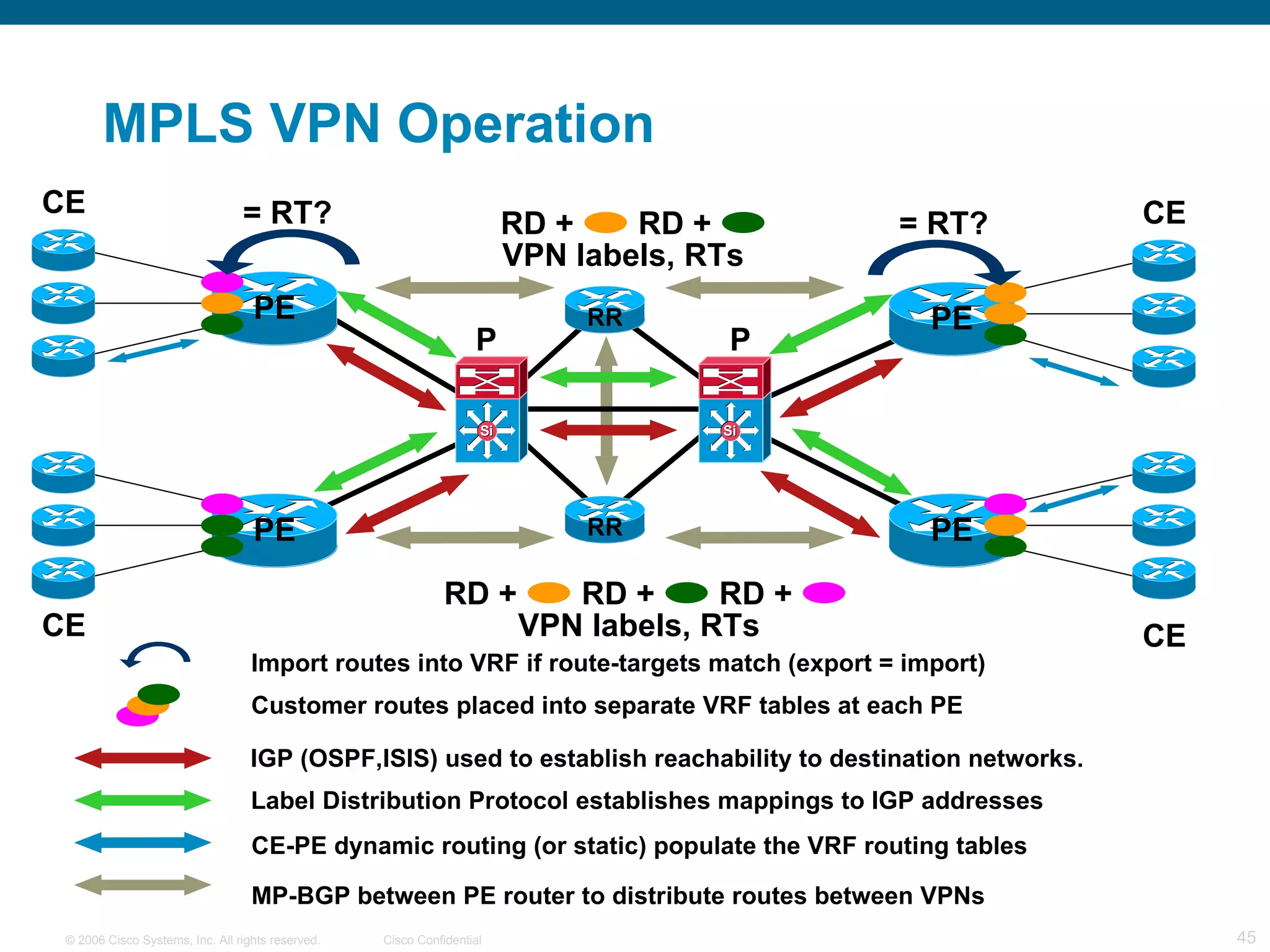
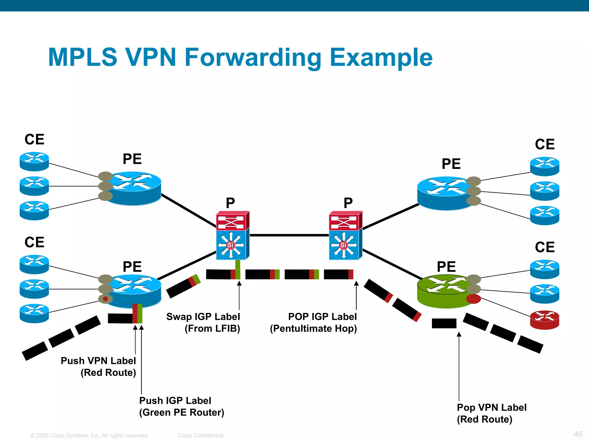
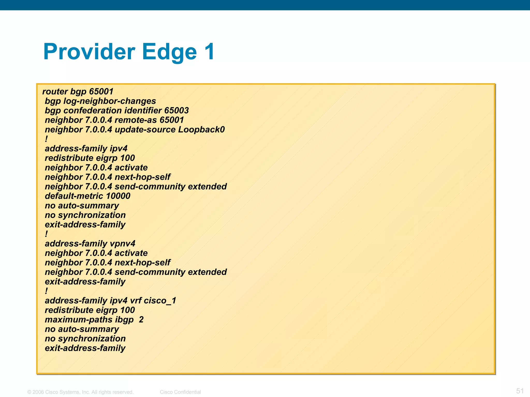
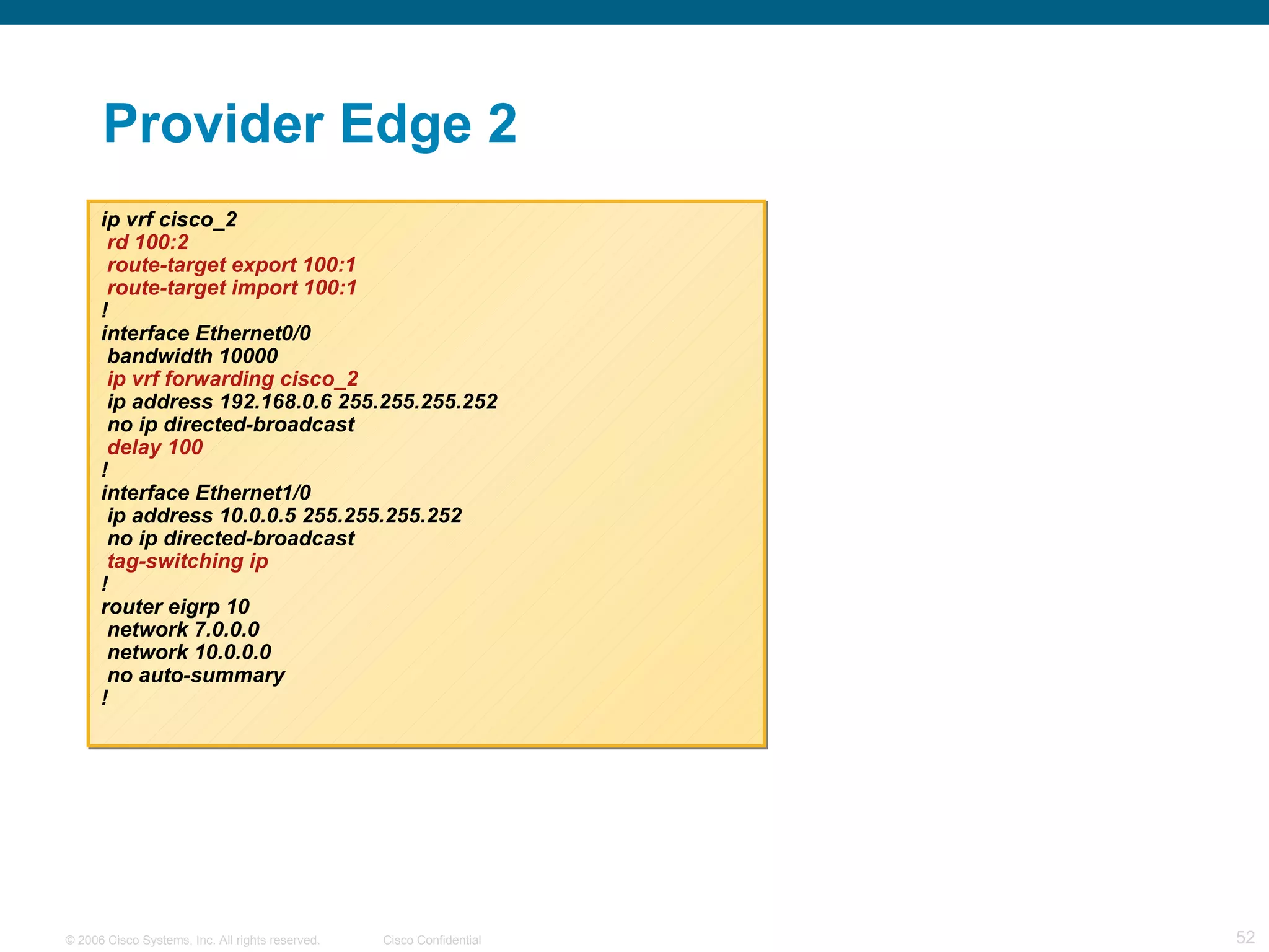
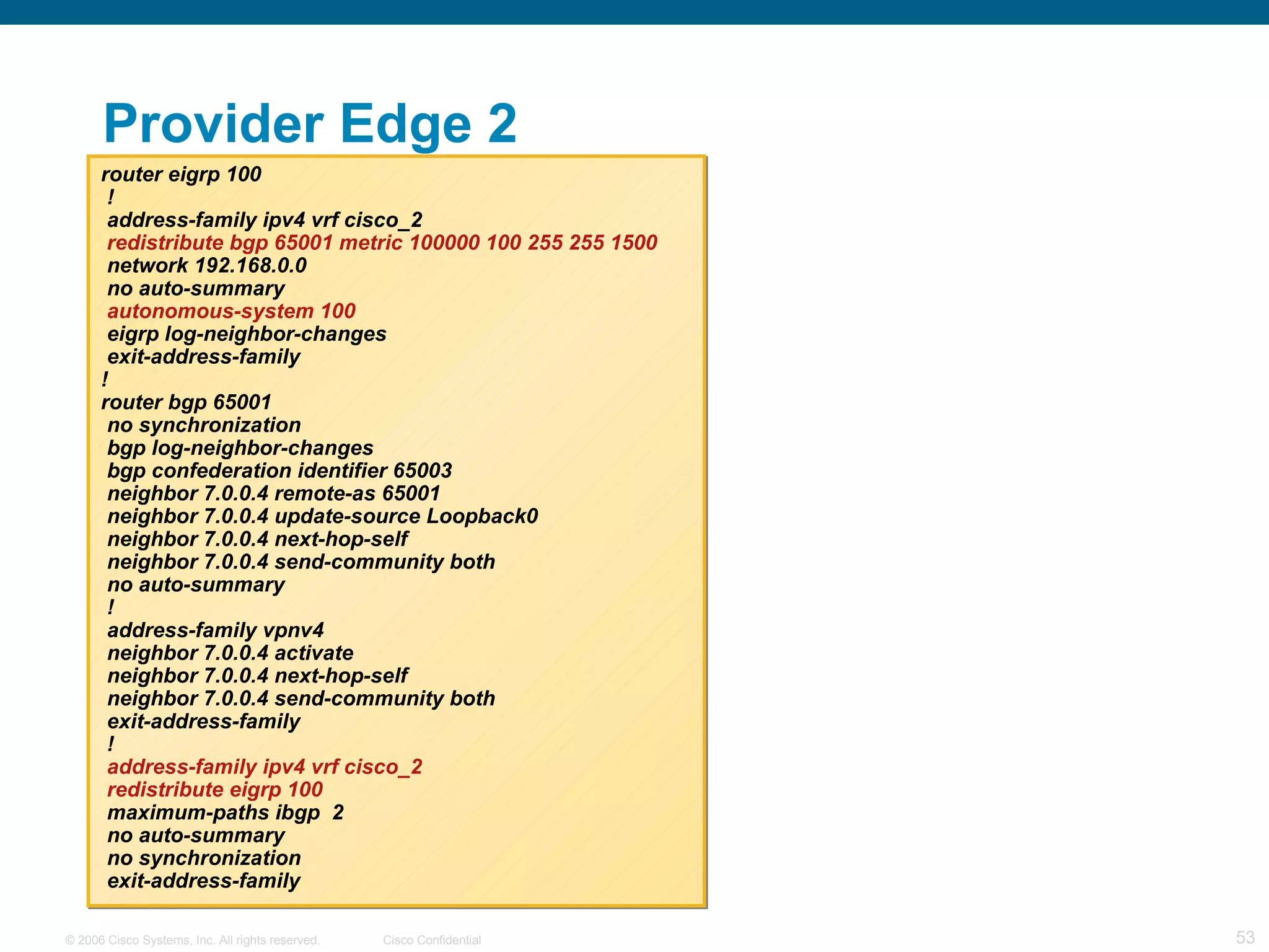
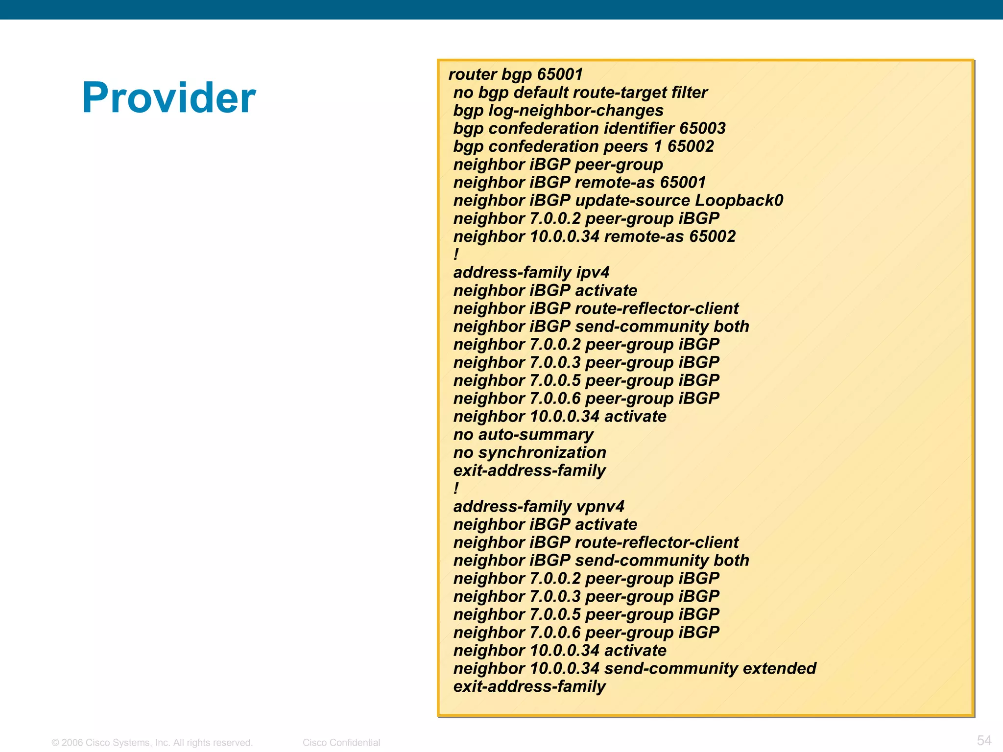
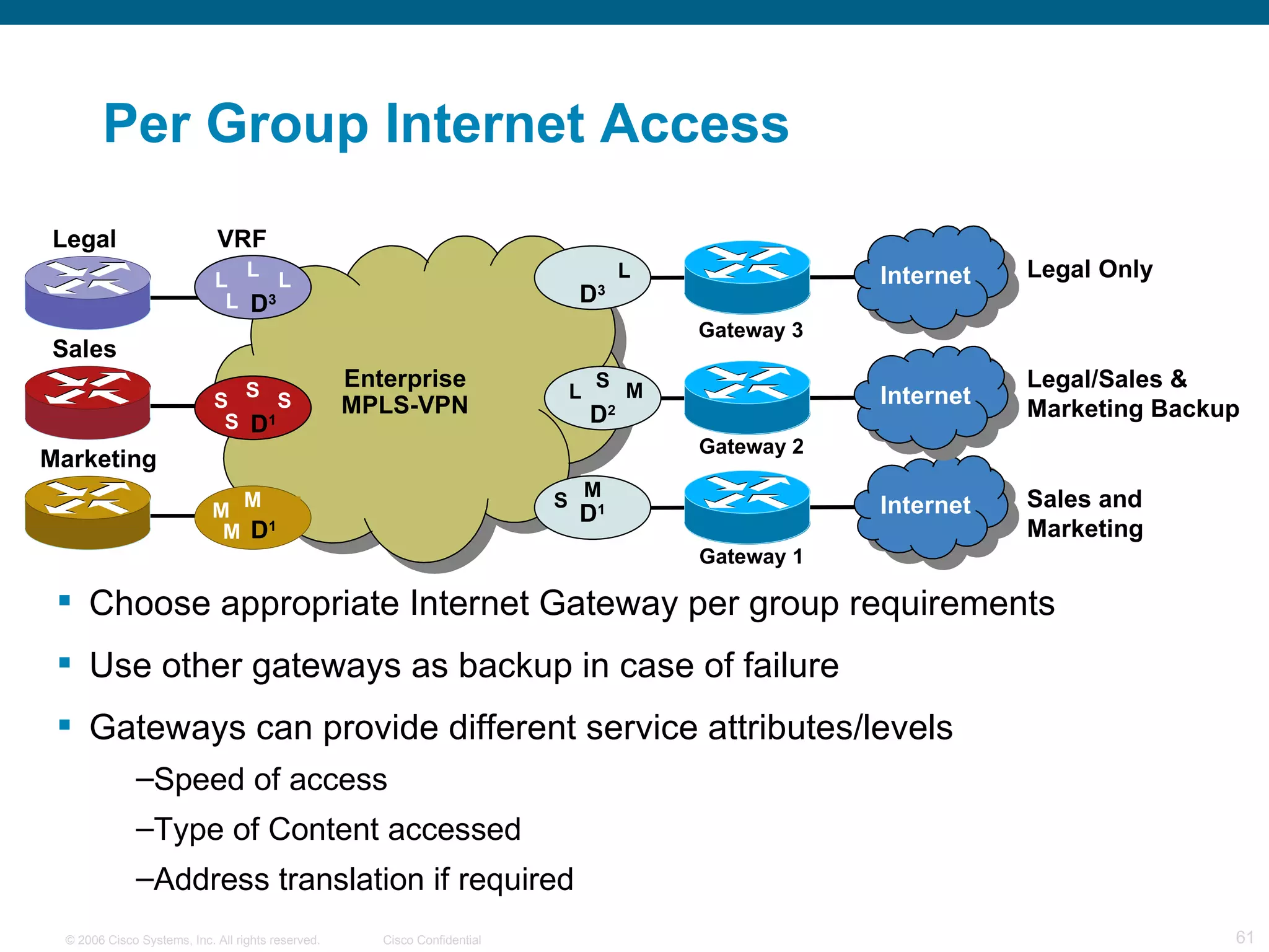
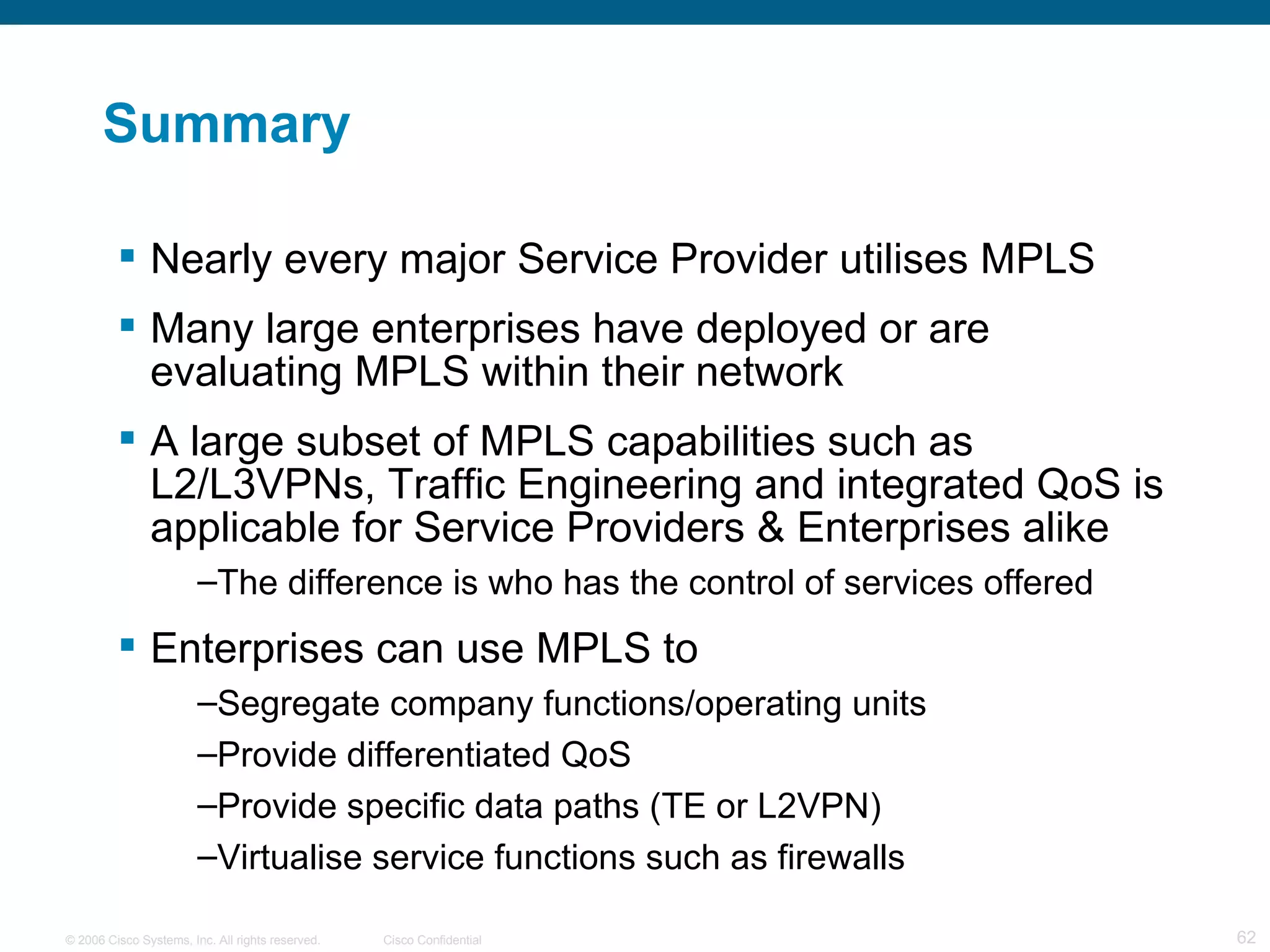
MPLS Services Kristof De Brouwer
Agenda MPLS Concepts  MPLS Components MPLS VPN MPLS Service Provider Example Enterprise MPLS Summary
MPLS “ MPLS is like having Paris Hilton as your girlfriend. The concept is fantastic, but in reality the experience might not be what you expected. But… we’re still willing to give it a go as long as we can understand/handle her behaviour”
MPLS Concepts © 2003 Cisco Systems, Inc. All rights reserved. MPLS  Concepts
MPLS concepts MPLS: Multi Protocol Label Switching Packet forwarding is done based on labels Labels assigned when the packet enters the network Labels inserted between layer 2 and layer 3 headers Separates ROUTING from FORWARDING Routing uses IP addresses Forwarding uses Labels
IP Routing 171.69 Packets Forwarded Based on IP Address Data Address  Prefix 128.89 171.69 1 1 I/F … Address  Prefix 128.89 171.69 0 1 … 0 1 I/F 128.89 0 1 128.89.25.4 Data Address  Prefix 128.89 0 … … I/F Data Data 128.89.25.4 128.89.25.4 128.89.25.4 Route Update
Operation Traditional routing Each router holds entire routing table and forwards to next hop (destination based routing) Routes on L3 Destination address MPLS combines L3 routing with label swapping and forwarding MPLS Forwarding Label imposed at ingress router.  All forwarding decisions then made on label only  Tag stripped at egress
Label Header  Label 1 2 3 4 5 6 7 8 EXP S TTL Bit 2 3 4 1 Byte Label EXP S TTL Label Value (20 bits) Class of Service (3 bits) Bottom of Stack (1 bit) Time to Live
Label Encapsulation PPP Ethernet Frame Relay Label IP header Label Label IP Header IP Header Data ATM Header Label Data ATM Header Packet over SONET/SDH Ethernet Frame Relay PVC ATM  PVC’s Subsequent   cells Data Data Data IP Header FRAME
Label Stacking Arrange labels in a stack Inner labels can be used to designate services VPN Label Outer label used to route/switch the MPLS packets in the network - IGP Label Allows building services such as:  MPLS VPNs Traffic engineering and fast re-route VPNs over traffic engineered core Any transport over MPLS Inner Label Outer Label IP Header TE Label IGP Label VPN Label
MPLS  Components © 2003 Cisco Systems, Inc. All rights reserved.
MPLS Components Edge Label Switching Routers (ELSR or PE) Label previously unlabeled packets - at the beginning of a Label Switched Path (LSP) Strip labels from labeled packets - at the end of an LSP Label Switching Routers (LSR or P)  Forward labeled packets based on the information carried by labels
MPLS Components LSR LSR LSR LSR ELSR ELSR P Network (Provider Control) PE CE CE PE ELSR ELSR C Network (Customer Control) C Network (Customer Control) P
Label Distribution Protocol (LDP) Defined in RFC 3036 and 3037 Used to distribute labels in a MPLS network Forwarding Equivalence Class (FEC) How packets are mapped to LSPs  Advertise labels per FEC  Reach destination a.b.c.d with label x  Neighbor discovery UDP and TCP Ports UDP port for LDP Hello messages = 646 TCP port for establishing LDP session connections = 646
TDP and LDP Tag Distribution Protocol Pre-cursor to LDP Used for Cisco tag switching TDP and LDP supported on the same box Per neighbor/link basis  Per target basis
Control and Forward Plane Separation MPLS Process Route Updates/ Adjacency Label Bind Updates/ Adjacency IP Traffic MPLS Traffic Control Plane Data Plane LFIB Routing Process RIB LIB FIB
MPLS: Forwarding
MPLS: Forwarding Existing routing protocols (e.g. OSPF, IGRP) establish routes
MPLS: Forwarding Label Distribution Protocol (e.g., LDP) establishes  label to routes mappings
MPLS: Forwarding Label Distribution Protocol (e.g., LDP) creates LFIB entries on LSRs IN OUT  I/F  MAC Null -  E0/0 aa-00-bb Null -  E0/1 aa-00-cc  IN OUT I/F  MAC 16  32  S0/0 aa-00-bb 18  27  S0/0 aa-00-cc  IN OUT I/F  MAC 32  64  S0/0 aa-00-bb 27  18  S0/1 aa-00-cc  IN OUT  I/F  MAC 64  POP  S0/0 aa-00-bb 65  POP  S0/1 aa-00-cc
MPLS: Forwarding Ingress edge LSR receives packet, performs Layer 3 value-added services, and “label”  packets IN OUT  I/F  MAC Null -  E0/0 aa-00-bb Null -  E0/1 aa-00-cc  IN OUT I/F  MAC 16  32  S0/0 aa-00-bb 18  27  S0/0 aa-00-cc  IN OUT I/F  MAC 32  64  S0/0 aa-00-bb 27  18  S0/1 aa-00-cc  IN OUT  I/F  MAC 64  POP  S0/0 aa-00-bb 65  POP  S0/1 aa-00-cc
MPLS: Forwarding LSRs forward labelled packets using label swapping IN OUT  I/F  MAC Null -  E0/0 aa-00-bb Null -  E0/1 aa-00-cc  IN OUT I/F  MAC 16  32  S0/0 aa-00-bb 18  27  S0/0 aa-00-cc  IN OUT I/F  MAC 32  64  S0/0 aa-00-bb 27  18  S0/1 aa-00-cc  IN OUT  I/F  MAC 64  POP  S0/0 aa-00-bb 65  POP  S0/1 aa-00-cc
MPLS: Forwarding Edge LSR at egress removes remaining label *  and delivers packet * Pentulimate hop popping actually occurs. There may  may not necessarily be a label in the packet at the ultimate or egress LSR.  IN OUT  I/F  MAC Null -  E0/0 aa-00-bb Null -  E0/1 aa-00-cc  IN OUT I/F  MAC 16  32  S0/0 aa-00-bb 18  27  S0/0 aa-00-cc  IN OUT I/F  MAC 32  64  S0/0 aa-00-bb 27  18  S0/1 aa-00-cc  IN OUT  I/F  MAC 64  POP  S0/0 aa-00-bb 65  POP  S0/1 aa-00-cc
MPLS MPLS  VPN
Virtual Networks Virtual Private Networks Virtual Dialup Networks Virtual LANs Overlay VPN Peer-to-Peer VPN Layer-2 VPN Layer-3 VPN Access lists (Shared router) Split routing (Dedicated router) MPLS/VPN X.25 F/R ATM GRE IPSec Virtual Network Models
What is an MPLS-VPN? An IP network  infrastructure delivering private network services over a public infrastructure Use a layer 3 backbone Scalability, easy provisioning Global as well as non-unique private address space QoS Controlled access Easy configuration for customers
MPLS-VPN MPLS-VPN is similar in operation to peer model Provider Edge routers receive and hold routing information only about VPNs directly connected Reduces the amount of routing information a PE router will store Routing information is proportional to the number of VPNs a router is attached to MPLS is used within the backbone to switch packets (no need of full routing)
MPLS VPN Protocols OSPF/EIGRP/IS-IS Used as IGP provides reachability between all Label Switch Routers (PE <-> P <-> PE) TDP/LDP  Distributes label information for IP destinations in core MP-BGP4 Used to distribute VPN routing information between PE’s RIPv2/BGP/OSPF/eiGRP/IS-IS/Static Can be used to route between PE and CE
MPLS VPN Label Stack There are at least two labels when using MPLS-VPN The  first label  is distributed by TDP/LDP Derived from an IGP route Corresponds to a PE address (VPN egress point) PE addresses are MP-BGP next-hops of VPN routes The  second label  is distributed MP-BGP Corresponds to the actual VPN route Identifies the PE outgoing interface or routing table Label 2 L3 Header Data Label 1 L2 Header Frame, e.g. HDLC, PPP, Ethernet
MPLS VPN Connection Model A VPN is a collection of sites sharing a common routing information (routing table) A site can be part of different VPNs A VPN has to be seen as a community of interest  Multiple Routing/Forwarding instances (VRF) on PE
MPLS VPN Connection Model A site belonging to different VPNs may or MAY NOT be used as a transit point between VPNs If two or more VPNs have a common site, address space must be unique among these VPNs VPN-A VPN-C VPN-B Site-1 Site-3 Site-4 Site-2
Routing Tables PE routers maintain separate routing tables Global Routing Table All the PE and P routes populated by the VPN backbone IGP (ISIS or OSPF)  VPN Routing and Forwarding Tables (VRF) Routing and Forwarding table associated with one or more directly connected sites (CEs) VRF are associated to (sub/virtual/tunnel) interfaces Interfaces may share the same VRF if the connected sites may share the same routing information PE CE2 CE1 PE-CE routing VPN Backbone IGP (OSPF, ISIS) VRF Global Routing Table
VRF Table A VRF is the routing and forwarding instance for a set of sites with identical connectivity requirements. Data structures associated with a VRF: IP routing table Cisco Express Forwarding (CEF) forwarding table  Set of rules and routing protocol parameters (contexts) List of interfaces that use the VRF Other information associated with a VRF: Route Distinguisher (RD) Set of import and export route targets
IGP and label distribution in the backbone All routers (P and PE) run an IGP and label distribution protocol Each P and PE router has routes for the backbone nodes and a label is associated to each route MPLS forwarding is used within the core PE1 PE2 P1 P2 LFIB for PE-1 LFIB for P1 LFIB for P2 LFIB for PE2 CE2 CE1 CE4 CE3 19 18 17 IN OUT Next Hop Dest POP S0/0 P1 65 P1 P2 50 P1 PE2 67 65 50 IN OUT Next Hop Dest POP S3/0 PE1 POP E0/2 P2 34 P2 PE2 39 38 34 IN OUT Next Hop Dest 67 P1 PE1 POP E0/1 P1 POP P1 PE2 18 36 44 IN OUT Next Hop Dest 39 P2 PE1 65 P2 P2 38 P2 P1
VPN Routing and Forwarding Table Multiple routing tables (VRFs) are used on PEs Each VRF contain customer routes Customer addresses can overlap VPNs are isolated Multi-Protocol BGP (MP-BGP) is used to propagate these addresses + labels  between PE routers only PE1 PE2 P1 P2 MP-iBGP session CE2 CE1 CE4 CE3
MPLS VPN Requirements VPN services allow  Customers to use the overlapping address space Isolate customer VPNs – Intranets Join VPNs - Extranets MPLS-VPN backbone MUST Distinguish between customer addresses Forward packets to the correct destination PE1 PE2 P1 P2 MP-iBGP session CE2 CE1 CE4 CE3
VPN Address Overlap BGP propagates ONE route per destination Standard path selection rules are used What if two customers use the same address? BGP will propagate only one route - PROBLEM !!! Therefore MP-BGP must  DISTINGUISH  between customer addresses PE1 PE2 P1 P2 MP-iBGP session CE2 CE1 CE4 CE3
VPN Address Overlap When PE router receives VPN routes from MP-BGP how do we know what VRF to place route in?  How do we distinguish overlapping addresses between two VPNs PE1 PE2 P1 P2 MP-iBGP session CE2 CE1 CE4 CE3
VPN Components VRF Tables Hold customer routes at PE  Route-Distinguisher Allows MP-BGP to distinguish between identical customer routes that are in different VPNs  Route-Targets Used to import and export routes between different VRF tables (creates Intranets and Extranets) Route-maps Allows finer granularity and control of importing exporting routes between VRFs instead of just using route-target
Route Distinguisher To differentiate 10.0.0.0/8 in VPN-A from 10.0.0.0/8 in VPN-B Configured as ASN:YY or IPADDR:YY Almost everybody uses ASN Purely to make a route unique Unique route is now RD:IPaddr (96 bits)  So customers don’t see each others routes ip vrf red rd 1:1 route-target export 1:1 route-target import 1:1
Route Target To control policy about who sees what routes 64-bit quantity (2 bytes type, 6 bytes value) Carried as an extended community Typically written as ASN:YY Each VRF ‘imports’ and ‘exports’ one or  more RTs Exported RTs are carried in VPNv4 BGP Imported RTs are local to the box ip vrf red rd 1:1 route-target export 1:1 route-target import 1:1
Multi-Protocol BGP Propagates VPN routing information Customer routes held in VPN Routing and Forwarding tables (VRFs) Only runs on Provider Edge P routers are not aware of VPN’s only labels PEs are fully meshed Using Route Reflectors or direct peerings between PE routers
Route-Target and Route-Distinguisher MP-BGP prepends an Route Distinguisher (RD) to each VPN route in order to make it unique MP-BGP assign a Route-Target (RT) to each VPN route to identify VPN it belongs to (or CUG) Route-Target is the colour of the route x x VPN-IPv4 update: RD1:X , Next-hop=PE1 RT=RED , Label=10 update X PE1 PE2 P1 P2 MP-iBGP session update X VPN-IPv4 update: RD2:X , Next-hop=PE1 RT=ORANGE , Label=12 update X update X VPN-IPv4 updates are translated into IPv4 address and inserted into the VRF corresponding to the RT value CE2 CE1 CE4 CE3
Route Propagation through MP-BGP When a PE router receives an MP-BGP VPN route: It checks the route-target value to VRF route-targets If match then route is inserted into appropriate VRF The label associated with the VPN route is stored and used to send packets towards the destination x x VPN-IPv4 update: RD1:X , Next-hop=PE1 RT=RED , Label=10 update X PE1 PE2 P1 P2 MP-iBGP session update X VPN-IPv4 update: RD2:X , Next-hop=PE1 RT=ORANGE , Label=12 update X update X VPN-IPv4 updates are translated into IPv4 address and inserted into the VRF corresponding to the RT value CE2 CE1 CE4 CE3
MPLS VPN Operation P P PE PE PE CE CE CE CE PE RR RR MP-BGP between PE router to distribute routes between VPNs IGP (OSPF,ISIS) used to establish reachability to destination networks. Label Distribution Protocol establishes mappings to IGP addresses  CE-PE dynamic routing (or static) populate the VRF routing tables Customer routes placed into separate VRF tables at each PE = RT? = RT? Import routes into VRF if route-targets match (export = import) RD + RD + RD + RD + RD + VPN labels, RTs VPN labels, RTs
MPLS VPN Forwarding Example PE P P PE CE CE PE PE CE CE Push VPN Label (Red Route) Push IGP Label (Green PE Router)  Swap IGP Label (From LFIB) POP IGP Label (Pentultimate Hop) Pop VPN Label (Red Route)
MPLS MPLS  Service Provider Example
 
Customer Edge interface Loopback0 ip address 7.0.0.1 255.255.255.255 no ip directed-broadcast interface Ethernet0/0 bandwidth 50000 ip address 192.168.0.1 255.255.255.252 no ip directed-broadcast delay 1 ! interface Ethernet1/0 bandwidth 10000 ip address 192.168.0.5 255.255.255.252 no ip directed-broadcast delay 100 ! ! router eigrp 100 network 7.0.0.0 network 192.168.0.0 eigrp stub connected no auto-summary
Provider Edge 1 ip vrf cisco_1 rd 100:1 route-target export 100:1 route-target import 100:1 ! interface Ethernet0/0 bandwidth 50000 ip vrf forwarding cisco_1 ip address 192.168.0.2 255.255.255.252 no ip directed-broadcast delay 1 ! router eigrp 10 network 7.0.0.0 network 10.0.0.0 no auto-summary ! router eigrp 100 ! address-family ipv4 vrf cisco_1 redistribute bgp 65001 metric 100000 100 255 255 1500 network 192.168.0.0 no auto-summary autonomous-system 100 eigrp log-neighbor-changes exit-address-family !
Provider Edge 1 router bgp 65001 bgp log-neighbor-changes bgp confederation identifier 65003 neighbor 7.0.0.4 remote-as 65001 neighbor 7.0.0.4 update-source Loopback0 ! address-family ipv4 redistribute eigrp 100 neighbor 7.0.0.4 activate neighbor 7.0.0.4 next-hop-self neighbor 7.0.0.4 send-community extended default-metric 10000 no auto-summary no synchronization exit-address-family ! address-family vpnv4 neighbor 7.0.0.4 activate neighbor 7.0.0.4 next-hop-self neighbor 7.0.0.4 send-community extended exit-address-family ! address-family ipv4 vrf cisco_1 redistribute eigrp 100 maximum-paths ibgp  2 no auto-summary no synchronization exit-address-family
Provider Edge 2 ip vrf cisco_2 rd 100:2 route-target export 100:1 route-target import 100:1 ! interface Ethernet0/0 bandwidth 10000 ip vrf forwarding cisco_2 ip address 192.168.0.6 255.255.255.252 no ip directed-broadcast delay 100 ! interface Ethernet1/0 ip address 10.0.0.5 255.255.255.252 no ip directed-broadcast tag-switching ip ! router eigrp 10 network 7.0.0.0 network 10.0.0.0 no auto-summary !
Provider Edge 2 router eigrp 100 ! address-family ipv4 vrf cisco_2 redistribute bgp 65001 metric 100000 100 255 255 1500 network 192.168.0.0 no auto-summary autonomous-system 100 eigrp log-neighbor-changes exit-address-family ! router bgp 65001 no synchronization bgp log-neighbor-changes bgp confederation identifier 65003 neighbor 7.0.0.4 remote-as 65001 neighbor 7.0.0.4 update-source Loopback0 neighbor 7.0.0.4 next-hop-self neighbor 7.0.0.4 send-community both no auto-summary ! address-family vpnv4 neighbor 7.0.0.4 activate neighbor 7.0.0.4 next-hop-self neighbor 7.0.0.4 send-community both exit-address-family ! address-family ipv4 vrf cisco_2 redistribute eigrp 100 maximum-paths ibgp  2 no auto-summary no synchronization exit-address-family
Provider  router bgp 65001 no bgp default route-target filter bgp log-neighbor-changes bgp confederation identifier 65003 bgp confederation peers 1 65002  neighbor iBGP peer-group neighbor iBGP remote-as 65001 neighbor iBGP update-source Loopback0 neighbor 7.0.0.2 peer-group iBGP neighbor 10.0.0.34 remote-as 65002 ! address-family ipv4 neighbor iBGP activate neighbor iBGP route-reflector-client neighbor iBGP send-community both neighbor 7.0.0.2 peer-group iBGP neighbor 7.0.0.3 peer-group iBGP neighbor 7.0.0.5 peer-group iBGP neighbor 7.0.0.6 peer-group iBGP neighbor 10.0.0.34 activate no auto-summary no synchronization exit-address-family ! address-family vpnv4 neighbor iBGP activate neighbor iBGP route-reflector-client neighbor iBGP send-community both neighbor 7.0.0.2 peer-group iBGP neighbor 7.0.0.3 peer-group iBGP neighbor 7.0.0.5 peer-group iBGP neighbor 7.0.0.6 peer-group iBGP neighbor 10.0.0.34 activate neighbor 10.0.0.34 send-community extended exit-address-family
MPLS  Enterprise
The Enterprise Perspective The benefit of MPLS/VPN is that “nothing special” is required of the CE router… Configure preferred IGP configured on CE/PE link  SP propagates those routes to other CE routers in the VPN  So the Enterprise can sit back and relax…  In reality, there are a few “finer details” to explore   PE-CE Routing Protocols Load Sharing Backdoor links Multi-homing
Enterprise MPLS Capabilities Segmentation User Groups Convergence Multiple Network Infrastructures Centralisation Minimise operational complexity Virtualisation Reduce capital resources
Closed User Group – Full Mesh Simple Intranet, CE can be a switch or a router  All locations/VLAN of user group fully peered Only Finance routes seen VLAN maps to VRF Enterprise MPLS-VPN VRF Finance Site 1 Finance Site 2 Finance Site 3 VLAN 205 F F F F F F F F F F F F F F F F F F
Common User Group – Partial Mesh Basic Extranet Routes can be imported directly into corresponding VRF No NAT necessary – Enterprise will have unique addressing Import granularity can be very fine Single host address can be imported as Extranet route Design Site A (DA) Design Site B (DB) Engineering Site B (EB) Engineering Site A (EA) VRF Enterprise MPLS-VPN D D D D D D D D D D EB EB EB EB EA EA EB EB DA DA DA E E E E E E E E E E DA DA DA
Branch to HQ – Hub and Spoke Forces all branches through the Central HQ Spokes cannot communicate directly  Appropriate security screening can be applied  Firewalls can be used with NAT to ensure correct return path Enterprise MPLS-VPN VRF Bank Branch 1 Bank Branch 2 VRF S1 S2 X S3 S2 X S3 X VRF Bank Branch 3 S1h S2h S3h S2h S1h S2h S3h S1h S3h Hub IN Spoke OUT Central HQ Optional Firewall NAT to  X BGP/OSPF/RIP routing BGP/OSPF/RIProuting S3 S3 S1 S2 S1 X
Per Group Internet Access Enterprise MPLS-VPN VRF Marketing Sales Legal Gateway 1  Gateway 2  Gateway 3   Internet Internet Internet Legal Only Legal/Sales & Marketing Backup Sales and Marketing Choose appropriate Internet Gateway per group requirements Use other gateways as backup in case of failure Gateways can provide different service attributes/levels Speed of access Type of Content accessed  Address translation if required M M M D 1 L D 3 L S M D 2 I I S M D 1 S S S S D 1 L L L L D 3
Summary Nearly every major Service Provider utilises MPLS Many large enterprises have deployed or are evaluating MPLS within their network A large subset of MPLS capabilities such as L2/L3VPNs, Traffic Engineering and integrated QoS is applicable for Service Providers & Enterprises alike The difference is who has the control of services offered Enterprises can use MPLS to Segregate company functions/operating units Provide differentiated QoS Provide specific data paths (TE or L2VPN) Virtualise service functions such as firewalls
Q & A
 

Mpls Services

  • 1.
  • 2.
    Agenda MPLS Concepts MPLS Components MPLS VPN MPLS Service Provider Example Enterprise MPLS Summary
  • 3.
    MPLS “ MPLSis like having Paris Hilton as your girlfriend. The concept is fantastic, but in reality the experience might not be what you expected. But… we’re still willing to give it a go as long as we can understand/handle her behaviour”
  • 4.
    MPLS Concepts ©2003 Cisco Systems, Inc. All rights reserved. MPLS Concepts
  • 5.
    MPLS concepts MPLS:Multi Protocol Label Switching Packet forwarding is done based on labels Labels assigned when the packet enters the network Labels inserted between layer 2 and layer 3 headers Separates ROUTING from FORWARDING Routing uses IP addresses Forwarding uses Labels
  • 6.
    IP Routing 171.69Packets Forwarded Based on IP Address Data Address Prefix 128.89 171.69 1 1 I/F … Address Prefix 128.89 171.69 0 1 … 0 1 I/F 128.89 0 1 128.89.25.4 Data Address Prefix 128.89 0 … … I/F Data Data 128.89.25.4 128.89.25.4 128.89.25.4 Route Update
  • 7.
    Operation Traditional routingEach router holds entire routing table and forwards to next hop (destination based routing) Routes on L3 Destination address MPLS combines L3 routing with label swapping and forwarding MPLS Forwarding Label imposed at ingress router. All forwarding decisions then made on label only Tag stripped at egress
  • 8.
    Label Header Label 1 2 3 4 5 6 7 8 EXP S TTL Bit 2 3 4 1 Byte Label EXP S TTL Label Value (20 bits) Class of Service (3 bits) Bottom of Stack (1 bit) Time to Live
  • 9.
    Label Encapsulation PPPEthernet Frame Relay Label IP header Label Label IP Header IP Header Data ATM Header Label Data ATM Header Packet over SONET/SDH Ethernet Frame Relay PVC ATM PVC’s Subsequent cells Data Data Data IP Header FRAME
  • 10.
    Label Stacking Arrangelabels in a stack Inner labels can be used to designate services VPN Label Outer label used to route/switch the MPLS packets in the network - IGP Label Allows building services such as: MPLS VPNs Traffic engineering and fast re-route VPNs over traffic engineered core Any transport over MPLS Inner Label Outer Label IP Header TE Label IGP Label VPN Label
  • 11.
    MPLS Components© 2003 Cisco Systems, Inc. All rights reserved.
  • 12.
    MPLS Components EdgeLabel Switching Routers (ELSR or PE) Label previously unlabeled packets - at the beginning of a Label Switched Path (LSP) Strip labels from labeled packets - at the end of an LSP Label Switching Routers (LSR or P) Forward labeled packets based on the information carried by labels
  • 13.
    MPLS Components LSRLSR LSR LSR ELSR ELSR P Network (Provider Control) PE CE CE PE ELSR ELSR C Network (Customer Control) C Network (Customer Control) P
  • 14.
    Label Distribution Protocol(LDP) Defined in RFC 3036 and 3037 Used to distribute labels in a MPLS network Forwarding Equivalence Class (FEC) How packets are mapped to LSPs Advertise labels per FEC Reach destination a.b.c.d with label x Neighbor discovery UDP and TCP Ports UDP port for LDP Hello messages = 646 TCP port for establishing LDP session connections = 646
  • 15.
    TDP and LDPTag Distribution Protocol Pre-cursor to LDP Used for Cisco tag switching TDP and LDP supported on the same box Per neighbor/link basis Per target basis
  • 16.
    Control and ForwardPlane Separation MPLS Process Route Updates/ Adjacency Label Bind Updates/ Adjacency IP Traffic MPLS Traffic Control Plane Data Plane LFIB Routing Process RIB LIB FIB
  • 17.
  • 18.
    MPLS: Forwarding Existingrouting protocols (e.g. OSPF, IGRP) establish routes
  • 19.
    MPLS: Forwarding LabelDistribution Protocol (e.g., LDP) establishes label to routes mappings
  • 20.
    MPLS: Forwarding LabelDistribution Protocol (e.g., LDP) creates LFIB entries on LSRs IN OUT I/F MAC Null - E0/0 aa-00-bb Null - E0/1 aa-00-cc IN OUT I/F MAC 16 32 S0/0 aa-00-bb 18 27 S0/0 aa-00-cc IN OUT I/F MAC 32 64 S0/0 aa-00-bb 27 18 S0/1 aa-00-cc IN OUT I/F MAC 64 POP S0/0 aa-00-bb 65 POP S0/1 aa-00-cc
  • 21.
    MPLS: Forwarding Ingressedge LSR receives packet, performs Layer 3 value-added services, and “label” packets IN OUT I/F MAC Null - E0/0 aa-00-bb Null - E0/1 aa-00-cc IN OUT I/F MAC 16 32 S0/0 aa-00-bb 18 27 S0/0 aa-00-cc IN OUT I/F MAC 32 64 S0/0 aa-00-bb 27 18 S0/1 aa-00-cc IN OUT I/F MAC 64 POP S0/0 aa-00-bb 65 POP S0/1 aa-00-cc
  • 22.
    MPLS: Forwarding LSRsforward labelled packets using label swapping IN OUT I/F MAC Null - E0/0 aa-00-bb Null - E0/1 aa-00-cc IN OUT I/F MAC 16 32 S0/0 aa-00-bb 18 27 S0/0 aa-00-cc IN OUT I/F MAC 32 64 S0/0 aa-00-bb 27 18 S0/1 aa-00-cc IN OUT I/F MAC 64 POP S0/0 aa-00-bb 65 POP S0/1 aa-00-cc
  • 23.
    MPLS: Forwarding EdgeLSR at egress removes remaining label * and delivers packet * Pentulimate hop popping actually occurs. There may may not necessarily be a label in the packet at the ultimate or egress LSR. IN OUT I/F MAC Null - E0/0 aa-00-bb Null - E0/1 aa-00-cc IN OUT I/F MAC 16 32 S0/0 aa-00-bb 18 27 S0/0 aa-00-cc IN OUT I/F MAC 32 64 S0/0 aa-00-bb 27 18 S0/1 aa-00-cc IN OUT I/F MAC 64 POP S0/0 aa-00-bb 65 POP S0/1 aa-00-cc
  • 24.
  • 25.
    Virtual Networks VirtualPrivate Networks Virtual Dialup Networks Virtual LANs Overlay VPN Peer-to-Peer VPN Layer-2 VPN Layer-3 VPN Access lists (Shared router) Split routing (Dedicated router) MPLS/VPN X.25 F/R ATM GRE IPSec Virtual Network Models
  • 26.
    What is anMPLS-VPN? An IP network infrastructure delivering private network services over a public infrastructure Use a layer 3 backbone Scalability, easy provisioning Global as well as non-unique private address space QoS Controlled access Easy configuration for customers
  • 27.
    MPLS-VPN MPLS-VPN issimilar in operation to peer model Provider Edge routers receive and hold routing information only about VPNs directly connected Reduces the amount of routing information a PE router will store Routing information is proportional to the number of VPNs a router is attached to MPLS is used within the backbone to switch packets (no need of full routing)
  • 28.
    MPLS VPN ProtocolsOSPF/EIGRP/IS-IS Used as IGP provides reachability between all Label Switch Routers (PE <-> P <-> PE) TDP/LDP Distributes label information for IP destinations in core MP-BGP4 Used to distribute VPN routing information between PE’s RIPv2/BGP/OSPF/eiGRP/IS-IS/Static Can be used to route between PE and CE
  • 29.
    MPLS VPN LabelStack There are at least two labels when using MPLS-VPN The first label is distributed by TDP/LDP Derived from an IGP route Corresponds to a PE address (VPN egress point) PE addresses are MP-BGP next-hops of VPN routes The second label is distributed MP-BGP Corresponds to the actual VPN route Identifies the PE outgoing interface or routing table Label 2 L3 Header Data Label 1 L2 Header Frame, e.g. HDLC, PPP, Ethernet
  • 30.
    MPLS VPN ConnectionModel A VPN is a collection of sites sharing a common routing information (routing table) A site can be part of different VPNs A VPN has to be seen as a community of interest Multiple Routing/Forwarding instances (VRF) on PE
  • 31.
    MPLS VPN ConnectionModel A site belonging to different VPNs may or MAY NOT be used as a transit point between VPNs If two or more VPNs have a common site, address space must be unique among these VPNs VPN-A VPN-C VPN-B Site-1 Site-3 Site-4 Site-2
  • 32.
    Routing Tables PErouters maintain separate routing tables Global Routing Table All the PE and P routes populated by the VPN backbone IGP (ISIS or OSPF) VPN Routing and Forwarding Tables (VRF) Routing and Forwarding table associated with one or more directly connected sites (CEs) VRF are associated to (sub/virtual/tunnel) interfaces Interfaces may share the same VRF if the connected sites may share the same routing information PE CE2 CE1 PE-CE routing VPN Backbone IGP (OSPF, ISIS) VRF Global Routing Table
  • 33.
    VRF Table AVRF is the routing and forwarding instance for a set of sites with identical connectivity requirements. Data structures associated with a VRF: IP routing table Cisco Express Forwarding (CEF) forwarding table Set of rules and routing protocol parameters (contexts) List of interfaces that use the VRF Other information associated with a VRF: Route Distinguisher (RD) Set of import and export route targets
  • 34.
    IGP and labeldistribution in the backbone All routers (P and PE) run an IGP and label distribution protocol Each P and PE router has routes for the backbone nodes and a label is associated to each route MPLS forwarding is used within the core PE1 PE2 P1 P2 LFIB for PE-1 LFIB for P1 LFIB for P2 LFIB for PE2 CE2 CE1 CE4 CE3 19 18 17 IN OUT Next Hop Dest POP S0/0 P1 65 P1 P2 50 P1 PE2 67 65 50 IN OUT Next Hop Dest POP S3/0 PE1 POP E0/2 P2 34 P2 PE2 39 38 34 IN OUT Next Hop Dest 67 P1 PE1 POP E0/1 P1 POP P1 PE2 18 36 44 IN OUT Next Hop Dest 39 P2 PE1 65 P2 P2 38 P2 P1
  • 35.
    VPN Routing andForwarding Table Multiple routing tables (VRFs) are used on PEs Each VRF contain customer routes Customer addresses can overlap VPNs are isolated Multi-Protocol BGP (MP-BGP) is used to propagate these addresses + labels between PE routers only PE1 PE2 P1 P2 MP-iBGP session CE2 CE1 CE4 CE3
  • 36.
    MPLS VPN RequirementsVPN services allow Customers to use the overlapping address space Isolate customer VPNs – Intranets Join VPNs - Extranets MPLS-VPN backbone MUST Distinguish between customer addresses Forward packets to the correct destination PE1 PE2 P1 P2 MP-iBGP session CE2 CE1 CE4 CE3
  • 37.
    VPN Address OverlapBGP propagates ONE route per destination Standard path selection rules are used What if two customers use the same address? BGP will propagate only one route - PROBLEM !!! Therefore MP-BGP must DISTINGUISH between customer addresses PE1 PE2 P1 P2 MP-iBGP session CE2 CE1 CE4 CE3
  • 38.
    VPN Address OverlapWhen PE router receives VPN routes from MP-BGP how do we know what VRF to place route in? How do we distinguish overlapping addresses between two VPNs PE1 PE2 P1 P2 MP-iBGP session CE2 CE1 CE4 CE3
  • 39.
    VPN Components VRFTables Hold customer routes at PE Route-Distinguisher Allows MP-BGP to distinguish between identical customer routes that are in different VPNs Route-Targets Used to import and export routes between different VRF tables (creates Intranets and Extranets) Route-maps Allows finer granularity and control of importing exporting routes between VRFs instead of just using route-target
  • 40.
    Route Distinguisher Todifferentiate 10.0.0.0/8 in VPN-A from 10.0.0.0/8 in VPN-B Configured as ASN:YY or IPADDR:YY Almost everybody uses ASN Purely to make a route unique Unique route is now RD:IPaddr (96 bits) So customers don’t see each others routes ip vrf red rd 1:1 route-target export 1:1 route-target import 1:1
  • 41.
    Route Target Tocontrol policy about who sees what routes 64-bit quantity (2 bytes type, 6 bytes value) Carried as an extended community Typically written as ASN:YY Each VRF ‘imports’ and ‘exports’ one or more RTs Exported RTs are carried in VPNv4 BGP Imported RTs are local to the box ip vrf red rd 1:1 route-target export 1:1 route-target import 1:1
  • 42.
    Multi-Protocol BGP PropagatesVPN routing information Customer routes held in VPN Routing and Forwarding tables (VRFs) Only runs on Provider Edge P routers are not aware of VPN’s only labels PEs are fully meshed Using Route Reflectors or direct peerings between PE routers
  • 43.
    Route-Target and Route-DistinguisherMP-BGP prepends an Route Distinguisher (RD) to each VPN route in order to make it unique MP-BGP assign a Route-Target (RT) to each VPN route to identify VPN it belongs to (or CUG) Route-Target is the colour of the route x x VPN-IPv4 update: RD1:X , Next-hop=PE1 RT=RED , Label=10 update X PE1 PE2 P1 P2 MP-iBGP session update X VPN-IPv4 update: RD2:X , Next-hop=PE1 RT=ORANGE , Label=12 update X update X VPN-IPv4 updates are translated into IPv4 address and inserted into the VRF corresponding to the RT value CE2 CE1 CE4 CE3
  • 44.
    Route Propagation throughMP-BGP When a PE router receives an MP-BGP VPN route: It checks the route-target value to VRF route-targets If match then route is inserted into appropriate VRF The label associated with the VPN route is stored and used to send packets towards the destination x x VPN-IPv4 update: RD1:X , Next-hop=PE1 RT=RED , Label=10 update X PE1 PE2 P1 P2 MP-iBGP session update X VPN-IPv4 update: RD2:X , Next-hop=PE1 RT=ORANGE , Label=12 update X update X VPN-IPv4 updates are translated into IPv4 address and inserted into the VRF corresponding to the RT value CE2 CE1 CE4 CE3
  • 45.
    MPLS VPN OperationP P PE PE PE CE CE CE CE PE RR RR MP-BGP between PE router to distribute routes between VPNs IGP (OSPF,ISIS) used to establish reachability to destination networks. Label Distribution Protocol establishes mappings to IGP addresses CE-PE dynamic routing (or static) populate the VRF routing tables Customer routes placed into separate VRF tables at each PE = RT? = RT? Import routes into VRF if route-targets match (export = import) RD + RD + RD + RD + RD + VPN labels, RTs VPN labels, RTs
  • 46.
    MPLS VPN ForwardingExample PE P P PE CE CE PE PE CE CE Push VPN Label (Red Route) Push IGP Label (Green PE Router) Swap IGP Label (From LFIB) POP IGP Label (Pentultimate Hop) Pop VPN Label (Red Route)
  • 47.
    MPLS MPLS Service Provider Example
  • 48.
  • 49.
    Customer Edge interfaceLoopback0 ip address 7.0.0.1 255.255.255.255 no ip directed-broadcast interface Ethernet0/0 bandwidth 50000 ip address 192.168.0.1 255.255.255.252 no ip directed-broadcast delay 1 ! interface Ethernet1/0 bandwidth 10000 ip address 192.168.0.5 255.255.255.252 no ip directed-broadcast delay 100 ! ! router eigrp 100 network 7.0.0.0 network 192.168.0.0 eigrp stub connected no auto-summary
  • 50.
    Provider Edge 1ip vrf cisco_1 rd 100:1 route-target export 100:1 route-target import 100:1 ! interface Ethernet0/0 bandwidth 50000 ip vrf forwarding cisco_1 ip address 192.168.0.2 255.255.255.252 no ip directed-broadcast delay 1 ! router eigrp 10 network 7.0.0.0 network 10.0.0.0 no auto-summary ! router eigrp 100 ! address-family ipv4 vrf cisco_1 redistribute bgp 65001 metric 100000 100 255 255 1500 network 192.168.0.0 no auto-summary autonomous-system 100 eigrp log-neighbor-changes exit-address-family !
  • 51.
    Provider Edge 1router bgp 65001 bgp log-neighbor-changes bgp confederation identifier 65003 neighbor 7.0.0.4 remote-as 65001 neighbor 7.0.0.4 update-source Loopback0 ! address-family ipv4 redistribute eigrp 100 neighbor 7.0.0.4 activate neighbor 7.0.0.4 next-hop-self neighbor 7.0.0.4 send-community extended default-metric 10000 no auto-summary no synchronization exit-address-family ! address-family vpnv4 neighbor 7.0.0.4 activate neighbor 7.0.0.4 next-hop-self neighbor 7.0.0.4 send-community extended exit-address-family ! address-family ipv4 vrf cisco_1 redistribute eigrp 100 maximum-paths ibgp 2 no auto-summary no synchronization exit-address-family
  • 52.
    Provider Edge 2ip vrf cisco_2 rd 100:2 route-target export 100:1 route-target import 100:1 ! interface Ethernet0/0 bandwidth 10000 ip vrf forwarding cisco_2 ip address 192.168.0.6 255.255.255.252 no ip directed-broadcast delay 100 ! interface Ethernet1/0 ip address 10.0.0.5 255.255.255.252 no ip directed-broadcast tag-switching ip ! router eigrp 10 network 7.0.0.0 network 10.0.0.0 no auto-summary !
  • 53.
    Provider Edge 2router eigrp 100 ! address-family ipv4 vrf cisco_2 redistribute bgp 65001 metric 100000 100 255 255 1500 network 192.168.0.0 no auto-summary autonomous-system 100 eigrp log-neighbor-changes exit-address-family ! router bgp 65001 no synchronization bgp log-neighbor-changes bgp confederation identifier 65003 neighbor 7.0.0.4 remote-as 65001 neighbor 7.0.0.4 update-source Loopback0 neighbor 7.0.0.4 next-hop-self neighbor 7.0.0.4 send-community both no auto-summary ! address-family vpnv4 neighbor 7.0.0.4 activate neighbor 7.0.0.4 next-hop-self neighbor 7.0.0.4 send-community both exit-address-family ! address-family ipv4 vrf cisco_2 redistribute eigrp 100 maximum-paths ibgp 2 no auto-summary no synchronization exit-address-family
  • 54.
    Provider routerbgp 65001 no bgp default route-target filter bgp log-neighbor-changes bgp confederation identifier 65003 bgp confederation peers 1 65002 neighbor iBGP peer-group neighbor iBGP remote-as 65001 neighbor iBGP update-source Loopback0 neighbor 7.0.0.2 peer-group iBGP neighbor 10.0.0.34 remote-as 65002 ! address-family ipv4 neighbor iBGP activate neighbor iBGP route-reflector-client neighbor iBGP send-community both neighbor 7.0.0.2 peer-group iBGP neighbor 7.0.0.3 peer-group iBGP neighbor 7.0.0.5 peer-group iBGP neighbor 7.0.0.6 peer-group iBGP neighbor 10.0.0.34 activate no auto-summary no synchronization exit-address-family ! address-family vpnv4 neighbor iBGP activate neighbor iBGP route-reflector-client neighbor iBGP send-community both neighbor 7.0.0.2 peer-group iBGP neighbor 7.0.0.3 peer-group iBGP neighbor 7.0.0.5 peer-group iBGP neighbor 7.0.0.6 peer-group iBGP neighbor 10.0.0.34 activate neighbor 10.0.0.34 send-community extended exit-address-family
  • 55.
  • 56.
    The Enterprise PerspectiveThe benefit of MPLS/VPN is that “nothing special” is required of the CE router… Configure preferred IGP configured on CE/PE link SP propagates those routes to other CE routers in the VPN So the Enterprise can sit back and relax… In reality, there are a few “finer details” to explore  PE-CE Routing Protocols Load Sharing Backdoor links Multi-homing
  • 57.
    Enterprise MPLS CapabilitiesSegmentation User Groups Convergence Multiple Network Infrastructures Centralisation Minimise operational complexity Virtualisation Reduce capital resources
  • 58.
    Closed User Group– Full Mesh Simple Intranet, CE can be a switch or a router All locations/VLAN of user group fully peered Only Finance routes seen VLAN maps to VRF Enterprise MPLS-VPN VRF Finance Site 1 Finance Site 2 Finance Site 3 VLAN 205 F F F F F F F F F F F F F F F F F F
  • 59.
    Common User Group– Partial Mesh Basic Extranet Routes can be imported directly into corresponding VRF No NAT necessary – Enterprise will have unique addressing Import granularity can be very fine Single host address can be imported as Extranet route Design Site A (DA) Design Site B (DB) Engineering Site B (EB) Engineering Site A (EA) VRF Enterprise MPLS-VPN D D D D D D D D D D EB EB EB EB EA EA EB EB DA DA DA E E E E E E E E E E DA DA DA
  • 60.
    Branch to HQ– Hub and Spoke Forces all branches through the Central HQ Spokes cannot communicate directly Appropriate security screening can be applied Firewalls can be used with NAT to ensure correct return path Enterprise MPLS-VPN VRF Bank Branch 1 Bank Branch 2 VRF S1 S2 X S3 S2 X S3 X VRF Bank Branch 3 S1h S2h S3h S2h S1h S2h S3h S1h S3h Hub IN Spoke OUT Central HQ Optional Firewall NAT to X BGP/OSPF/RIP routing BGP/OSPF/RIProuting S3 S3 S1 S2 S1 X
  • 61.
    Per Group InternetAccess Enterprise MPLS-VPN VRF Marketing Sales Legal Gateway 1 Gateway 2 Gateway 3 Internet Internet Internet Legal Only Legal/Sales & Marketing Backup Sales and Marketing Choose appropriate Internet Gateway per group requirements Use other gateways as backup in case of failure Gateways can provide different service attributes/levels Speed of access Type of Content accessed Address translation if required M M M D 1 L D 3 L S M D 2 I I S M D 1 S S S S D 1 L L L L D 3
  • 62.
    Summary Nearly everymajor Service Provider utilises MPLS Many large enterprises have deployed or are evaluating MPLS within their network A large subset of MPLS capabilities such as L2/L3VPNs, Traffic Engineering and integrated QoS is applicable for Service Providers & Enterprises alike The difference is who has the control of services offered Enterprises can use MPLS to Segregate company functions/operating units Provide differentiated QoS Provide specific data paths (TE or L2VPN) Virtualise service functions such as firewalls
  • 63.
  • 64.