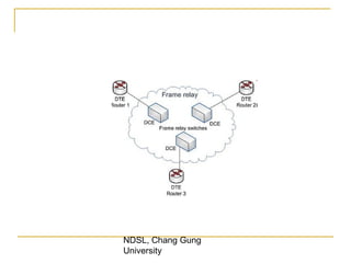
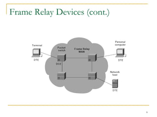
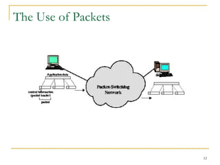
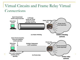
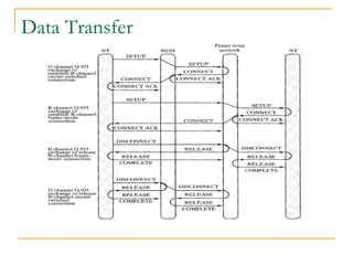
Frame Relay To provide a telecommunication service for cost-efficient data transmission for intermittent traffic between  local area networks  (LANs) and between end-points in a  wide area network  (WAN). Frame Relay puts data in variable-size units called "frames" and leaves any necessary  error-correction  (such as re-transmission of data) up to the end-points.  This speeds up overall data transmission. For most services, the network provides a  permanent virtual circuit  (PVC), which means that the customer sees a continuous, dedicated connection without having to pay for a full-time  leased line ,  while the  service-provider  figures out the route each frame travels to its destination and can charge based on usage.  NDSL, Chang Gung University
Frame Relay has its technical base in the older  X.25 packet-switching  technology, designed for transmitting data on analog voice lines.  Unlike X.25, whose designers expected  analog signals , Frame Relay offers a  fast packet technology , which means that the protocol does not attempt to correct errors.  When a Frame Relay network detects an error in a frame, it simply drops that frame.  The end points have the responsibility for detecting and retransmitting dropped frames. NDSL, Chang Gung University
NDSL, Chang Gung University
Introduction Frame Relay (FR)  is a high-performance WAN protocol that operates at the  physical  and  data link  layers of the OSI reference model. FR originally was designed for use across  Integrated Service Digital Network  (ISDN) interfaces. Today, it is used over a variety of other network  interfaces  as well. FR is an example of a  packet-switched  technology.
What is Frame Relay? “ A packet-switching protocol for connecting devices on a Wide Area Network (WAN) ”  FR networks support data transfer rates at  T-1 (1.544 Mb/s)  T-3 (45 Mb/s) speeds.  In fact, you can think of Frame Relay as a way of utilizing existing T-1 and T-3 lines owned by a service provider.  Most telephone companies now provide FR service for customers who want connections at 56 Kb/s to T-1 speeds. (In Europe, FR’s speeds vary from 64 Kb/s to 2 Mb/s. Frame Relay is quite popular because it is  relatively inexpensive . However, it is being replaced in some areas by faster technologies, such as ATM.
Frame Relay Devices (cont.)
Frame Relay Devices Devices attached to a Frame Relay WAN fall into the following two general categories: Data terminal equipment (DTE) DTEs generally are considered to be terminating equipment for a specific network and typically are located on the premises of a customer. Example of DTE devices are terminals, personal computers, routers, and bridges. Data circuit-terminating equipment (DCE) DCEs are carrier-owned internetworking devices. The purpose of DCE equipments is to provide clocking and switching services in a network, which are the devices that actually transmit data through the WAN.
Frame Relay Devices (cont.) The connection between a DTE device and a DCE device consists of both a  physical layer component (L1)  and a  link layer component (L2) . The physical component defines the mechanical, electrical, functional, and procedural specifications for the connection between the devices.  One of the commonly used physical layer interface specifications is the recommended standard  (RS)-232 .
Serial Point-to-Point Connection Network connections at the CSU/DSU EIA/TIA-232 EIA/TIA-449 EIA-530 V.35 X.21 End user device Service Provider DTE DCE Router connections
Circuit-Switching Long-haul telecom network designed for voice Network resources dedicated to one call Shortcomings when used for data: Inefficient (high idle time) Constant data rate
Packet-Switching Data transmitted in short blocks, or packets Packet length < 1000 octets Each packet contains user data plus control info (routing) Store and forward
The Use of Packets
Advantages with compared to Circuit-Switching Greater line efficiency  (many packets can go over shared link) Data rate conversions Non-blocking under heavy traffic  (but increased delays). When traffic becomes heavy on a circuit-switching network, some calls are blocked. Priorities  can be used.
Disadvantages relative to Circuit-Switching Packets incur  additional delay  with every node they pass through Jitter : variation in packet delay Data overhead  in every packet for routing information, etc Processing overhead  for every packet at every node traversed
Simple Switching Network
Switching Technique Large messages broken up into smaller packets Datagram Each packet sent independently of the others No call setup More reliable (can route around failed nodes or congestion) Virtual circuit Fixed route established before any packets sent No need for routing decision for each packet at each node
Packet Switching: Datagram Approach
Packet Switching: Virtual-Circuit Approach
Virtual Circuits and Frame Relay Virtual Connections
Protocol Architecture
Control Plane Between subscriber and network Separate logical channel used Similar to common channel signaling for circuit switching services Data link layer LAPD (Q.921) Reliable data link control Error and flow control Between user (TE) and network (NT) Used for exchange of Q.933 control signal messages
User Plane End to end functionality Transfer of info between ends LAPF (Link Access Procedure for Frame Mode Bearer Services) Q.922 Frame delimiting, alignment and transparency Frame mux and demux using addressing field Ensure frame is integral number of octets (zero bit insertion/extraction) Ensure frame is neither too long nor short Detection of transmission errors Congestion control functions
LAPF  Core  Formats
User Data Transfer One frame type User data No control frame No inband signaling No sequence numbers No flow nor error control
FRAME RELAY CALL CONTROL Call Control Alternatives In frame relay operation, a user is not connected directly to another user, but rather to a frame handler in the network;  For X.25, a user is connected to a packet handler.
Switched access
Switched access The local exchange does not provide the frame-handling capability.  Switched access must be provided from the user's terminal equipment (TE) to the frame handler  Connection will be a demand connection (set up at the time of the call) or a semi-permanent connection (always available).
Integrated access
Integrated access The user is connected to a pure frame-relaying network or to a switched network  The local exchange provide the frame handling capability.  The user has direct logical access to the frame handler.
Access Connection The connection between the subscriber and the frame handler is access connection.  Once this connection exists, it is possible to multiplex multiple logical connections as frame relay connections,  They may be either on-demand or semipermanent.
Frame Relay Connection The subscriber must established an access connection to a frame handler A frame relay connection, analogous to a packet-switching virtual circuit, must first be established between two users. Each connection has unique data link connection identifier (DLCI).
Data Transfer 1. Establish a logical connection between two end points, and assign a unique DLCI to the connection.  2. Exchange information in data frames. Each frame includes a DLCI field to identify the connection.  3. Release the logical connection.
Frame relay Connection The establishment and release of a logical connection will be carried out in a connection. Exchange of messages over a logical connection is dedicated to call control A frame with DLCI = 0 contains a call control message in the information field. At a minimum, four message types are needed:
Messages SETUP - request the establishment of a logical connection if it accepts the connection CONNECT - assign the DLCI by choosing an unused value and including this value in the SETUP message; otherwise, the DLCI value is assigned by the accepting side in the CONNECT message. RELEASE - to clear a logical connection RELEASE COMPLETE - Not accept a connection
Messages
Connection Exchanges involved for switched access to a frame handler The calling user must establish a circuit-switched connection to a frame handler  Done with the usual SETUP, CONNECT and CONNECT ACK messages,
Data Transfer

Frame relay

  • 1.
    Frame Relay Toprovide a telecommunication service for cost-efficient data transmission for intermittent traffic between local area networks (LANs) and between end-points in a wide area network (WAN). Frame Relay puts data in variable-size units called &quot;frames&quot; and leaves any necessary error-correction (such as re-transmission of data) up to the end-points. This speeds up overall data transmission. For most services, the network provides a permanent virtual circuit (PVC), which means that the customer sees a continuous, dedicated connection without having to pay for a full-time leased line , while the service-provider figures out the route each frame travels to its destination and can charge based on usage. NDSL, Chang Gung University
  • 2.
    Frame Relay hasits technical base in the older X.25 packet-switching technology, designed for transmitting data on analog voice lines. Unlike X.25, whose designers expected analog signals , Frame Relay offers a fast packet technology , which means that the protocol does not attempt to correct errors. When a Frame Relay network detects an error in a frame, it simply drops that frame. The end points have the responsibility for detecting and retransmitting dropped frames. NDSL, Chang Gung University
  • 3.
    NDSL, Chang GungUniversity
  • 4.
    Introduction Frame Relay(FR) is a high-performance WAN protocol that operates at the physical and data link layers of the OSI reference model. FR originally was designed for use across Integrated Service Digital Network (ISDN) interfaces. Today, it is used over a variety of other network interfaces as well. FR is an example of a packet-switched technology.
  • 5.
    What is FrameRelay? “ A packet-switching protocol for connecting devices on a Wide Area Network (WAN) ” FR networks support data transfer rates at T-1 (1.544 Mb/s) T-3 (45 Mb/s) speeds. In fact, you can think of Frame Relay as a way of utilizing existing T-1 and T-3 lines owned by a service provider. Most telephone companies now provide FR service for customers who want connections at 56 Kb/s to T-1 speeds. (In Europe, FR’s speeds vary from 64 Kb/s to 2 Mb/s. Frame Relay is quite popular because it is relatively inexpensive . However, it is being replaced in some areas by faster technologies, such as ATM.
  • 6.
  • 7.
    Frame Relay DevicesDevices attached to a Frame Relay WAN fall into the following two general categories: Data terminal equipment (DTE) DTEs generally are considered to be terminating equipment for a specific network and typically are located on the premises of a customer. Example of DTE devices are terminals, personal computers, routers, and bridges. Data circuit-terminating equipment (DCE) DCEs are carrier-owned internetworking devices. The purpose of DCE equipments is to provide clocking and switching services in a network, which are the devices that actually transmit data through the WAN.
  • 8.
    Frame Relay Devices(cont.) The connection between a DTE device and a DCE device consists of both a physical layer component (L1) and a link layer component (L2) . The physical component defines the mechanical, electrical, functional, and procedural specifications for the connection between the devices. One of the commonly used physical layer interface specifications is the recommended standard (RS)-232 .
  • 9.
    Serial Point-to-Point ConnectionNetwork connections at the CSU/DSU EIA/TIA-232 EIA/TIA-449 EIA-530 V.35 X.21 End user device Service Provider DTE DCE Router connections
  • 10.
    Circuit-Switching Long-haul telecomnetwork designed for voice Network resources dedicated to one call Shortcomings when used for data: Inefficient (high idle time) Constant data rate
  • 11.
    Packet-Switching Data transmittedin short blocks, or packets Packet length < 1000 octets Each packet contains user data plus control info (routing) Store and forward
  • 12.
    The Use ofPackets
  • 13.
    Advantages with comparedto Circuit-Switching Greater line efficiency (many packets can go over shared link) Data rate conversions Non-blocking under heavy traffic (but increased delays). When traffic becomes heavy on a circuit-switching network, some calls are blocked. Priorities can be used.
  • 14.
    Disadvantages relative toCircuit-Switching Packets incur additional delay with every node they pass through Jitter : variation in packet delay Data overhead in every packet for routing information, etc Processing overhead for every packet at every node traversed
  • 15.
  • 16.
    Switching Technique Largemessages broken up into smaller packets Datagram Each packet sent independently of the others No call setup More reliable (can route around failed nodes or congestion) Virtual circuit Fixed route established before any packets sent No need for routing decision for each packet at each node
  • 17.
  • 18.
  • 19.
    Virtual Circuits andFrame Relay Virtual Connections
  • 20.
  • 21.
    Control Plane Betweensubscriber and network Separate logical channel used Similar to common channel signaling for circuit switching services Data link layer LAPD (Q.921) Reliable data link control Error and flow control Between user (TE) and network (NT) Used for exchange of Q.933 control signal messages
  • 22.
    User Plane Endto end functionality Transfer of info between ends LAPF (Link Access Procedure for Frame Mode Bearer Services) Q.922 Frame delimiting, alignment and transparency Frame mux and demux using addressing field Ensure frame is integral number of octets (zero bit insertion/extraction) Ensure frame is neither too long nor short Detection of transmission errors Congestion control functions
  • 23.
    LAPF Core Formats
  • 24.
    User Data TransferOne frame type User data No control frame No inband signaling No sequence numbers No flow nor error control
  • 25.
    FRAME RELAY CALLCONTROL Call Control Alternatives In frame relay operation, a user is not connected directly to another user, but rather to a frame handler in the network; For X.25, a user is connected to a packet handler.
  • 26.
  • 27.
    Switched access Thelocal exchange does not provide the frame-handling capability. Switched access must be provided from the user's terminal equipment (TE) to the frame handler Connection will be a demand connection (set up at the time of the call) or a semi-permanent connection (always available).
  • 28.
  • 29.
    Integrated access Theuser is connected to a pure frame-relaying network or to a switched network The local exchange provide the frame handling capability. The user has direct logical access to the frame handler.
  • 30.
    Access Connection Theconnection between the subscriber and the frame handler is access connection. Once this connection exists, it is possible to multiplex multiple logical connections as frame relay connections, They may be either on-demand or semipermanent.
  • 31.
    Frame Relay ConnectionThe subscriber must established an access connection to a frame handler A frame relay connection, analogous to a packet-switching virtual circuit, must first be established between two users. Each connection has unique data link connection identifier (DLCI).
  • 32.
    Data Transfer 1.Establish a logical connection between two end points, and assign a unique DLCI to the connection. 2. Exchange information in data frames. Each frame includes a DLCI field to identify the connection. 3. Release the logical connection.
  • 33.
    Data Transfer 1.Establish a logical connection between two end points, and assign a unique DLCI to the connection. 2. Exchange information in data frames. Each frame includes a DLCI field to identify the connection. 3. Release the logical connection.
  • 34.
    Frame relay ConnectionThe establishment and release of a logical connection will be carried out in a connection. Exchange of messages over a logical connection is dedicated to call control A frame with DLCI = 0 contains a call control message in the information field. At a minimum, four message types are needed:
  • 35.
    Messages SETUP -request the establishment of a logical connection if it accepts the connection CONNECT - assign the DLCI by choosing an unused value and including this value in the SETUP message; otherwise, the DLCI value is assigned by the accepting side in the CONNECT message. RELEASE - to clear a logical connection RELEASE COMPLETE - Not accept a connection
  • 36.
  • 37.
    Connection Exchanges involvedfor switched access to a frame handler The calling user must establish a circuit-switched connection to a frame handler Done with the usual SETUP, CONNECT and CONNECT ACK messages,
  • 38.

Editor's Notes

  • #5 Protocols and the TCP/IP Suite Chapter 2
  • #6 Protocols and the TCP/IP Suite Chapter 2
  • #7 Protocols and the TCP/IP Suite Chapter 2
  • #8 Protocols and the TCP/IP Suite Chapter 2
  • #9 Protocols and the TCP/IP Suite Chapter 2
  • #10 Protocols and the TCP/IP Suite Chapter 2
  • #11 Protocols and the TCP/IP Suite Chapter 2
  • #12 Protocols and the TCP/IP Suite Chapter 2
  • #13 Protocols and the TCP/IP Suite Chapter 2
  • #14 Protocols and the TCP/IP Suite Chapter 2
  • #15 Protocols and the TCP/IP Suite Chapter 2
  • #16 Protocols and the TCP/IP Suite Chapter 2
  • #17 Protocols and the TCP/IP Suite Chapter 2
  • #18 Protocols and the TCP/IP Suite Chapter 2
  • #19 Protocols and the TCP/IP Suite Chapter 2
  • #20 Protocols and the TCP/IP Suite Chapter 2
  • #21 Protocols and the TCP/IP Suite Chapter 2
  • #22 Protocols and the TCP/IP Suite Chapter 2
  • #23 Protocols and the TCP/IP Suite Chapter 2
  • #24 Protocols and the TCP/IP Suite Chapter 2
  • #25 Protocols and the TCP/IP Suite Chapter 2