Downloaded 860 times
![Multi-Protocol Label Switching: Basics & Applications Dr. Vishal Sharma Email: [email_address] Web: http://www.metanoia-inc.com Metanoia, Inc. Critical Systems Thinking™ © Copyright 2002-2005 All Rights Reserved](https://image.slidesharecdn.com/mtnlmplstutorialdrvishalsharma20050426-13099618377946-phpapp01-110706092342-phpapp01/75/Multi-Protocol-Label-Switching-Basics-and-Applications-1-2048.jpg)
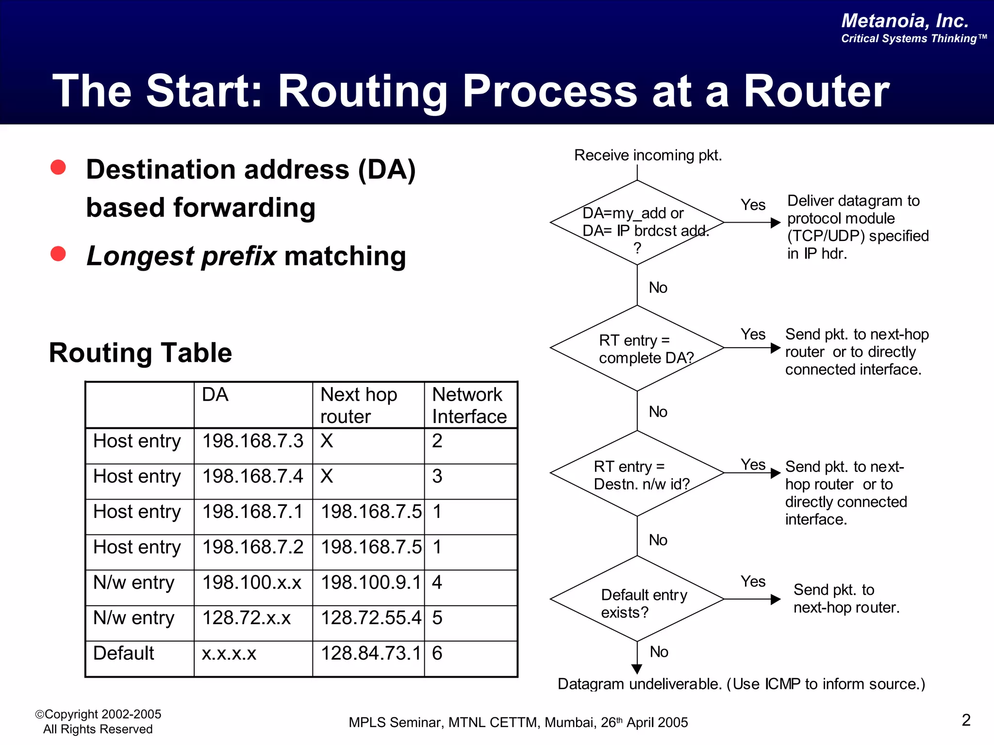
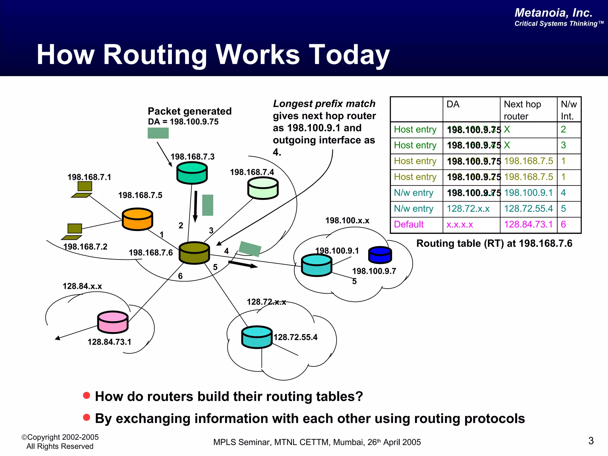
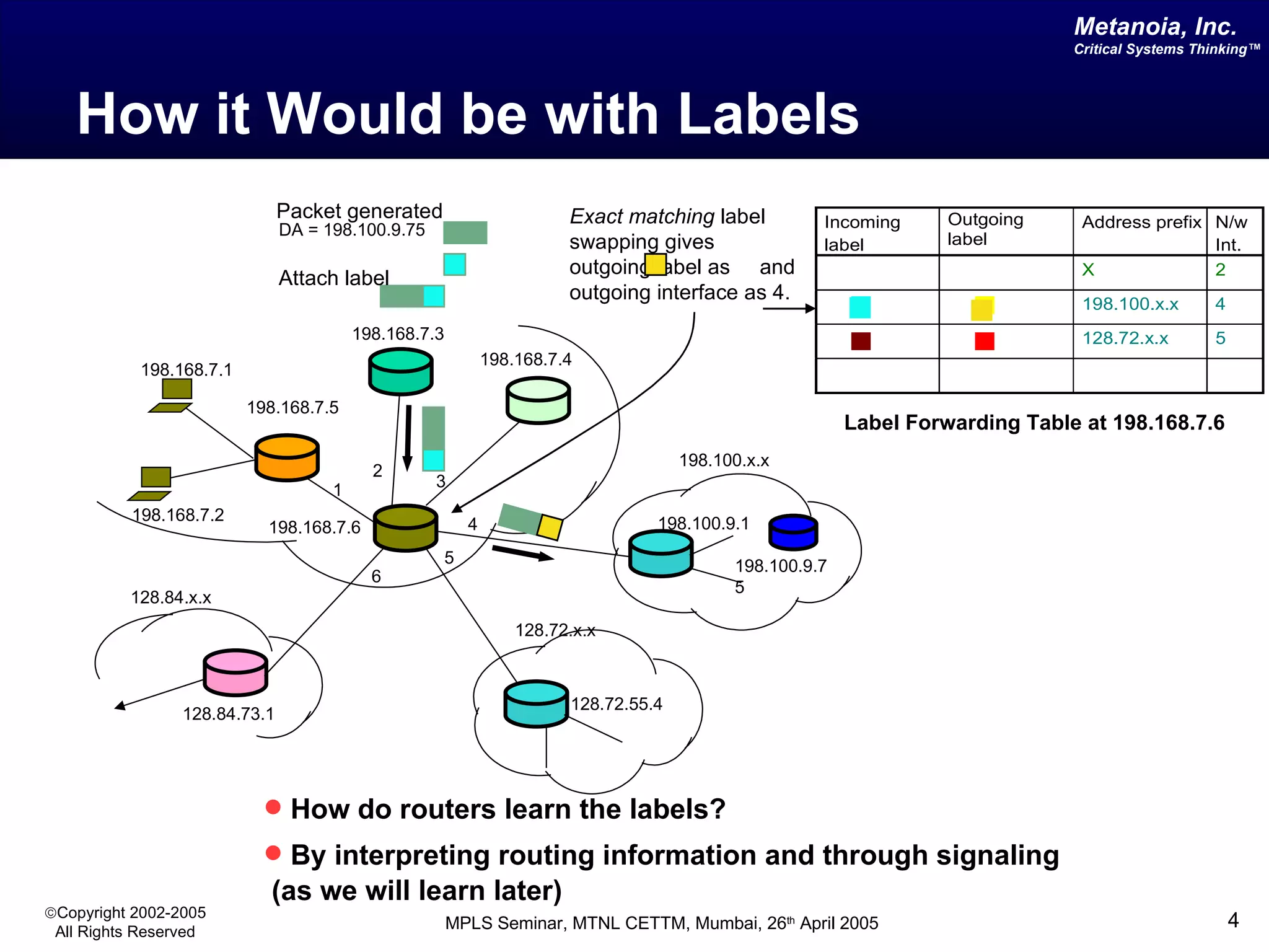
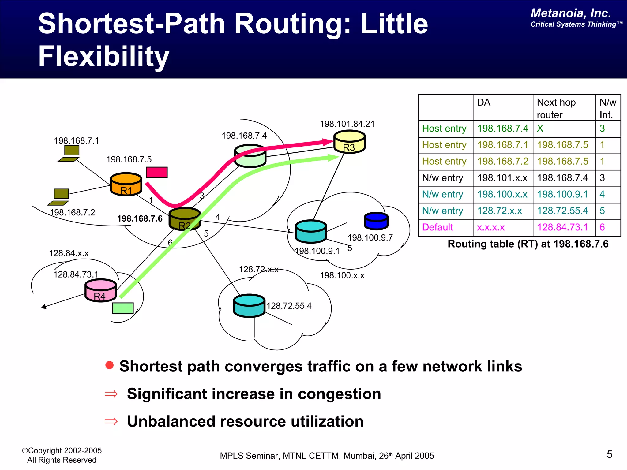
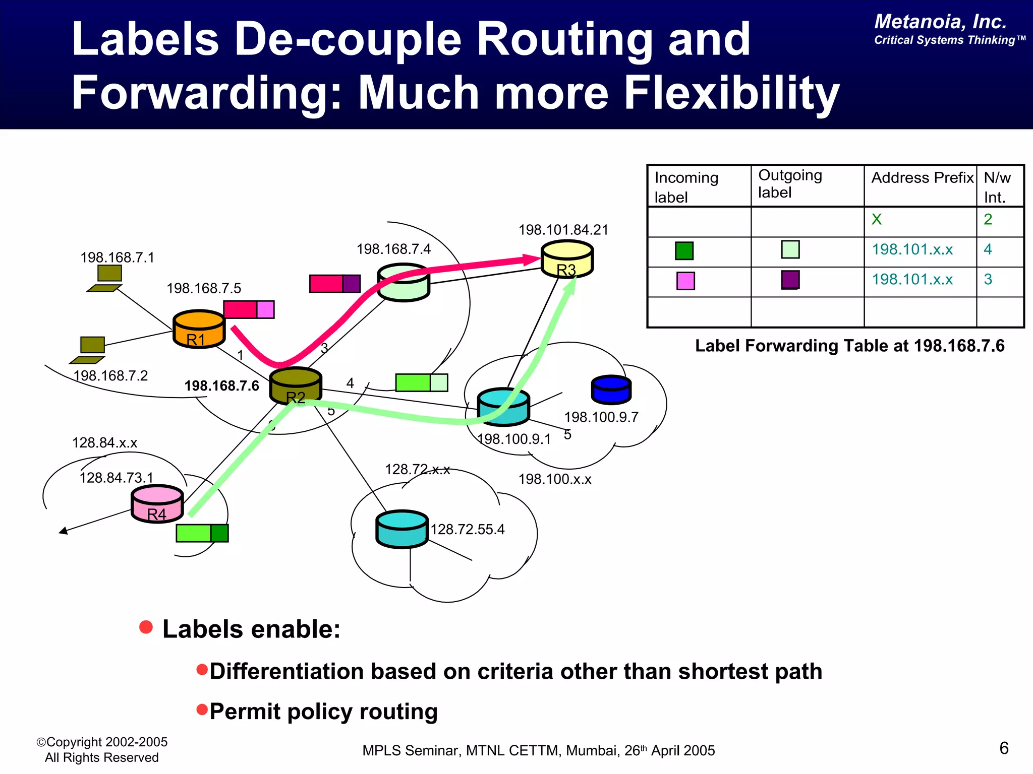
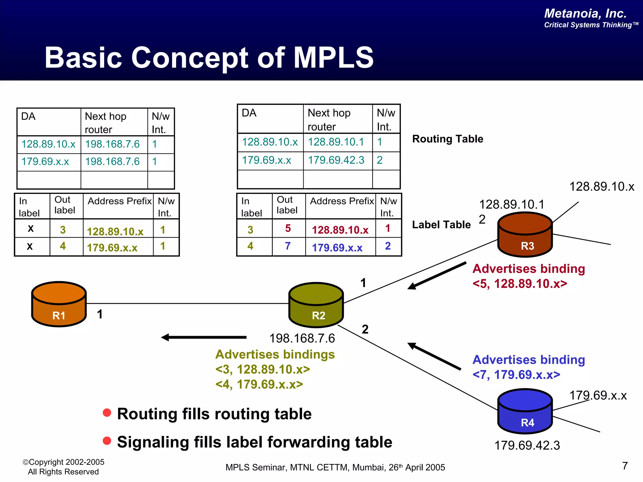
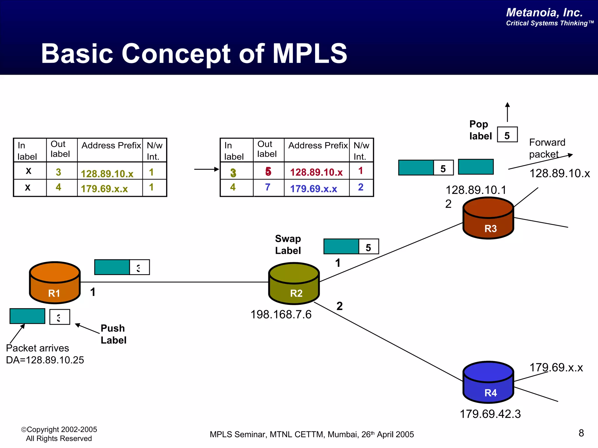
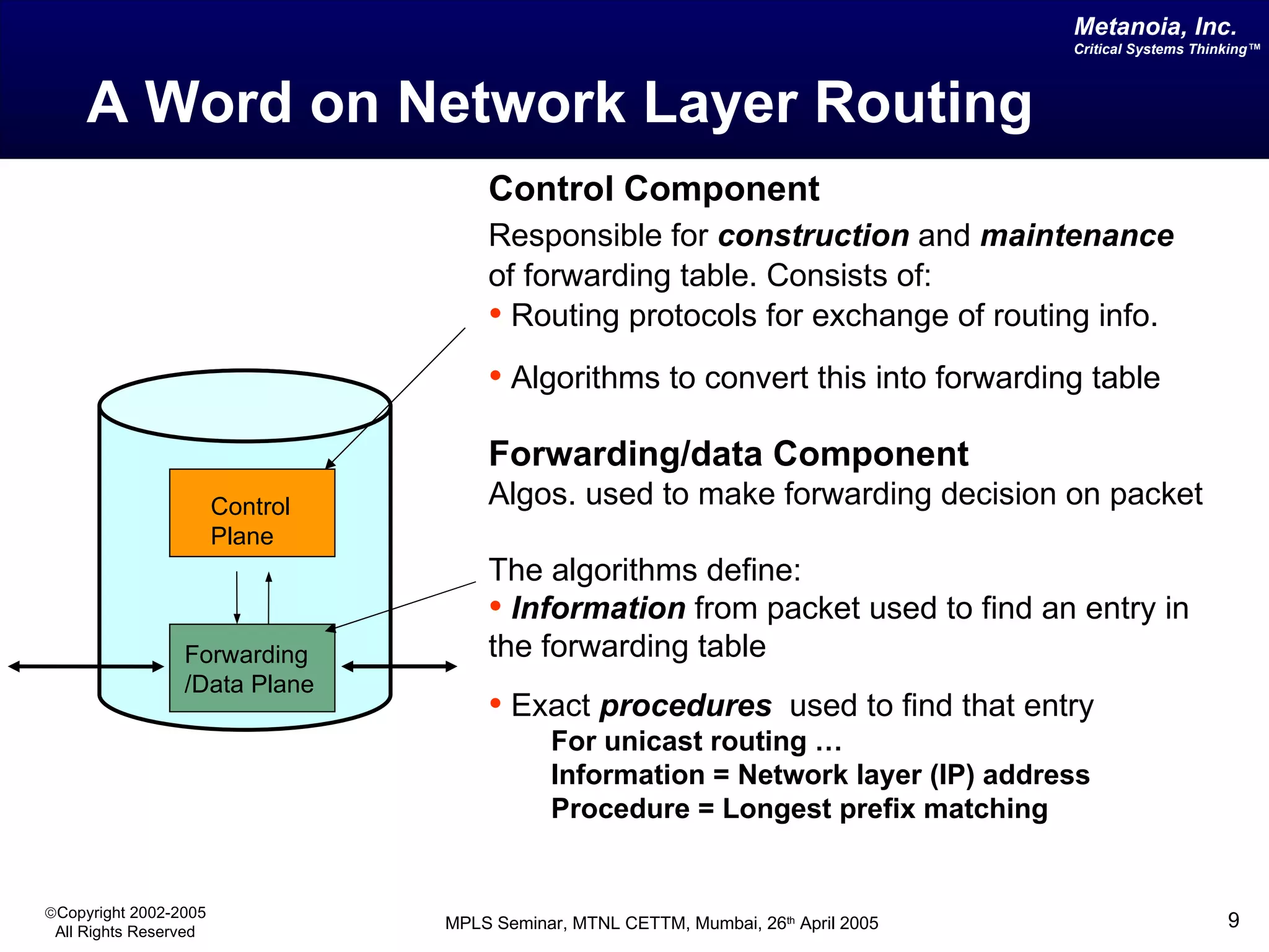
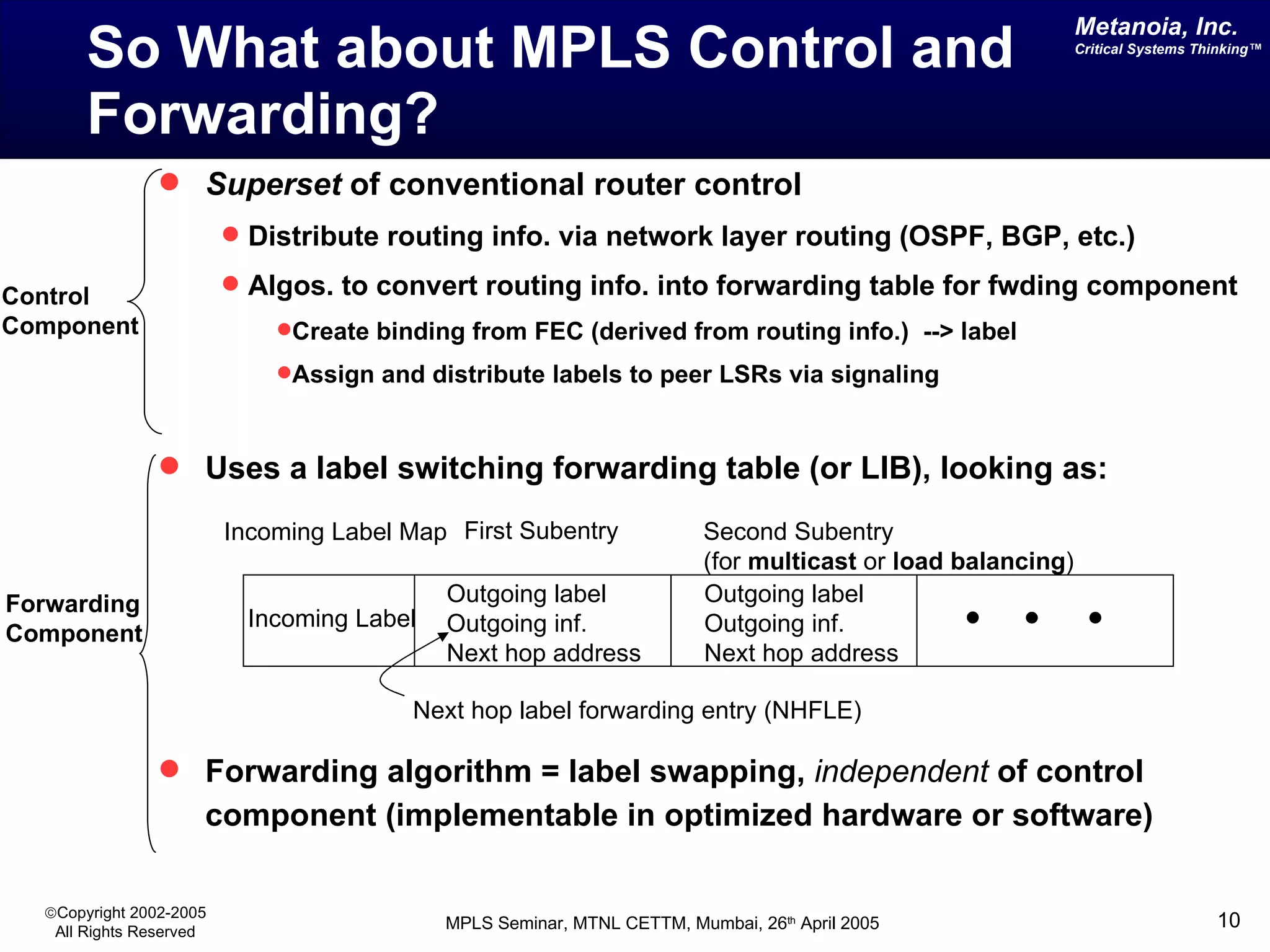
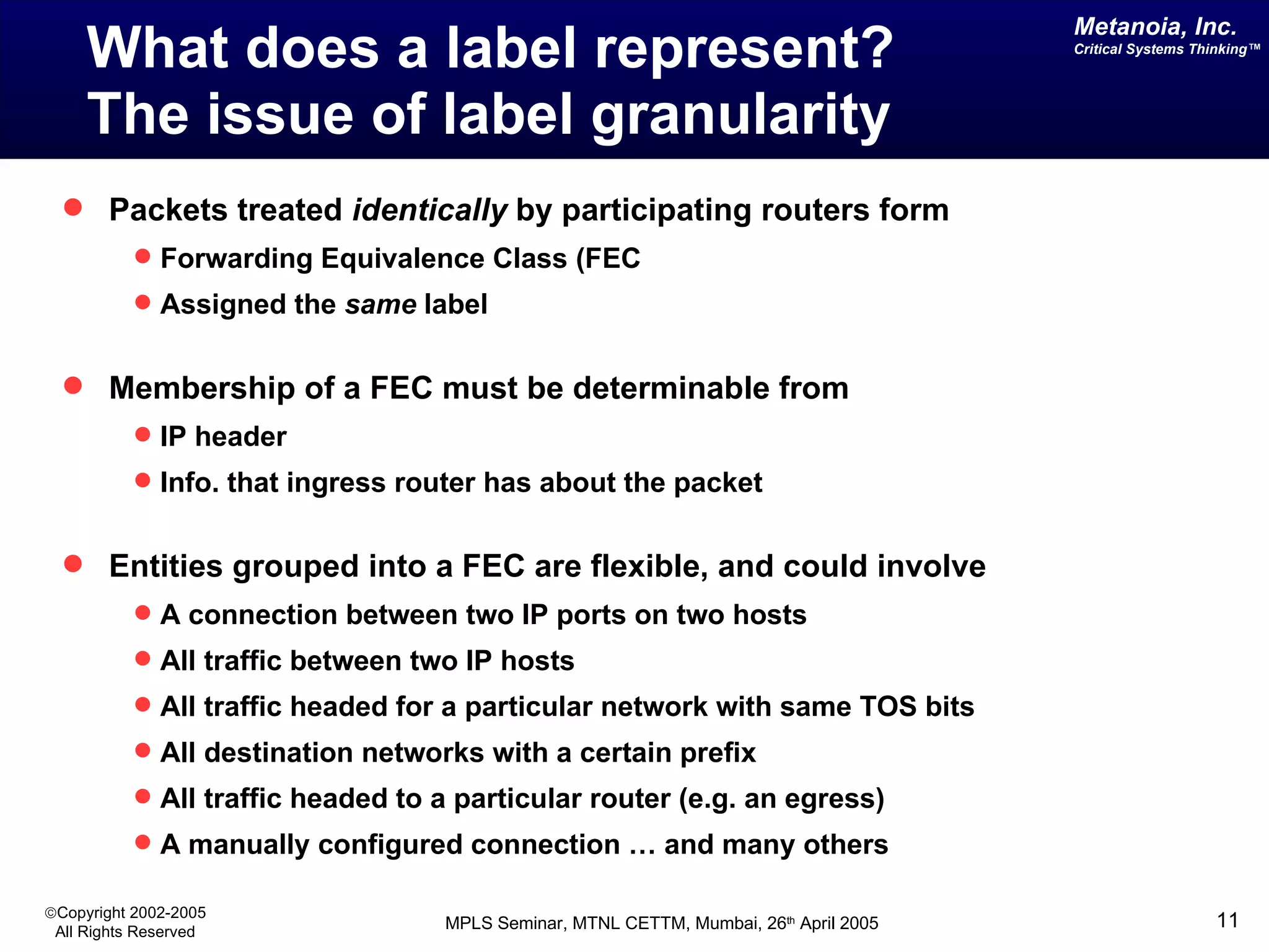
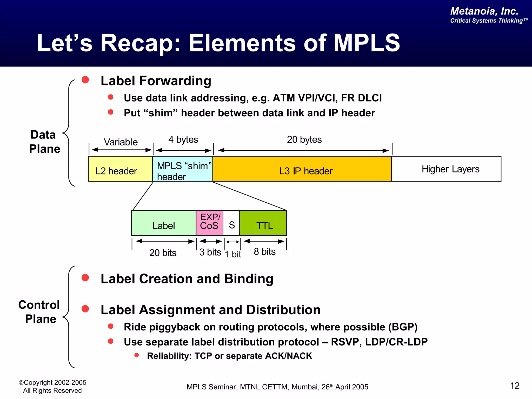
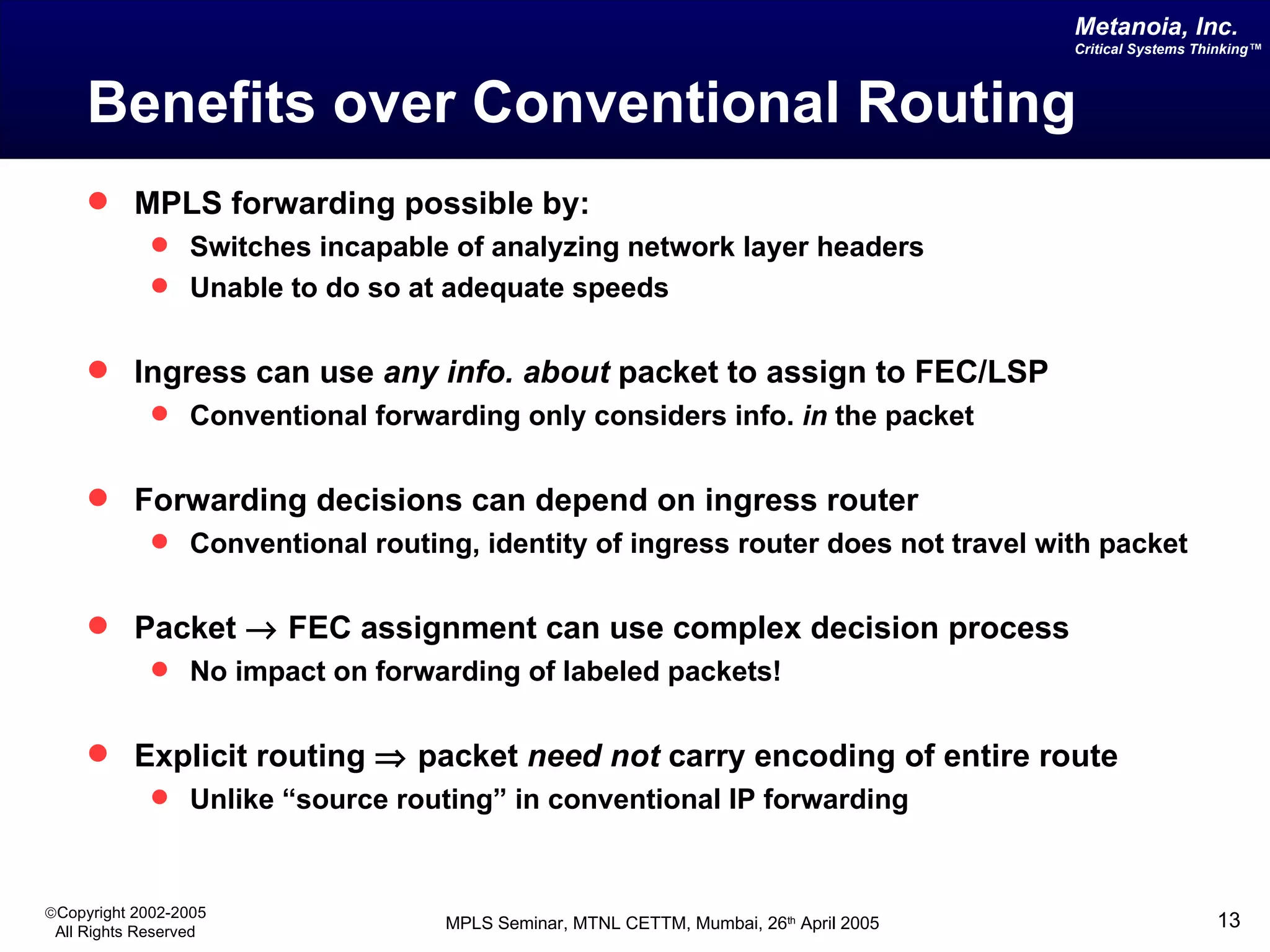
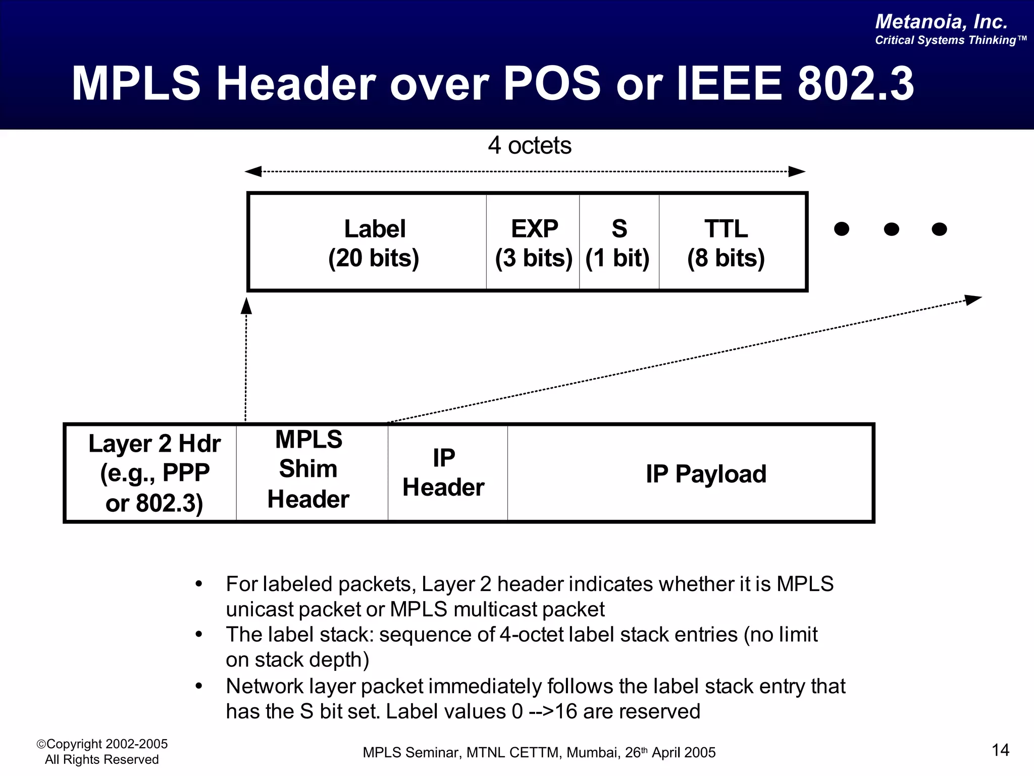
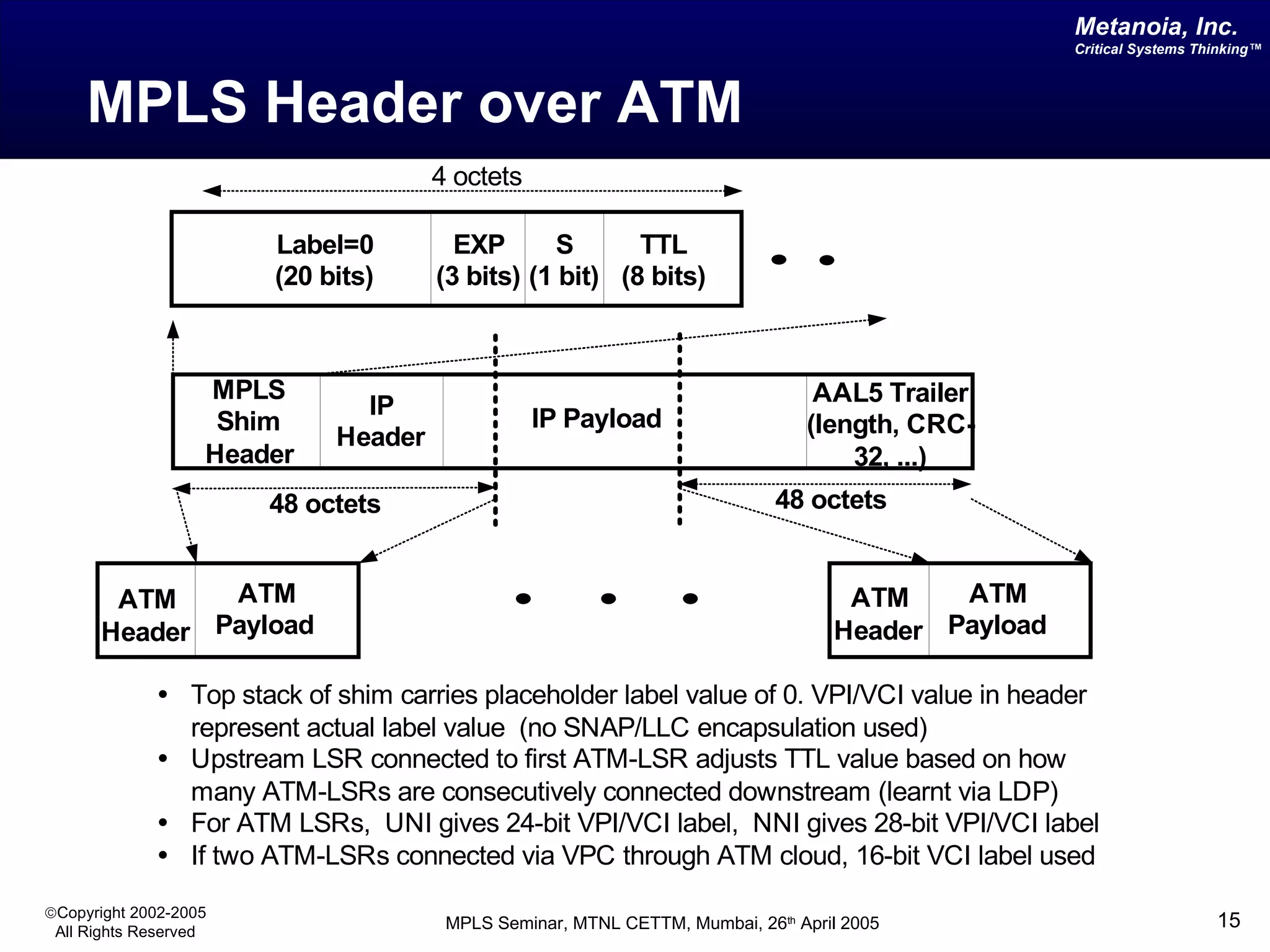
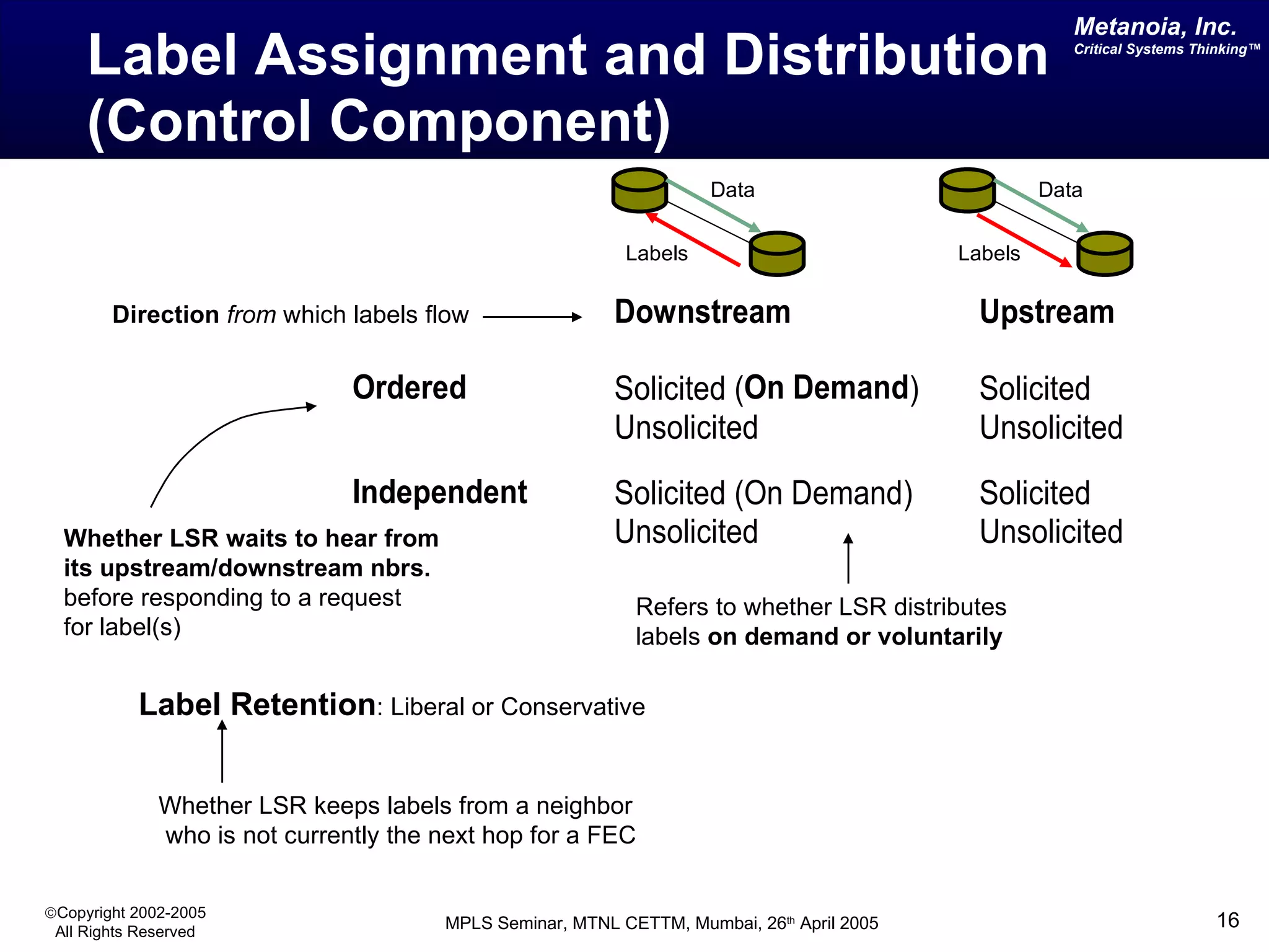
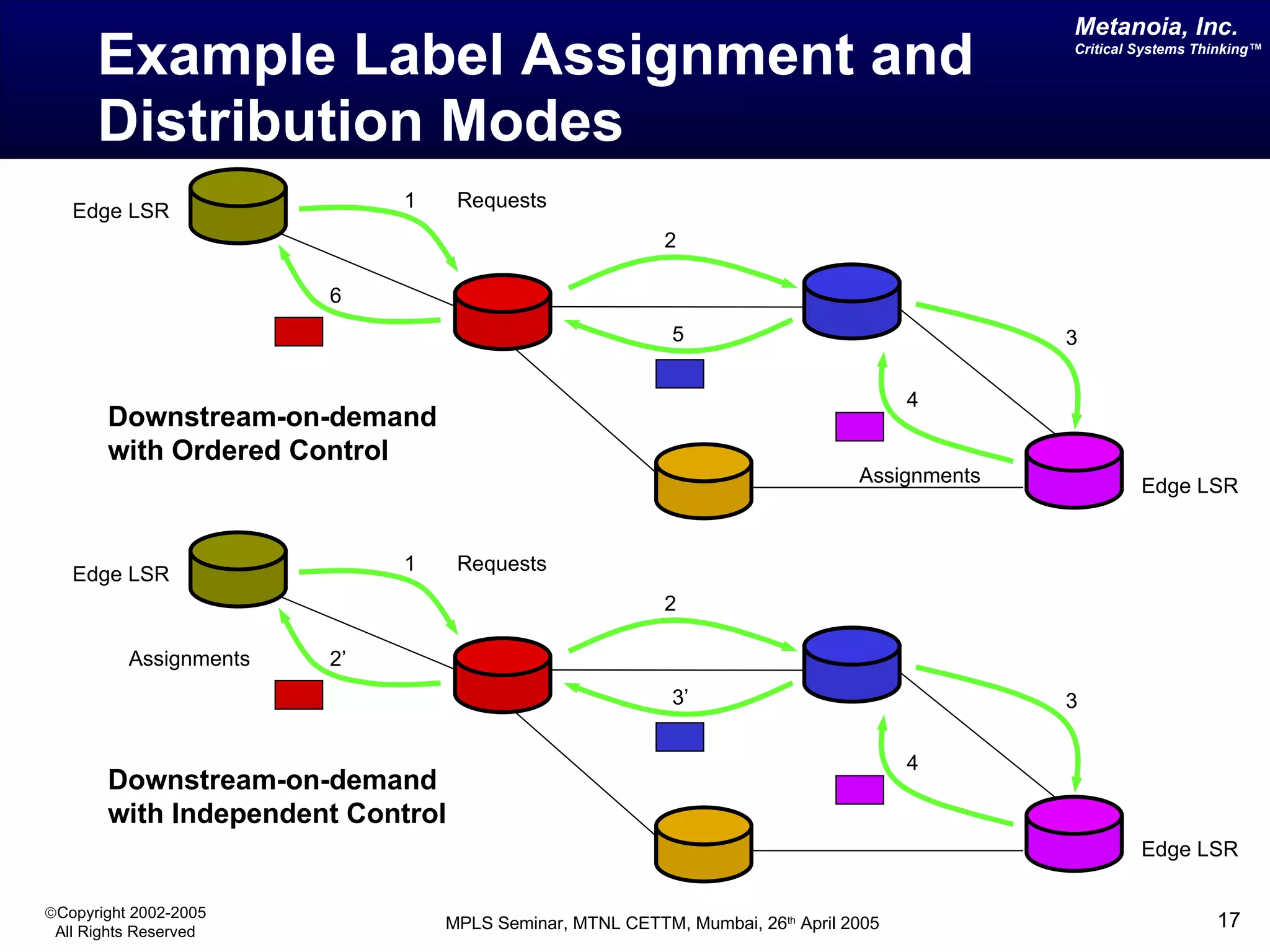
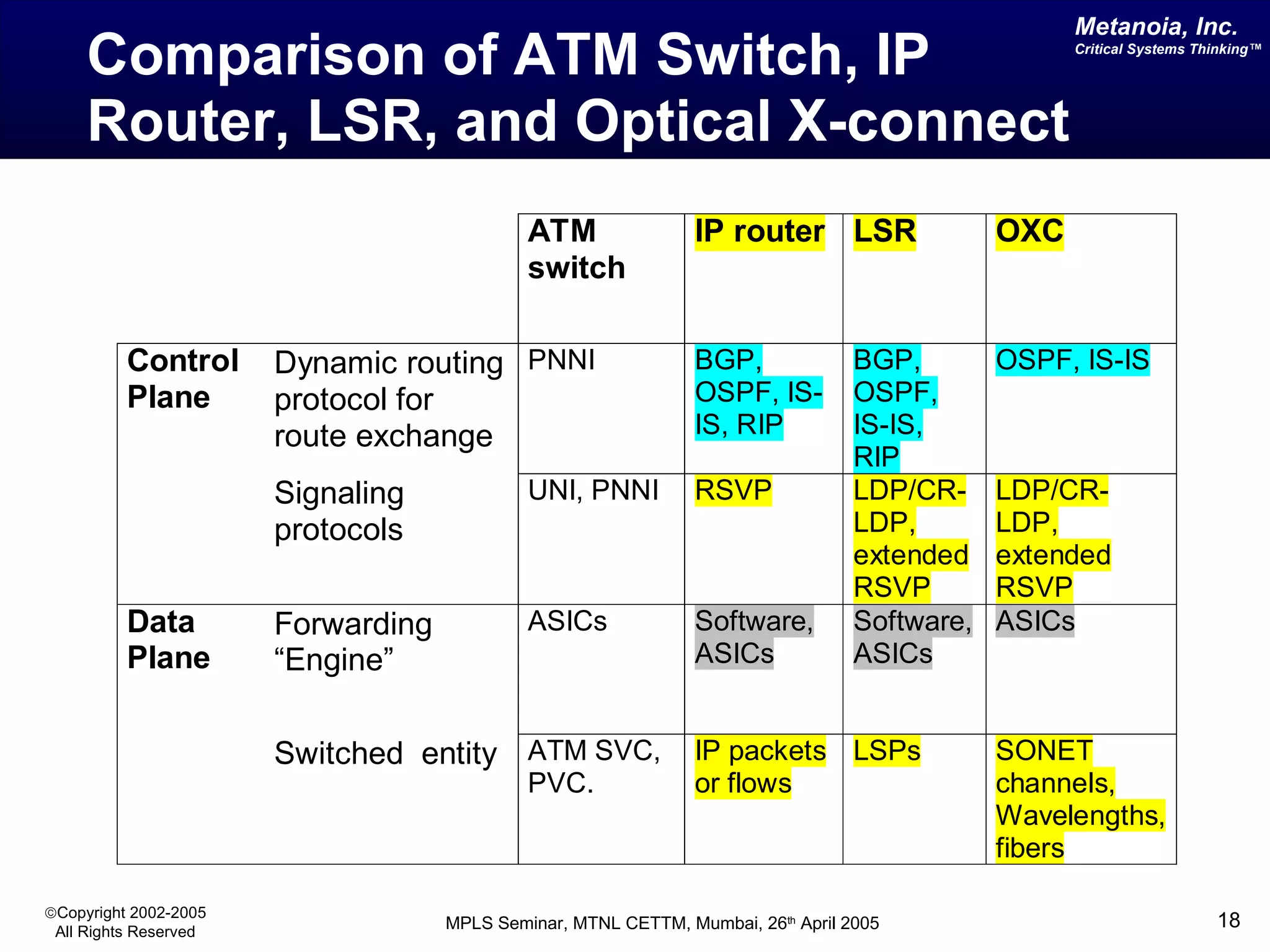
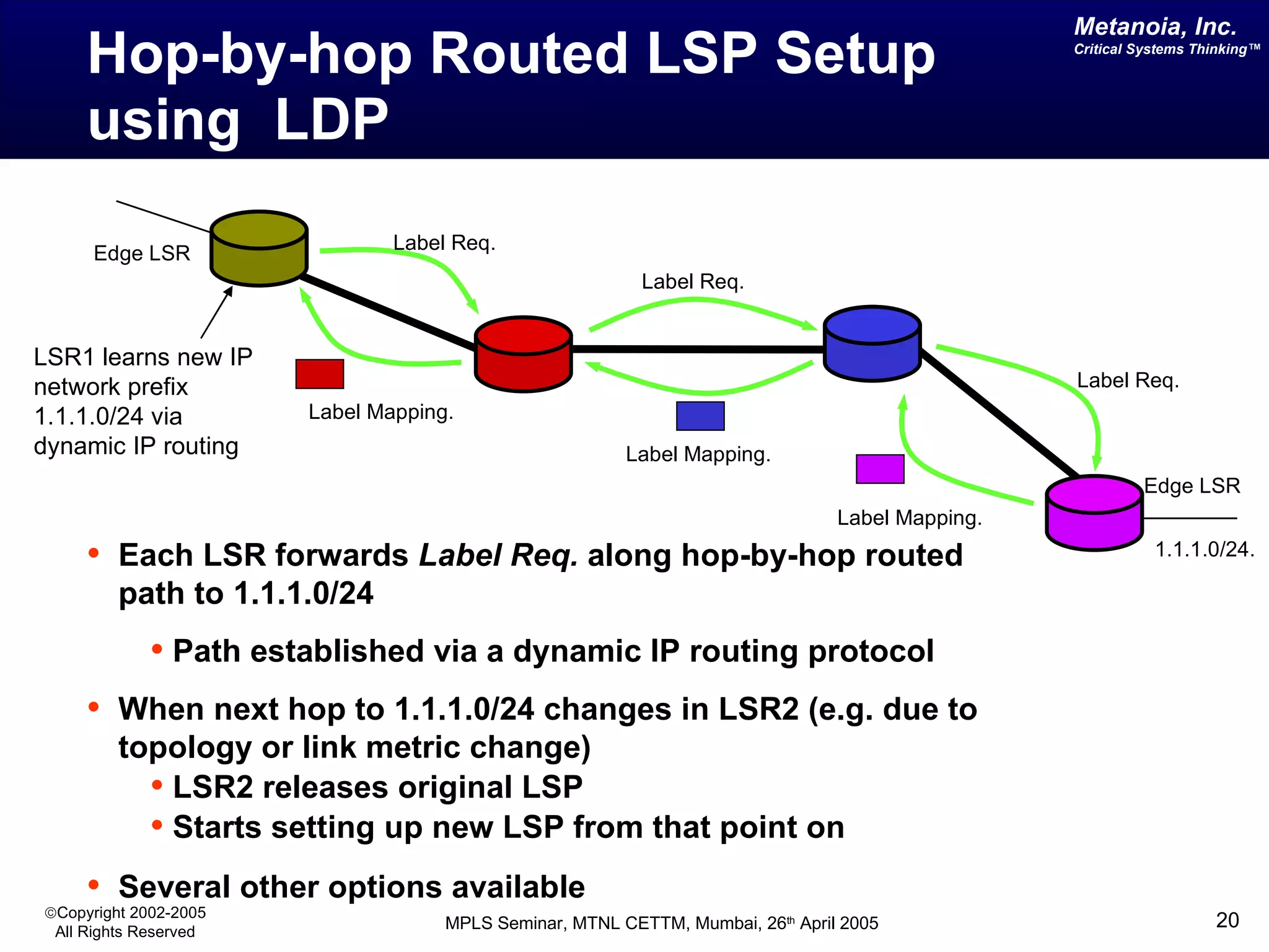
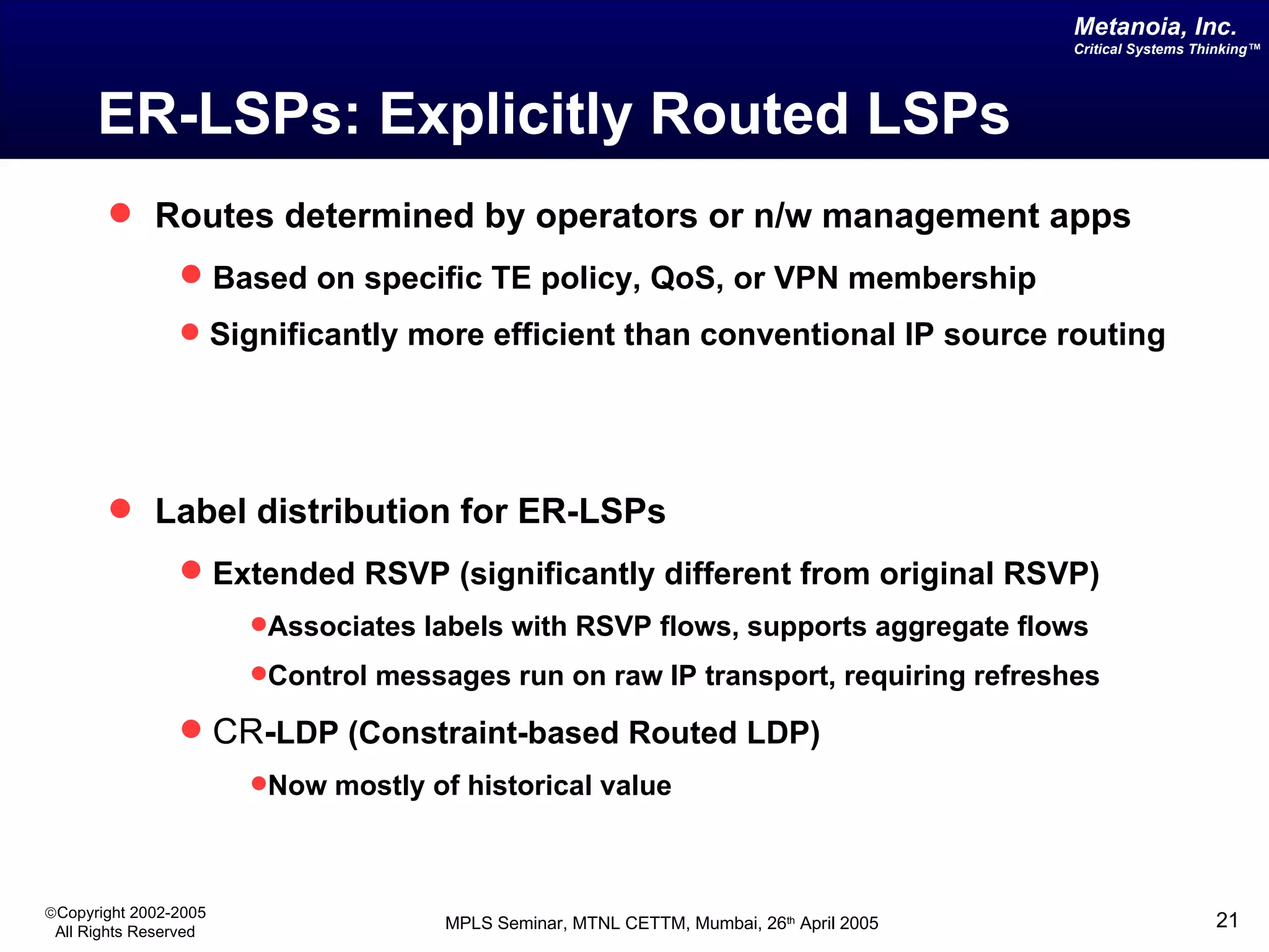
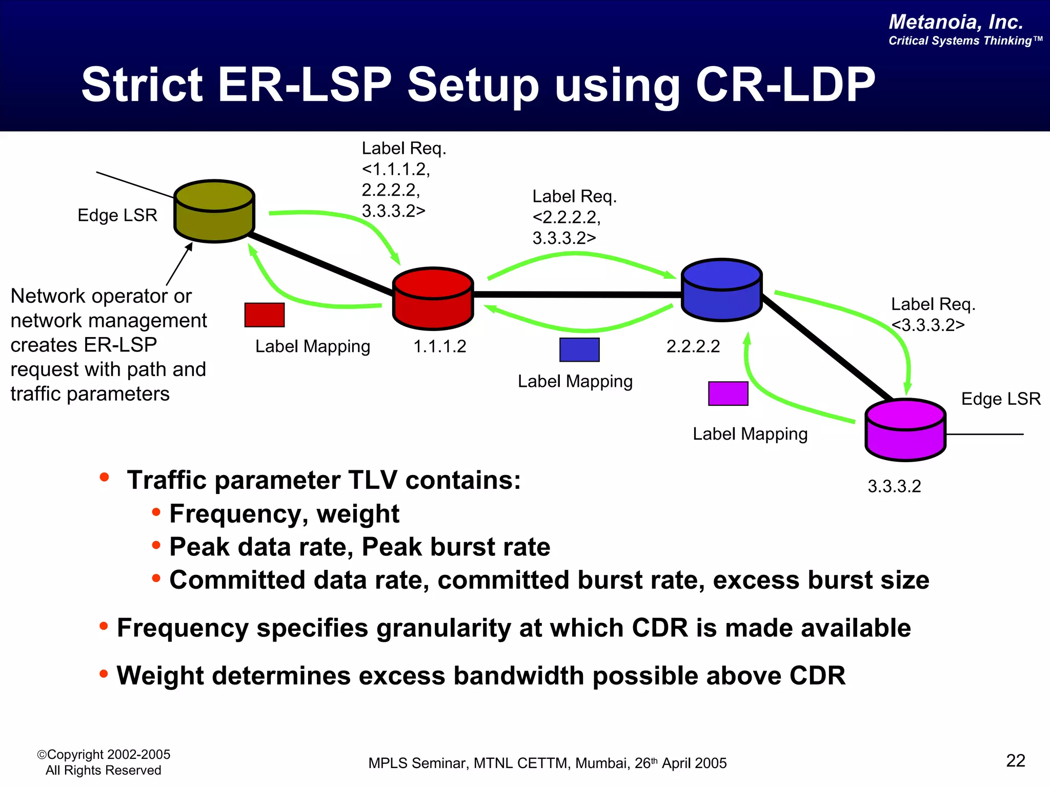
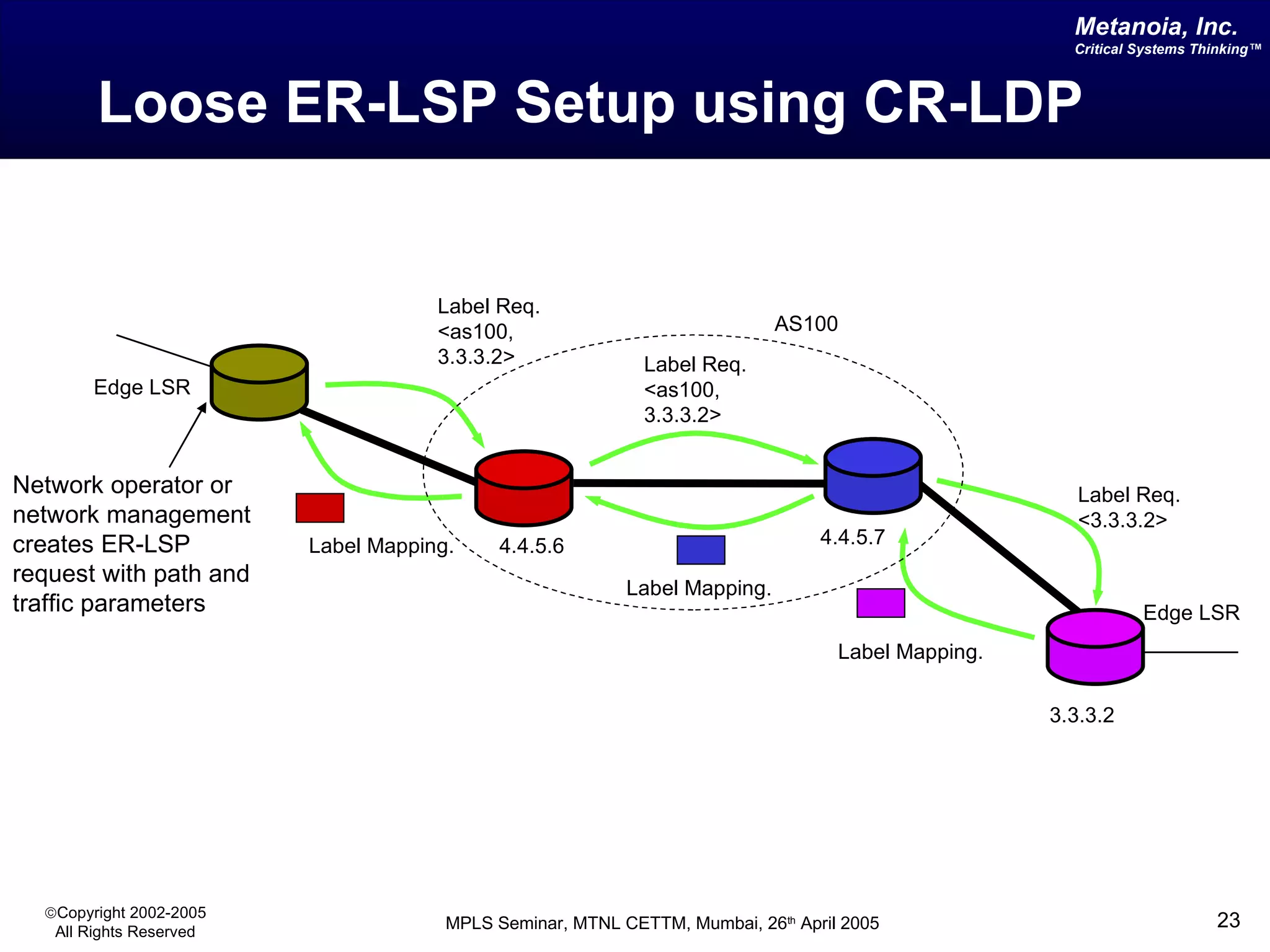
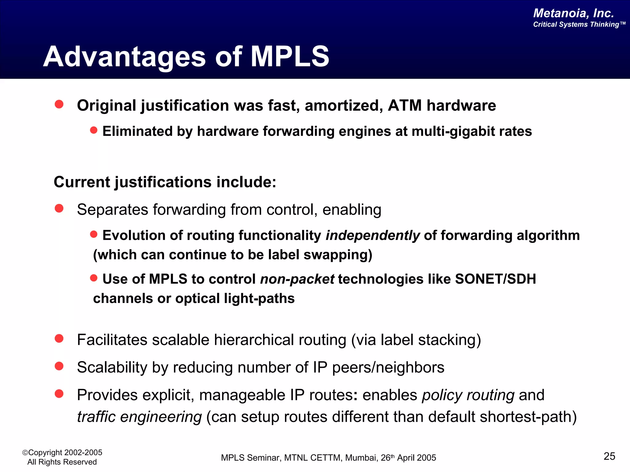
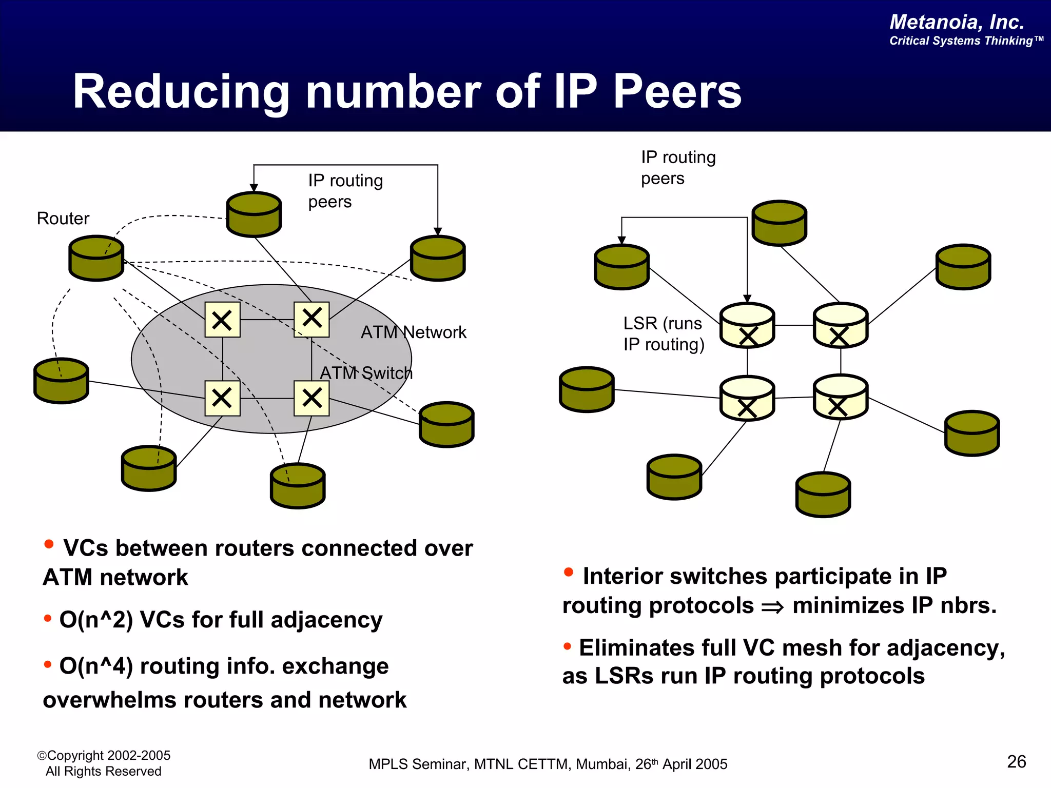
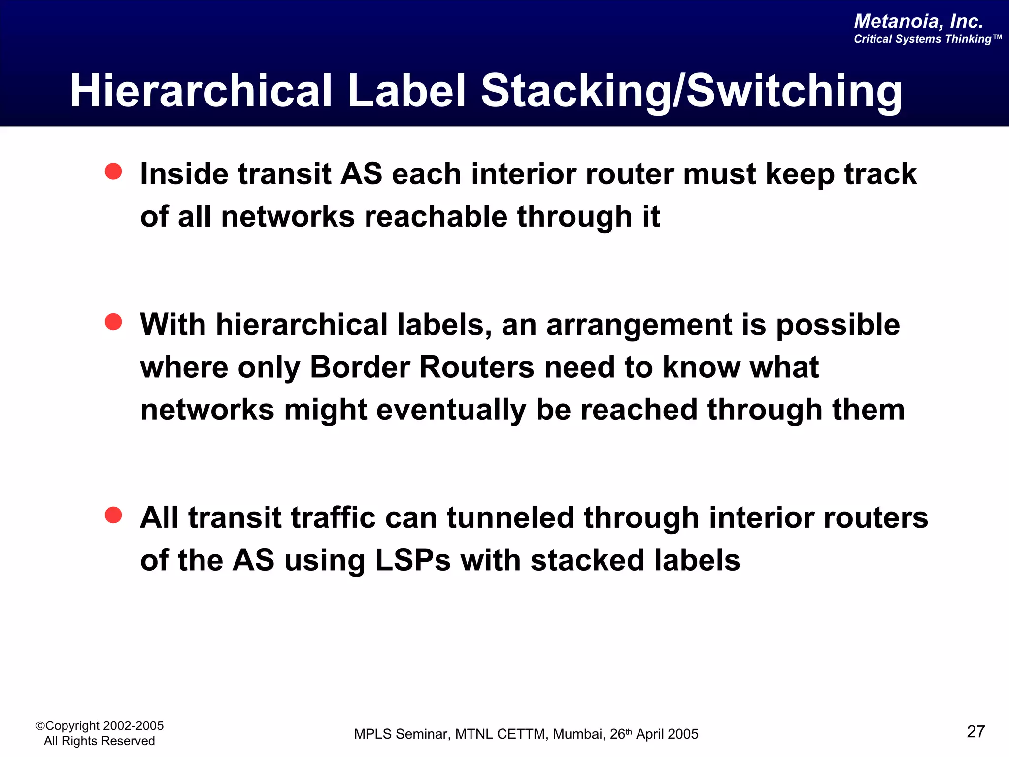
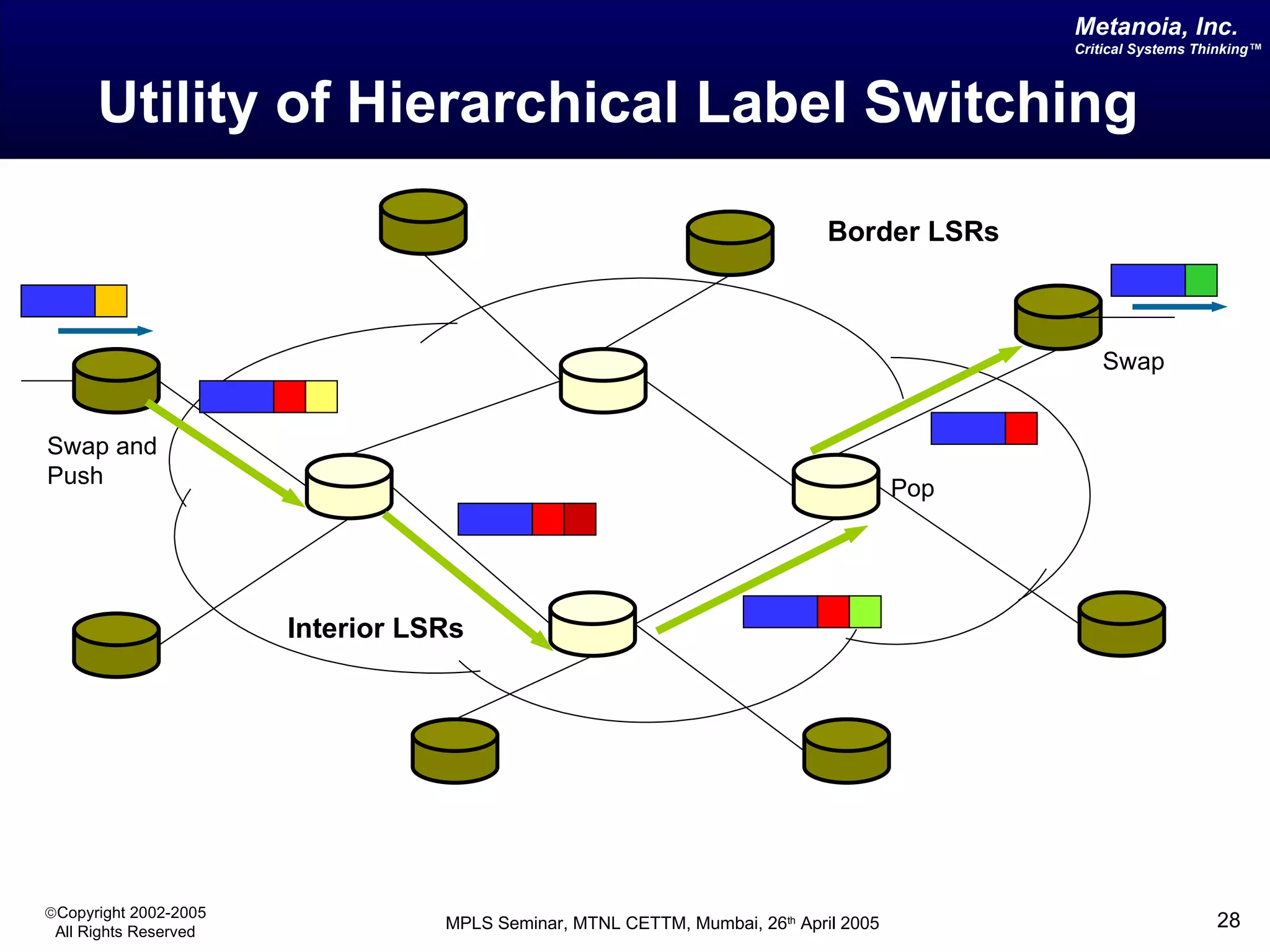
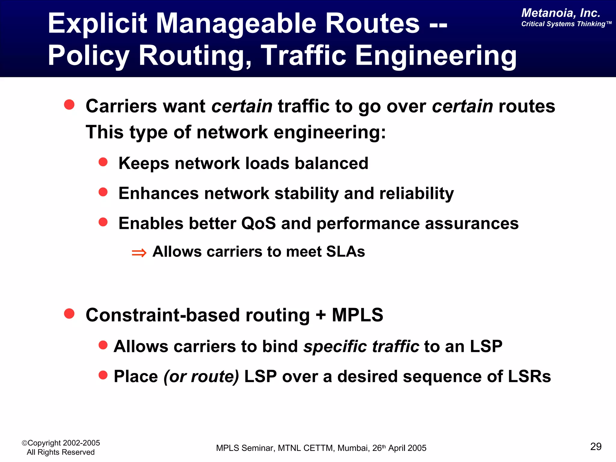
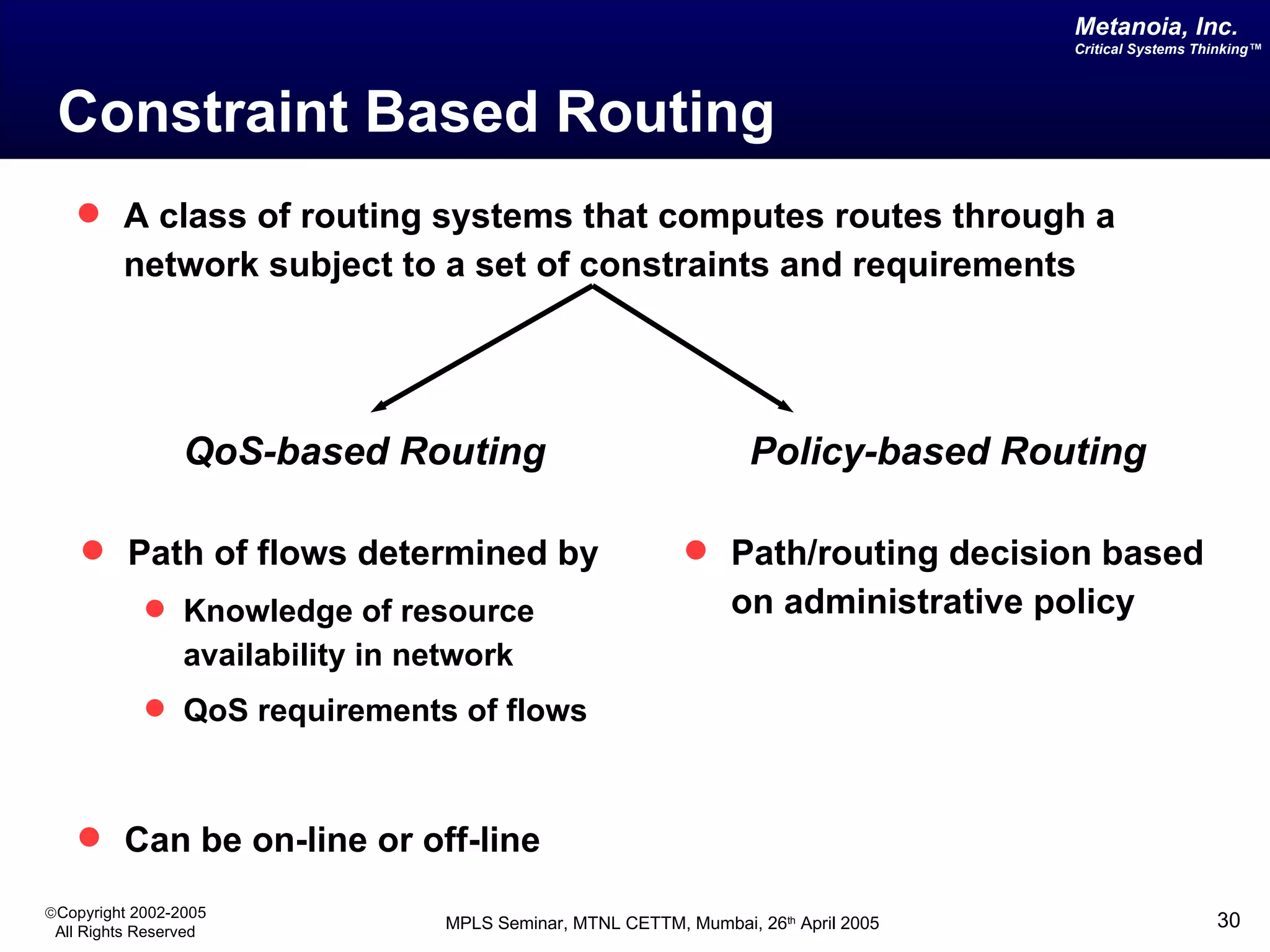
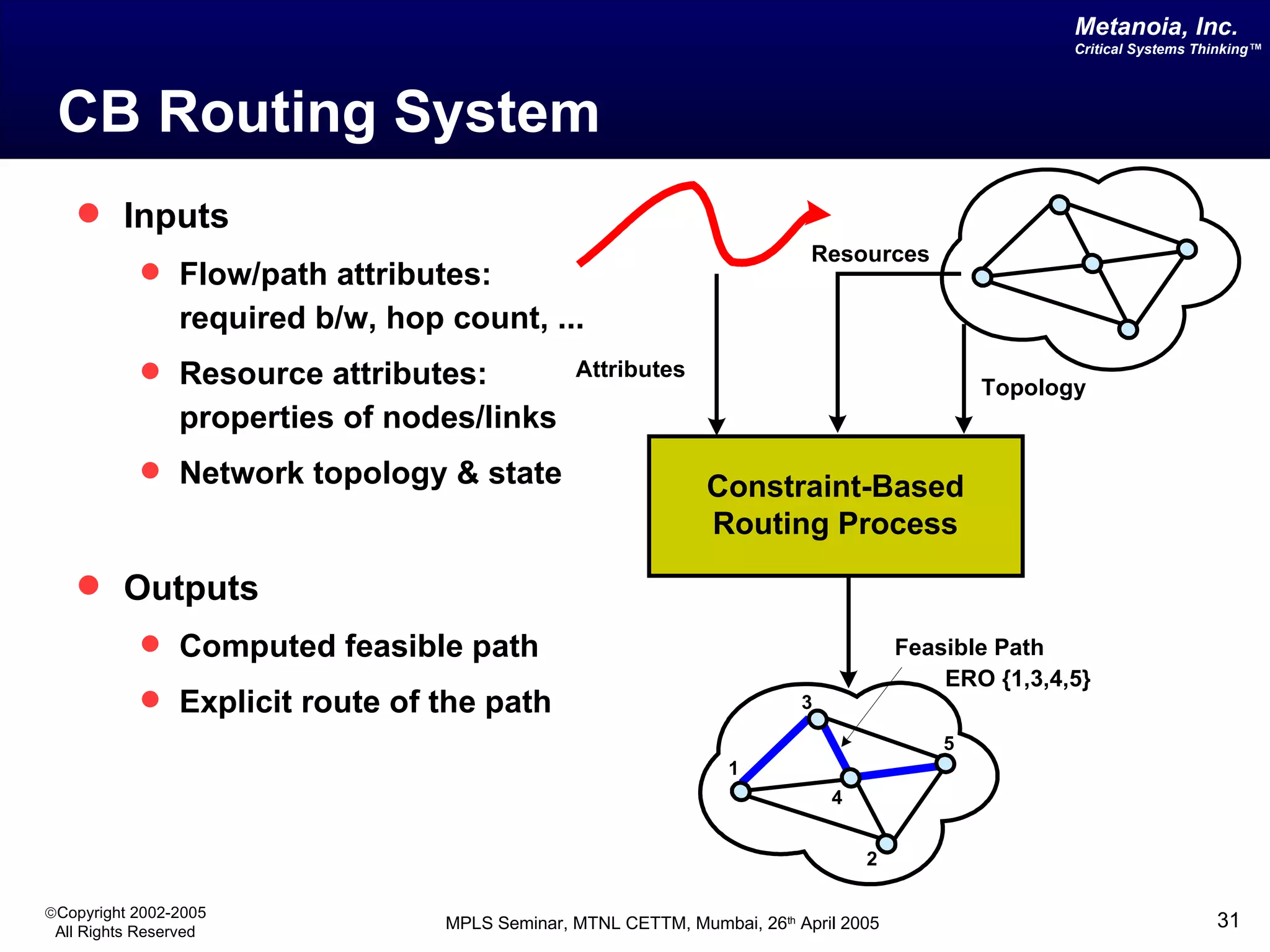
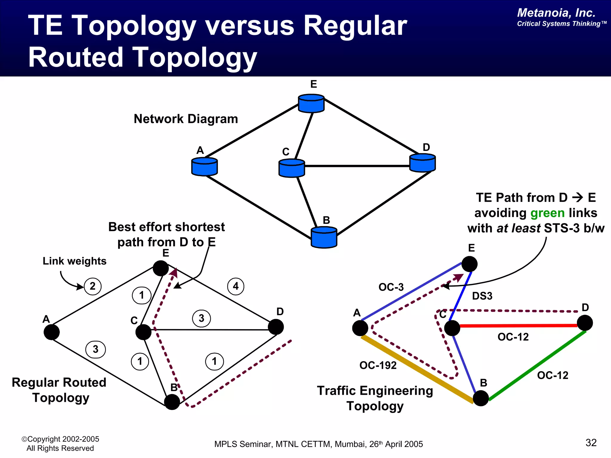
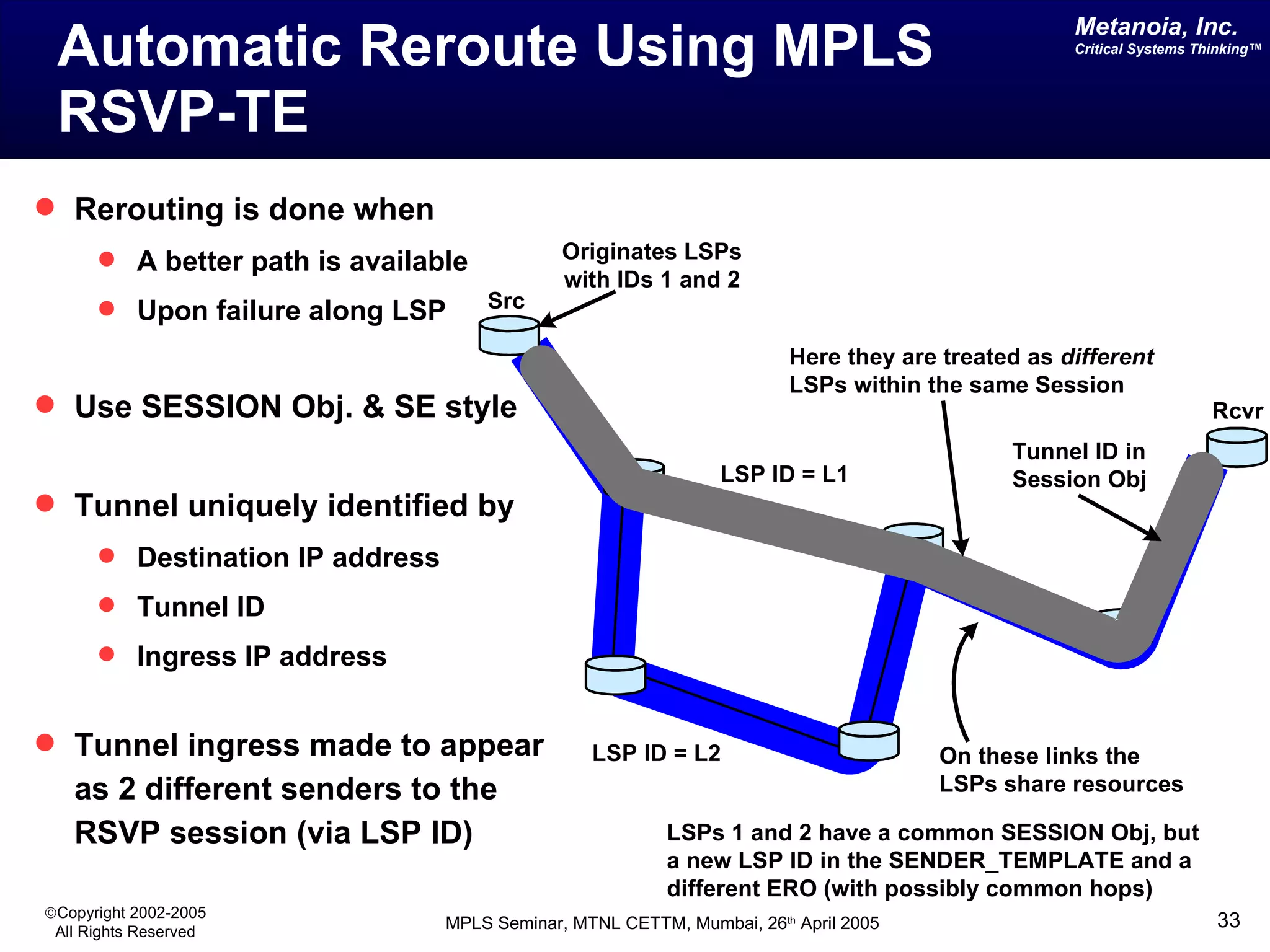

The document discusses Multi-Protocol Label Switching (MPLS), detailing its routing processes, advantages over conventional IP routing, and the decoupling of data and control planes. It explains how labels function in routing decisions, emphasizing their role in traffic engineering and network optimization. Additionally, it covers the methods for label distribution and the benefits of hierarchical routing and explicit routing in MPLS networks.


![MPLS L3 VPN Tutorial, by Nurul Islam Roman [APNIC 38]](https://cdn.slidesharecdn.com/ss_thumbnails/mplsl3vpnapnic381410820509-140915192004-phpapp02-thumbnail.jpg?width=640&height=640&fit=bounds)