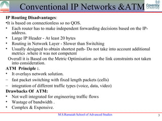
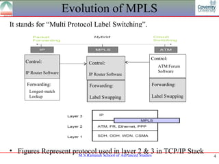
Presentation
          MPLS FOR TRAFFIC MANAGEMENT


                             S.T.RAJAN
                              CJB0912010, FT12
                     M. Sc. (Engg.) in Computer Science &
                                  Networking


Module Leader : Narasimha Murthy K.R


                          M.S.Ramaiah School of Advanced Studies   1
Session Topics
•   Convention IP Datagram & ATM
•   MPLS by Definition
•   Traffic Management
•   Terminology & Components
•   Primary Protocols for Qos & Cos
•   Working Mechanism
•   Implementation
•   Deployment Strategy
•   Summary


                      M.S.Ramaiah School of Advanced Studies   2
Conventional IP Networks &ATM
IP Routing Disadvantages:
•It is based on connectionless so no QOS.
• Each router has to make independent forwarding decisions based on the IP-
     address.
• Large IP Header - At least 20 bytes
• Routing in Network Layer - Slower than Switching
• Usually designed to obtain shortest path- Do not take into account additional
     metrics .where it was not competent
 Overall it is Based on the Metric Optimisation .so the link constraints not taken
     into consideration.
ATM Principle :.
• It overlays network solution.
– fast packet switching with fixed length packets (cells)
– integration of different traffic types (voice, data, video)
Drawbacks Of ATM:
• Not well integrated for engineering traffic flows
• Wastage of bandwidth .
• Complex & Expensive.
                             M.S.Ramaiah School of Advanced Studies                  3
Evolution of MPLS
It stands for “Multi Protocol Label Switching”.


                                                   Control:
     Control:                 Control:
                                                      ATM Forum
     IP Router Software                               Software
                              IP Router Software

     Forwarding:              Forwarding:          Forwarding:
       Longest-match
       Lookup                 Label Swapping       Label Swapping


• Figures Represent protocol used in layer 2 & 3 in TCP/IP Stack
                      M.S.Ramaiah School of Advanced Studies        4
Need for MPLS
MPLS Functions
•Uses Control-driven model.
•MPLS simplifies forwarding function by taking a totally different
approach by introducing a connection oriented mechanism inside the
connectionless IP networks
•Initially Designed for Enhancing Look up Speed for Routers but
essentially used for traffic engineering.
• IETF creates MPLS working group to create unified standard (Frame
Relay, PPP, SONET), not just ATM.
MPLS Characteristics
    – Mechanisms to manage traffic flows of various granularities (Flow
       Management) by using single forwarding algorithm .
    – Is independent of Layer-2 and Layer-3 protocols
    – Maps IP-addresses to fixed length labels
    – Interfaces to existing routing protocols (RSVP, OSPF)&futuristic
                         M.S.Ramaiah School of Advanced Studies       5
MPLS-TE Example
• Buses run with Route Number which is indication of route from
  start point .
• Similarly in MPLS each LSR will label the packets with the route
  label or swaps label and sends to the end Router
• Traffic management is done by signaling protocol with dedicated
  path called Trunk Tunneling .

                                           LSP


                                              Trunk Tunneling

                            Router B                            Router B


                      M.S.Ramaiah School of Advanced Studies               6
Need For Traffic Management
Traffic Management
•The task of mapping traffic flows onto an existing physical
topology to facilitate efficient and reliable network operations
• traffic oriented e.g. minimization of packet loss
•resource oriented - optimization of resource utilization e.g.
efficient management of bandwidth
Performance Objective
  Minimizing congestion is a major traffic and resource oriented
  performance objective
  Congestion manifest under two scenarios
      -network resources are insufficient or inadequate can be solved
      by capacity expansion or classical congestion control
      techniques
      -traffic streams are inefficiently mapped onto available
      resources can be reduced by adopting load balancing policies
                          M.S.Ramaiah School of Advanced Studies        7
Advantages of TM & Working
• Variously divisible traffic aggregation and disaggregation
  Maneuvering load distribution
• Stand-by secondary paths and precomputed detouring paths
  Strongly unified measurement and control for each “traffic-
  engineered path”
    Explanation :If network core runs conventional longest-match IP forwarding:
       –Data from Host A and B follow path 1 since it is the shortest-path
       computed.
       –With MPLS, network administrator could split traffic:
           •Host A traffic over path 1 & Host B traffic over path 2


                               M.S.Ramaiah School of Advanced Studies             8
Terminology
• FEC (Forwarding Equivalence Class)-Group of packets sharing
  the same type of transport.
• LSR (Label Switched Router)-Swaps labels on packets in core of
  network.
• LER (Label Edge Router)-Attach Labels to packets based on a
  FEC.
• LSP (Label Switch Path)-Path through network based on a FEC
  (simplex in nature). The “traffic-engineered path”
• LIB (Label Information Base)- MPLS equivalent to IP routing
  table, contains FEC-to-Label bindings
• Traffic Trunk (TT)
   -Traffic Trunk - aggregation of traffic flows of the same class
   which are placed inside a Label Switched Path
   -forwarded through a common path with common TE
   requirements characterized by its ingress and egress

                       M.S.Ramaiah School of Advanced Studies        9
Positions In MPLS
LER (Label Edge Router ) or Penultimate Router
LSR (Label Switch Router) or Transit Router
LSP:Label Switch Path
Mumbai is Ingress Router & Kolkata is Egress Router


 Mumbai                                                         Kolkata


            Pune      Secunderbad Vijayawada Bhuvaneshwar


                       M.S.Ramaiah School of Advanced Studies             10
LSP & Graphs
MPLS provides two options to set up an LSP
   • Hop-by-hop routing
     -Each LSR independently selects the next hop for a given
     FEC. LSRs support any available routing protocols (OSPF,
     ATM …).
   • Explicit routing
     -Is similar to source routing. The ingress LSR specifies the
     list of nodes through which the packet traverses.
The LSP setup for an FEC is unidirectional. The return traffic
must take another LSP!.Two types Static or dynamic.
Induced MPLS Graph
•analogous to a virtual topology in an overlay model
•logically mapped onto the physical network through the selections
o LSPs for traffic trunk
•comprises a set of LSRs which act as nodes of the graph and a set
of LSPs which provide logical point to point connectivity between
LSRs and thus act as edges of the graph Advanced Studies
                           M.S.Ramaiah School of                     11
Components MPLS-TE
• Packet Forwarding Component
   MPLS, label switching itself
• Information Distribution Component
   IGP (OSPF/IS-IS) extension
• Path Selection Component
   Constrained Shortest Path First (CSPF) algorithm or BGP
• Signaling Component
   LDP, CR-LDP, and RSVP-TE
   -In MPLS, traffic engineering is inherently provided using
   explicitly routed paths.
• The LSPs are created independently, specifying different paths
  that are based on user-defined policies. However, this may
  require extensive operator intervention.
• RSVP-TE and LDP are two possible approaches to supply
  dynamic traffic engineering and QoS in MPLS.
                        M.S.Ramaiah School of Advanced Studies     12
Dynamic LSP using RSVP
• Dynamic LSP Created without user intervention
• User control used by two protocol RSVP or LDP
RSVP (Resource Reservation Protocol)
•   Signaling Protocol designed by IETF
•   Application to request & reserves resources hop by hop
•   Request bandwidth and traffic conditions on a defined path.
•   Using “Path” message from source to destination
•   Reply message “Resv” From destination to source by updating “softstate”which is
    database for reservation .
•    Establishes the LSP.
•   LSP is operation as long as soft state
•   QOS and COS
•   The generic protocol is extension of MPLS implementation            R8
                                             R3                        R4
                      R2
Setup: Path (R2->R6->R7->R4)                                                R5
                                                                   Pop
Labels Established on Resv    R1           R6                 R7
message
                              M.S.Ramaiah School of Advanced Studies                  13
                                              22
LDP
Label Distribution Protocol designed specifically for MPLS
Four message classes
1. Discovery-Announce and
   maintain presence of an
   LSR.
2. Session-establish, maintain,
   terminate sessions b/w LDP
   peers.
3. Advertisement-create,
   change, delete label
   mappings.
4. Notification-advisory and
   error info.                       •Discovery: Runs over UDP
Multicast’s “Hello”                  •All others run over TCP
message is by LSR
                       M.S.Ramaiah School of Advanced Studies    14
CBR-LDP
   • Enables a demand driven, resource reservation aware, routing
     paradigm to co-exist with current topology driven protocols
      uses the following inputs
       traffic trunk attributes
       resource attributes
       other topology state information
   • Basic features
       prune the resources that do not meet the requirements of the
       traffic trunk attribute
       run a shortest path algorithm on the residual graph
Advantages of traffic trunks
•No. of trunks dependent only on the topology
•Forwarding table does not grow with the traffic
•Rerouting RSVP, CR-LDP, or IGP

                         M.S.Ramaiah School of Advanced Studies       15
Working Mechanism -TE
Steps For TE Establishment
• LSP Tunnels which are Signaled to RSVP which are unidirectional
•Link State IGP for global flooding of resource Information & automatic
routing of traffic .
•MPLS traffic engineering module for path calculation which path to be
used LSP tunnel.
•Link Management Module link admission and book keeping of resource
information to be flooded
•Label Switching Forwarding based on Resource based Routing
Algorithm
Mapping into Tunnel
•IGP uses Dijkstra's shortest path first (SPF) algorithm.
    Routing Tables are Derived from Shortest Path Tree.
•Another Algorithm calculates explicit route from one or more nodes
based on LSP and TE Tunnels
                         M.S.Ramaiah School of Advanced Studies      16
SFP Computation
Determination of first Hop Information
•When Path is found for new node it moves new node from tentative list
to path lists
•Based on TE Tunnel the tail end is First Hop Information updated
•Without TE Tunnel the uses First Hop Information from adjacent of
just connected node.
•When both Cases fail ,it copies the information from parent node to new
node.
Advantages
If there is more than one TE tunnel to different intermediate nodes on the
path to destination
node X, traffic flows over the TE tunnel whose tailend node is closest to
node X.


                          M.S.Ramaiah School of Advanced Studies        17
TE-Tunneling Mesh Network
         R-B           R-C

R-A


         R-D          R-E
Assume
Tunneling
present from A
to D and Same
cost Network.
Then SFP
implements to     The diagram shows Mesh Topology with dedicated
do load sharing   trunks

                       M.S.Ramaiah School of Advanced Studies      18
Signaling Protocols
•Implicit routing- labels are set-up and torn-down (like 
telephone calls), also known as hard state.
•Explicit routing- allows for better traffic engineering, traffic 
tunnels are created based on overall view of topology. More 
dynamic. 
                        Protocol         Routing             Traffic engineering
                           LDP            Implicit                  NO
                           BGP            Implicit                  NO
                           IS-IS          Implicit                  NO
                           CR-LPD         Explicit                  YES
                           RSVP-TE        Explicit                  YES
                           OSPF-
                                          Explicit                  YES
                           TE


                        M.S.Ramaiah School of Advanced Studies                     19
Implementation Consideration
 Management Interface


           Constraint Based                         Conventional
MPLS
           Routing Process                          IGP Process


  Resource Attribute                      Link State
  Availability Database                   Database


               M.S.Ramaiah School of Advanced Studies              20
Deployment Strategy-1
Congestion Free Network :
   1) Configure your IGP, RSVP
   2) Configure TE tunnels around congested links
        - one IGP tunnel, one or more explicit-path tunnels.
   3) Turn up tunnels one at a time via ‘autoroute announce’
          4) Add BW requirements to tunnels
        Tunnel BW ratio is important.
   Link Protection:
Step1: link failure detection
    O(depends on L2/L1)
Step2: IGP reaction (ISIS case)
    Either via Step1 or via IGP hello expiration (30s by default for
   ISIS) .5s (default) must occur by default before the generation of
   a new LSP
Step3: RSVP signalization

                          M.S.Ramaiah School of Advanced Studies        21
Deployment Strategy-2
Step4: Either stepA or stepB alarms the head-end
Step35: Re-optimization
    dijkstra computation: O(0.5)ms per node (rule of thumb)
    RSVP signalisation time to install re-routed tunnel
⇒convergence in the order of several seconds (at least).
⇒This includes fast switch over into secondary TE tunnel Path.
            Backup Tunnel to the next-hop of the
                       LSPs next-hopR3           R4


                 R2


       R1                                                          R5


                                                              R7
                  R6


                         M.S.Ramaiah School of Advanced Studies         22
MPLS-TE Deployment Issues
MPLS is proposed as a standard TE solution by IETF, BUT
      • Vendor Interoperability problem
      • Limitation in online path calculation
      • Problems on Traffic Trunks
      • Measurement and Control Issues


                        M.S.Ramaiah School of Advanced Studies   23
Summary
Based On MPLS
•Improves packet-forwarding performance in the network
•Supports QoS and CoS for service differentiation
•Supports network scalability
•Integrates IP and ATM in the network
•Builds interoperable networks
Based on MPLS TE:
•MPLS supports tunneling, which breaks the transparency paradigm.
•MPLS supports sessions, it breaks the datagram model.
•TE Done by SFP based on different Protocols.
•Higher return on network backbone infrastructure investment.
•Reduction in operating costs
•To increase the resource utilization
     MPLS Traffic Engineering
•To speed up convergence upon link or node failure
     MPLS TE and Link/Node protection
•To ease capacity planning -Aggregate Admission Control
                       M.S.Ramaiah School of Advanced Studies       24
References

•    Sreekanth P V, Digital Transmission Hierarchies, Universities
     Press ,2010,p209-225.
•    Ramaswami .R and Sivarajan. K. N. , Optical Networks: A
     Practical Perspective ,Morgan Kaufmann Publishers, 2nd .
•   Cisco IOS Release 11.3 Network Protocols Configuration Guide,
    Part 1, “Multiple Label Switching Traffic” chapter.


                     M.S.Ramaiah School of Advanced Studies          25
Thank You


M.S.Ramaiah School of Advanced Studies   26

S.t rajan cjb0912010 ft12

  • 1.
    Presentation MPLS FOR TRAFFIC MANAGEMENT S.T.RAJAN CJB0912010, FT12 M. Sc. (Engg.) in Computer Science & Networking Module Leader : Narasimha Murthy K.R M.S.Ramaiah School of Advanced Studies 1
  • 2.
    Session Topics • Convention IP Datagram & ATM • MPLS by Definition • Traffic Management • Terminology & Components • Primary Protocols for Qos & Cos • Working Mechanism • Implementation • Deployment Strategy • Summary M.S.Ramaiah School of Advanced Studies 2
  • 3.
    Conventional IP Networks&ATM IP Routing Disadvantages: •It is based on connectionless so no QOS. • Each router has to make independent forwarding decisions based on the IP- address. • Large IP Header - At least 20 bytes • Routing in Network Layer - Slower than Switching • Usually designed to obtain shortest path- Do not take into account additional metrics .where it was not competent Overall it is Based on the Metric Optimisation .so the link constraints not taken into consideration. ATM Principle :. • It overlays network solution. – fast packet switching with fixed length packets (cells) – integration of different traffic types (voice, data, video) Drawbacks Of ATM: • Not well integrated for engineering traffic flows • Wastage of bandwidth . • Complex & Expensive. M.S.Ramaiah School of Advanced Studies 3
  • 4.
    Evolution of MPLS Itstands for “Multi Protocol Label Switching”. Control: Control: Control: ATM Forum IP Router Software Software IP Router Software Forwarding: Forwarding: Forwarding: Longest-match Lookup Label Swapping Label Swapping • Figures Represent protocol used in layer 2 & 3 in TCP/IP Stack M.S.Ramaiah School of Advanced Studies 4
  • 5.
    Need for MPLS MPLSFunctions •Uses Control-driven model. •MPLS simplifies forwarding function by taking a totally different approach by introducing a connection oriented mechanism inside the connectionless IP networks •Initially Designed for Enhancing Look up Speed for Routers but essentially used for traffic engineering. • IETF creates MPLS working group to create unified standard (Frame Relay, PPP, SONET), not just ATM. MPLS Characteristics – Mechanisms to manage traffic flows of various granularities (Flow Management) by using single forwarding algorithm . – Is independent of Layer-2 and Layer-3 protocols – Maps IP-addresses to fixed length labels – Interfaces to existing routing protocols (RSVP, OSPF)&futuristic M.S.Ramaiah School of Advanced Studies 5
  • 6.
    MPLS-TE Example • Busesrun with Route Number which is indication of route from start point . • Similarly in MPLS each LSR will label the packets with the route label or swaps label and sends to the end Router • Traffic management is done by signaling protocol with dedicated path called Trunk Tunneling . LSP Trunk Tunneling Router B Router B M.S.Ramaiah School of Advanced Studies 6
  • 7.
    Need For TrafficManagement Traffic Management •The task of mapping traffic flows onto an existing physical topology to facilitate efficient and reliable network operations • traffic oriented e.g. minimization of packet loss •resource oriented - optimization of resource utilization e.g. efficient management of bandwidth Performance Objective Minimizing congestion is a major traffic and resource oriented performance objective Congestion manifest under two scenarios -network resources are insufficient or inadequate can be solved by capacity expansion or classical congestion control techniques -traffic streams are inefficiently mapped onto available resources can be reduced by adopting load balancing policies M.S.Ramaiah School of Advanced Studies 7
  • 8.
    Advantages of TM& Working • Variously divisible traffic aggregation and disaggregation Maneuvering load distribution • Stand-by secondary paths and precomputed detouring paths Strongly unified measurement and control for each “traffic- engineered path” Explanation :If network core runs conventional longest-match IP forwarding: –Data from Host A and B follow path 1 since it is the shortest-path computed. –With MPLS, network administrator could split traffic: •Host A traffic over path 1 & Host B traffic over path 2 M.S.Ramaiah School of Advanced Studies 8
  • 9.
    Terminology • FEC (ForwardingEquivalence Class)-Group of packets sharing the same type of transport. • LSR (Label Switched Router)-Swaps labels on packets in core of network. • LER (Label Edge Router)-Attach Labels to packets based on a FEC. • LSP (Label Switch Path)-Path through network based on a FEC (simplex in nature). The “traffic-engineered path” • LIB (Label Information Base)- MPLS equivalent to IP routing table, contains FEC-to-Label bindings • Traffic Trunk (TT) -Traffic Trunk - aggregation of traffic flows of the same class which are placed inside a Label Switched Path -forwarded through a common path with common TE requirements characterized by its ingress and egress M.S.Ramaiah School of Advanced Studies 9
  • 10.
    Positions In MPLS LER(Label Edge Router ) or Penultimate Router LSR (Label Switch Router) or Transit Router LSP:Label Switch Path Mumbai is Ingress Router & Kolkata is Egress Router Mumbai Kolkata Pune Secunderbad Vijayawada Bhuvaneshwar M.S.Ramaiah School of Advanced Studies 10
  • 11.
    LSP & Graphs MPLSprovides two options to set up an LSP • Hop-by-hop routing -Each LSR independently selects the next hop for a given FEC. LSRs support any available routing protocols (OSPF, ATM …). • Explicit routing -Is similar to source routing. The ingress LSR specifies the list of nodes through which the packet traverses. The LSP setup for an FEC is unidirectional. The return traffic must take another LSP!.Two types Static or dynamic. Induced MPLS Graph •analogous to a virtual topology in an overlay model •logically mapped onto the physical network through the selections o LSPs for traffic trunk •comprises a set of LSRs which act as nodes of the graph and a set of LSPs which provide logical point to point connectivity between LSRs and thus act as edges of the graph Advanced Studies M.S.Ramaiah School of 11
  • 12.
    Components MPLS-TE • PacketForwarding Component MPLS, label switching itself • Information Distribution Component IGP (OSPF/IS-IS) extension • Path Selection Component Constrained Shortest Path First (CSPF) algorithm or BGP • Signaling Component LDP, CR-LDP, and RSVP-TE -In MPLS, traffic engineering is inherently provided using explicitly routed paths. • The LSPs are created independently, specifying different paths that are based on user-defined policies. However, this may require extensive operator intervention. • RSVP-TE and LDP are two possible approaches to supply dynamic traffic engineering and QoS in MPLS. M.S.Ramaiah School of Advanced Studies 12
  • 13.
    Dynamic LSP usingRSVP • Dynamic LSP Created without user intervention • User control used by two protocol RSVP or LDP RSVP (Resource Reservation Protocol) • Signaling Protocol designed by IETF • Application to request & reserves resources hop by hop • Request bandwidth and traffic conditions on a defined path. • Using “Path” message from source to destination • Reply message “Resv” From destination to source by updating “softstate”which is database for reservation . • Establishes the LSP. • LSP is operation as long as soft state • QOS and COS • The generic protocol is extension of MPLS implementation R8 R3 R4 R2 Setup: Path (R2->R6->R7->R4) R5 Pop Labels Established on Resv R1 R6 R7 message M.S.Ramaiah School of Advanced Studies 13 22
  • 14.
    LDP Label Distribution Protocoldesigned specifically for MPLS Four message classes 1. Discovery-Announce and maintain presence of an LSR. 2. Session-establish, maintain, terminate sessions b/w LDP peers. 3. Advertisement-create, change, delete label mappings. 4. Notification-advisory and error info. •Discovery: Runs over UDP Multicast’s “Hello” •All others run over TCP message is by LSR M.S.Ramaiah School of Advanced Studies 14
  • 15.
    CBR-LDP • Enables a demand driven, resource reservation aware, routing paradigm to co-exist with current topology driven protocols uses the following inputs traffic trunk attributes resource attributes other topology state information • Basic features prune the resources that do not meet the requirements of the traffic trunk attribute run a shortest path algorithm on the residual graph Advantages of traffic trunks •No. of trunks dependent only on the topology •Forwarding table does not grow with the traffic •Rerouting RSVP, CR-LDP, or IGP M.S.Ramaiah School of Advanced Studies 15
  • 16.
    Working Mechanism -TE StepsFor TE Establishment • LSP Tunnels which are Signaled to RSVP which are unidirectional •Link State IGP for global flooding of resource Information & automatic routing of traffic . •MPLS traffic engineering module for path calculation which path to be used LSP tunnel. •Link Management Module link admission and book keeping of resource information to be flooded •Label Switching Forwarding based on Resource based Routing Algorithm Mapping into Tunnel •IGP uses Dijkstra's shortest path first (SPF) algorithm. Routing Tables are Derived from Shortest Path Tree. •Another Algorithm calculates explicit route from one or more nodes based on LSP and TE Tunnels M.S.Ramaiah School of Advanced Studies 16
  • 17.
    SFP Computation Determination offirst Hop Information •When Path is found for new node it moves new node from tentative list to path lists •Based on TE Tunnel the tail end is First Hop Information updated •Without TE Tunnel the uses First Hop Information from adjacent of just connected node. •When both Cases fail ,it copies the information from parent node to new node. Advantages If there is more than one TE tunnel to different intermediate nodes on the path to destination node X, traffic flows over the TE tunnel whose tailend node is closest to node X. M.S.Ramaiah School of Advanced Studies 17
  • 18.
    TE-Tunneling Mesh Network R-B R-C R-A R-D R-E Assume Tunneling present from A to D and Same cost Network. Then SFP implements to The diagram shows Mesh Topology with dedicated do load sharing trunks M.S.Ramaiah School of Advanced Studies 18
  • 19.
    Signaling Protocols •Implicit routing- labels are set-up and torn-down (like  telephone calls), also known as hard state. •Explicit routing- allows for better traffic engineering, traffic  tunnels are created based on overall view of topology. More  dynamic.  Protocol Routing Traffic engineering      LDP Implicit NO      BGP Implicit NO      IS-IS Implicit NO      CR-LPD Explicit YES      RSVP-TE Explicit YES      OSPF- Explicit YES TE M.S.Ramaiah School of Advanced Studies 19
  • 20.
    Implementation Consideration ManagementInterface Constraint Based Conventional MPLS Routing Process IGP Process Resource Attribute Link State Availability Database Database M.S.Ramaiah School of Advanced Studies 20
  • 21.
    Deployment Strategy-1 Congestion FreeNetwork : 1) Configure your IGP, RSVP 2) Configure TE tunnels around congested links - one IGP tunnel, one or more explicit-path tunnels. 3) Turn up tunnels one at a time via ‘autoroute announce’ 4) Add BW requirements to tunnels Tunnel BW ratio is important. Link Protection: Step1: link failure detection O(depends on L2/L1) Step2: IGP reaction (ISIS case) Either via Step1 or via IGP hello expiration (30s by default for ISIS) .5s (default) must occur by default before the generation of a new LSP Step3: RSVP signalization M.S.Ramaiah School of Advanced Studies 21
  • 22.
    Deployment Strategy-2 Step4: EitherstepA or stepB alarms the head-end Step35: Re-optimization dijkstra computation: O(0.5)ms per node (rule of thumb) RSVP signalisation time to install re-routed tunnel ⇒convergence in the order of several seconds (at least). ⇒This includes fast switch over into secondary TE tunnel Path. Backup Tunnel to the next-hop of the LSPs next-hopR3 R4 R2 R1 R5 R7 R6 M.S.Ramaiah School of Advanced Studies 22
  • 23.
    MPLS-TE Deployment Issues MPLSis proposed as a standard TE solution by IETF, BUT • Vendor Interoperability problem • Limitation in online path calculation • Problems on Traffic Trunks • Measurement and Control Issues M.S.Ramaiah School of Advanced Studies 23
  • 24.
    Summary Based On MPLS •Improvespacket-forwarding performance in the network •Supports QoS and CoS for service differentiation •Supports network scalability •Integrates IP and ATM in the network •Builds interoperable networks Based on MPLS TE: •MPLS supports tunneling, which breaks the transparency paradigm. •MPLS supports sessions, it breaks the datagram model. •TE Done by SFP based on different Protocols. •Higher return on network backbone infrastructure investment. •Reduction in operating costs •To increase the resource utilization MPLS Traffic Engineering •To speed up convergence upon link or node failure MPLS TE and Link/Node protection •To ease capacity planning -Aggregate Admission Control M.S.Ramaiah School of Advanced Studies 24
  • 25.
    References • Sreekanth P V, Digital Transmission Hierarchies, Universities Press ,2010,p209-225. • Ramaswami .R and Sivarajan. K. N. , Optical Networks: A Practical Perspective ,Morgan Kaufmann Publishers, 2nd . • Cisco IOS Release 11.3 Network Protocols Configuration Guide, Part 1, “Multiple Label Switching Traffic” chapter. M.S.Ramaiah School of Advanced Studies 25
  • 26.
    Thank You M.S.Ramaiah Schoolof Advanced Studies 26