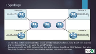
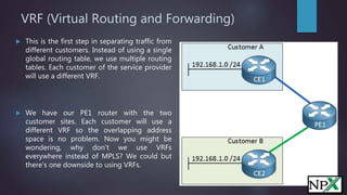
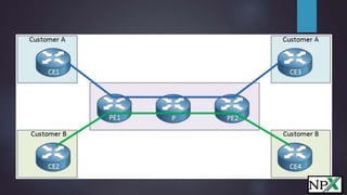
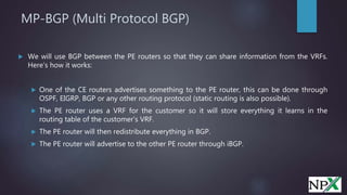
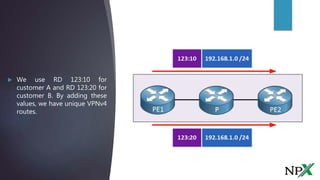
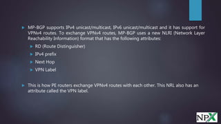
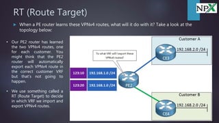
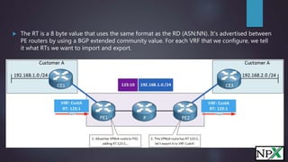
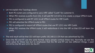
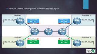
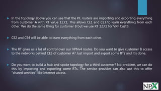
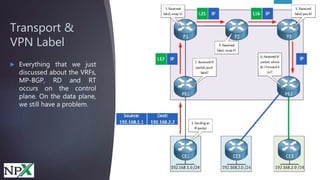
MPLS Layer 3 VPN Explained
WWW.NETPROTOCOLXPERT.IN
 Layer 3: the service provider will participate in routing with the customer.
The customer will run OSPF, EIGRP, BGP or any other routing protocol with
the service provider, these routes can be shared with other sites of the
customer.
 VPN: routing information from one customer is completely separated from
other customers and tunnelled over the service provider MPLS network.
Topology
• we have two customers connected to a service provider network. Customer A and B each have two sites
and you can see that they are using the same IP ranges.
• Customer A might use OSPF between their sites and customer B could use EIGRP between their sites.
Everything from these customers is completely separated by the service provider.
VRF (Virtual Routing and Forwarding)
 This is the first step in separating traffic from
different customers. Instead of using a single
global routing table, we use multiple routing
tables. Each customer of the service provider
will use a different VRF.
 We have our PE1 router with the two
customer sites. Each customer will use a
different VRF so the overlapping address
space is no problem. Now you might be
wondering, why don’t we use VRFs
everywhere instead of MPLS? We could but
there’s one downside to using VRFs.
 The problem with VRFs is that you have to create them everywhere. When our goal is to have
connectivity between CE1 and CE3 then we will have to add a VRF on the PE1, P and PE2 router.
Also, all the service provider routes will have to participate with routing. For example, when
customer A wants to run OSPF between their two sites then it means that we have to configure
OSPF on the PE1, P and PE2 router of the service provider for their VRF.
 When customer B wants to run EIGRP between their sites, we have to participate…we’ll have to
configure EIGRP on all service provider routers for the VRF of customer B.
 This is not a scalable solution so it’s not going to happen. Instead, we will configure the VRFs
only on the PE routers. The core of the service provider network (P router) will only do switching
based on labels.
 To share information about VRFs between PE routers, we will use BGP.
MP-BGP (Multi Protocol BGP)
 We will use BGP between the PE routers so that they can share information from the VRFs.
Here’s how it works:
 One of the CE routers advertises something to the PE router, this can be done through
OSPF, EIGRP, BGP or any other routing protocol (static routing is also possible).
 The PE router uses a VRF for the customer so it will store everything it learns in the
routing table of the customer’s VRF.
 The PE router will then redistribute everything in BGP.
 The PE router will advertise to the other PE router through iBGP.
 There’s a couple of problems though. First of all, our two customers are using overlapping
address space. Let’s say that our PE1 router is advertising 192.168.1.0 /24 from customer A to
the PE2 router on the other side.
 The PE2 router will learn 192.168.1.0 /24 from the PE1 router but it has no clue to what
customer it will belong. There is no way to differentiate if something belongs to customer A or
B.
 What we need is something to make all prefixes that we learn unique.
RD (Route Distinguisher)
 we will use a RD (Route Distinguisher). We will add something to the prefix of the customer
so that it will become unique:
 The RD is a 8 byte (64 bit) field. You can use any value you want but typically we use the
ASN:NN format where ASN is the service provider’s AS number and NN is a number we pick
that identifies the site of the customer.
 The RD and the prefix combined is what we call a VPNv4 route. We now have a method to
differentiate between the different prefixes of our customers.
 We use RD 123:10 for
customer A and RD 123:20 for
customer B. By adding these
values, we have unique VPNv4
routes.
 MP-BGP supports IPv4 unicast/multicast, IPv6 unicast/multicast and it has support for
VPNv4 routes. To exchange VPNv4 routes, MP-BGP uses a new NLRI (Network Layer
Reachability Information) format that has the following attributes:
 RD (Route Distinguisher)
 IPv4 prefix
 Next Hop
 VPN Label
 This is how PE routers exchange VPNv4 routes with each other. This NRL also has an
attribute called the VPN label.
RT (Route Target)
 When a PE router learns these VPNv4 routes, what will it do with it? Take a look at the
topology below:
• Our PE2 router has learned
the two VPNv4 routes, one
for each customer. You
might think that the PE2
router will automatically
export each VPNv4 route in
the correct customer VRF
but that’s not going to
happen.
• We use something called a
RT (Route Target) to decide
in which VRF we import and
export VPNv4 routes.
 The RT is a 8 byte value that uses the same format as the RD (ASN:NN). It's advertised between
PE routers by using a BGP extended community value. For each VRF that we configure, we tell
it what RTs we want to import and export.
 Let me explain the Topology above:
 Both PE routers are configured to use a VRF called "CustA“ for customer A.
 When PE1 receives a prefix from CE1, it will add RD 123:10 to it to create a unique VPNv4 route.
 PE1 is configured to add RT 123:1 to all VPNv4 routes for VRF CustA.
 PE1 will advertise the VPNv4 route to PE2.
 PE2 is configured to export all VPNv4 routes that use RT 123:1 into VRF CustA.
 When PE2 receives the VPNv4 route, it will redistribute it into the VRF so that CE3 will learn the
prefix.
 The end result will be that CE3 will learn prefix 192.168.1.0 /24 that was advertised by CE1.
 Since the RD and RT use the same format, many people confuse these two. Normally we use the
same value for these two but to emphasize that the RD and RT are two different things, I used
123:10 for the RD and 123:1 for the RT.
 Now let see the topology with our two customers again:
 In the topology above you can see that the PE routers are importing and exporting everything
from customer A with RT value 123:1. This allows CE1 and CE3 to learn everything from each
other. We do the same thing for customer B but we use RT 123:2 for VRF CustB.
 CE2 and CE4 will be able to learn everything from each other.
 The RT gives us a lot of control over our VPNv4 routes. Do you want to give customer B access
to the networks behind CE3 of customer A? Just import and export some RTs and it's done.
 Do you want to build a hub and spoke topology for a third customer? No problem, we can do
this by importing and exporting some RTs. The service provider can also use this to offer
"shared services" like Internet access.
Transport &
VPN Label
 Everything that we just
discussed about the VRFs,
MP-BGP, RD and RT
occurs on the control
plane. On the data plane,
we still have a problem.
 In the topology above I have added a couple of extra P routers so that we have a nice
example of how the routers in the service provider network forward traffic. In the example,
the CE1 router from the customer is sending an IP packet with source address 192.168.1.1
and destination 192.168.2.2 to the PE1 router.
 The PE1 router will add a transport label to the IP packet and our MPLS packet will be label
switched all the way to P3 which pops the label (penultimate hop popping) so that PE2
receives the IP packet.
 In the header of this IP packet, there's nothing that will help PE2 decide where to forward it
to.
 To fix this problem, we will add a second label to the IP packet called the VPN label Besides
the RT, the PE1 router will also advertise a VPN label to the PE2 router.
 The CE1 router sends an IP packet to the PE1 router.
 The PE1 router will first add a VPN label to the IP packet, in this example we'll pick number
21.
 The PE1 router also adds a transport label to it and it will be forwarded to the P1 router.
 The packet makes it to the P3 router, which pops the transport label.
 PE2 sees VPN label 21 and knows that this belongs to the RT of the VRF that connects to
CE3. It pops the label and forwards the IP packet to CE3.
Follow us @
 www.facebook.com/NetProtocolXpert
 www.instagram.com/netprotocol_xpert
 plus.google.com/collection/k8HMDB
 twitter.com/NPX_cisco
 www.linkedin.com/company/netprotocol-xpert
 netprotocolxpert.blogspot.in
 remote.com/netprotocolxpert
 www.netprotocolxpert.in

MPLS Layer 3 VPN

  • 1.
    MPLS Layer 3VPN Explained WWW.NETPROTOCOLXPERT.IN
  • 2.
     Layer 3:the service provider will participate in routing with the customer. The customer will run OSPF, EIGRP, BGP or any other routing protocol with the service provider, these routes can be shared with other sites of the customer.  VPN: routing information from one customer is completely separated from other customers and tunnelled over the service provider MPLS network.
  • 3.
    Topology • we havetwo customers connected to a service provider network. Customer A and B each have two sites and you can see that they are using the same IP ranges. • Customer A might use OSPF between their sites and customer B could use EIGRP between their sites. Everything from these customers is completely separated by the service provider.
  • 4.
    VRF (Virtual Routingand Forwarding)  This is the first step in separating traffic from different customers. Instead of using a single global routing table, we use multiple routing tables. Each customer of the service provider will use a different VRF.  We have our PE1 router with the two customer sites. Each customer will use a different VRF so the overlapping address space is no problem. Now you might be wondering, why don’t we use VRFs everywhere instead of MPLS? We could but there’s one downside to using VRFs.
  • 6.
     The problemwith VRFs is that you have to create them everywhere. When our goal is to have connectivity between CE1 and CE3 then we will have to add a VRF on the PE1, P and PE2 router. Also, all the service provider routes will have to participate with routing. For example, when customer A wants to run OSPF between their two sites then it means that we have to configure OSPF on the PE1, P and PE2 router of the service provider for their VRF.  When customer B wants to run EIGRP between their sites, we have to participate…we’ll have to configure EIGRP on all service provider routers for the VRF of customer B.  This is not a scalable solution so it’s not going to happen. Instead, we will configure the VRFs only on the PE routers. The core of the service provider network (P router) will only do switching based on labels.  To share information about VRFs between PE routers, we will use BGP.
  • 7.
    MP-BGP (Multi ProtocolBGP)  We will use BGP between the PE routers so that they can share information from the VRFs. Here’s how it works:  One of the CE routers advertises something to the PE router, this can be done through OSPF, EIGRP, BGP or any other routing protocol (static routing is also possible).  The PE router uses a VRF for the customer so it will store everything it learns in the routing table of the customer’s VRF.  The PE router will then redistribute everything in BGP.  The PE router will advertise to the other PE router through iBGP.
  • 8.
     There’s acouple of problems though. First of all, our two customers are using overlapping address space. Let’s say that our PE1 router is advertising 192.168.1.0 /24 from customer A to the PE2 router on the other side.
  • 9.
     The PE2router will learn 192.168.1.0 /24 from the PE1 router but it has no clue to what customer it will belong. There is no way to differentiate if something belongs to customer A or B.  What we need is something to make all prefixes that we learn unique.
  • 10.
    RD (Route Distinguisher) we will use a RD (Route Distinguisher). We will add something to the prefix of the customer so that it will become unique:  The RD is a 8 byte (64 bit) field. You can use any value you want but typically we use the ASN:NN format where ASN is the service provider’s AS number and NN is a number we pick that identifies the site of the customer.  The RD and the prefix combined is what we call a VPNv4 route. We now have a method to differentiate between the different prefixes of our customers.
  • 11.
     We useRD 123:10 for customer A and RD 123:20 for customer B. By adding these values, we have unique VPNv4 routes.
  • 12.
     MP-BGP supportsIPv4 unicast/multicast, IPv6 unicast/multicast and it has support for VPNv4 routes. To exchange VPNv4 routes, MP-BGP uses a new NLRI (Network Layer Reachability Information) format that has the following attributes:  RD (Route Distinguisher)  IPv4 prefix  Next Hop  VPN Label  This is how PE routers exchange VPNv4 routes with each other. This NRL also has an attribute called the VPN label.
  • 13.
    RT (Route Target) When a PE router learns these VPNv4 routes, what will it do with it? Take a look at the topology below: • Our PE2 router has learned the two VPNv4 routes, one for each customer. You might think that the PE2 router will automatically export each VPNv4 route in the correct customer VRF but that’s not going to happen. • We use something called a RT (Route Target) to decide in which VRF we import and export VPNv4 routes.
  • 14.
     The RTis a 8 byte value that uses the same format as the RD (ASN:NN). It's advertised between PE routers by using a BGP extended community value. For each VRF that we configure, we tell it what RTs we want to import and export.
  • 15.
     Let meexplain the Topology above:  Both PE routers are configured to use a VRF called "CustA“ for customer A.  When PE1 receives a prefix from CE1, it will add RD 123:10 to it to create a unique VPNv4 route.  PE1 is configured to add RT 123:1 to all VPNv4 routes for VRF CustA.  PE1 will advertise the VPNv4 route to PE2.  PE2 is configured to export all VPNv4 routes that use RT 123:1 into VRF CustA.  When PE2 receives the VPNv4 route, it will redistribute it into the VRF so that CE3 will learn the prefix.  The end result will be that CE3 will learn prefix 192.168.1.0 /24 that was advertised by CE1.  Since the RD and RT use the same format, many people confuse these two. Normally we use the same value for these two but to emphasize that the RD and RT are two different things, I used 123:10 for the RD and 123:1 for the RT.
  • 16.
     Now letsee the topology with our two customers again:
  • 17.
     In thetopology above you can see that the PE routers are importing and exporting everything from customer A with RT value 123:1. This allows CE1 and CE3 to learn everything from each other. We do the same thing for customer B but we use RT 123:2 for VRF CustB.  CE2 and CE4 will be able to learn everything from each other.  The RT gives us a lot of control over our VPNv4 routes. Do you want to give customer B access to the networks behind CE3 of customer A? Just import and export some RTs and it's done.  Do you want to build a hub and spoke topology for a third customer? No problem, we can do this by importing and exporting some RTs. The service provider can also use this to offer "shared services" like Internet access.
  • 18.
    Transport & VPN Label Everything that we just discussed about the VRFs, MP-BGP, RD and RT occurs on the control plane. On the data plane, we still have a problem.
  • 19.
     In thetopology above I have added a couple of extra P routers so that we have a nice example of how the routers in the service provider network forward traffic. In the example, the CE1 router from the customer is sending an IP packet with source address 192.168.1.1 and destination 192.168.2.2 to the PE1 router.  The PE1 router will add a transport label to the IP packet and our MPLS packet will be label switched all the way to P3 which pops the label (penultimate hop popping) so that PE2 receives the IP packet.  In the header of this IP packet, there's nothing that will help PE2 decide where to forward it to.  To fix this problem, we will add a second label to the IP packet called the VPN label Besides the RT, the PE1 router will also advertise a VPN label to the PE2 router.
  • 21.
     The CE1router sends an IP packet to the PE1 router.  The PE1 router will first add a VPN label to the IP packet, in this example we'll pick number 21.  The PE1 router also adds a transport label to it and it will be forwarded to the P1 router.  The packet makes it to the P3 router, which pops the transport label.  PE2 sees VPN label 21 and knows that this belongs to the RT of the VRF that connects to CE3. It pops the label and forwards the IP packet to CE3.
  • 22.
    Follow us @ www.facebook.com/NetProtocolXpert  www.instagram.com/netprotocol_xpert  plus.google.com/collection/k8HMDB  twitter.com/NPX_cisco  www.linkedin.com/company/netprotocol-xpert  netprotocolxpert.blogspot.in  remote.com/netprotocolxpert  www.netprotocolxpert.in