Download as PDF, PPTX

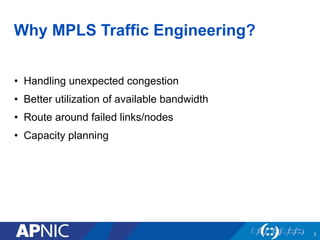
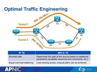
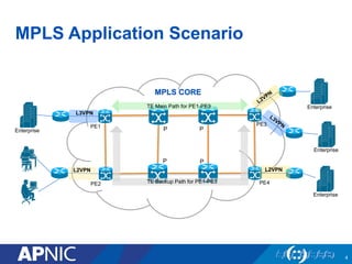
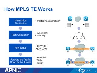
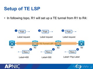
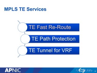
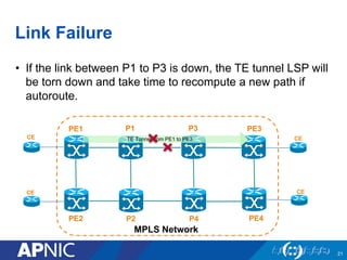
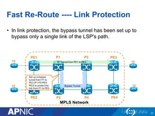
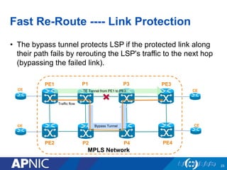
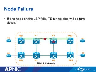

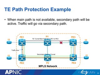

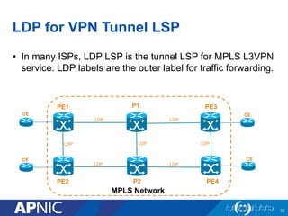
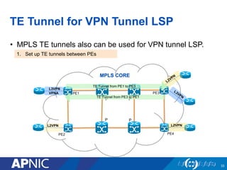
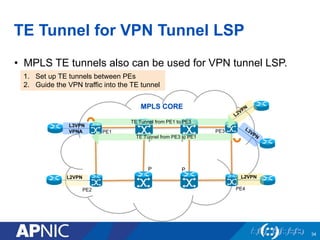


The document presents an overview of MPLS traffic engineering, focusing on its importance for managing congestion, optimizing bandwidth utilization, and providing robust routing strategies. It details the mechanisms involved in creating and managing MPLS tunnels, including dynamic and explicit path selection, fast reroute for link and node protection, and the application of path protection techniques. Additionally, it covers the use of MPLS for VPN services, ensuring traffic routing is efficient and reliable.