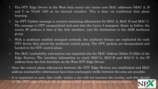
OTV is a technology that provides layer 2 extension capabilities between different data centers without using tunnels. It encapsulates layer 2 traffic with an IP header and transports it across an IP network. OTV devices called edge devices perform layer 2 learning and forwarding within a data center and encapsulation functions to extend layer 2 traffic across sites using IP addresses and multicast groups for control and data plane MAC address advertisement and traffic forwarding between sites.
CCNA DC ,CCNP DC ,CCIE DC ,CCIE DC RACK RENTALS ,CCIE DC LEARNING PPT ,CCIE DC ONLINE TRAINING.
UCS RACK RENTALS ,MDS RACK RENTALS ,NEXUS 7000 RACK RENALS
CCNA DC ,CCNP DC ,CCIE DC ,CCIE DC RACK RENTALS ,CCIE DC LEARNING PPT ,CCIE DC ONLINE TRAINING.
UCS RACK RENTALS ,MDS RACK RENTALS ,NEXUS 7000 RACK RENALS
1) Describe the three primary options for enabling inter-VLAN routing.
2) Configure legacy inter-VLAN routing.
3) Configure router-on-a-stick inter-VLAN routing.
4) Troubleshoot common inter-VLAN configuration issues.
5) Troubleshoot common IP addressing issues in an inter-VLAN-routed environment.
6) Configure inter-VLAN routing using Layer 3 switching.
7) Troubleshoot inter-VLAN routing in a Layer 3-switched environment.
EIGRP is a cisco proprietary, Advance distance vector, classless Interior gateway routing protocol.
Released in-1994.
It works on Network Layer of OSI Model.
It use the IP protocol no 88. (It doesn’t use TCP or UDP)
EIGRP AD – 90
Eigrp External routes AD – 170
EIGRP has a maximum hop-count of 224, though the default maximum hop-count is set to 100
Building DataCenter networks with VXLAN BGP-EVPNCisco Canada
The session specifically covers the requirements and approaches for deploying the Underlay, Overlay as well as the inter-Fabric connectivity of Data Center Networks or Fabrics. Within the VXLAN BGP-EVPN based Overlay, we focus on the insights like forwarding and control plane functions which are critical to the simplicity operation of the architecture in achieving scale, small failure domains and consistent configuration. To complete the overlay view on VXLAN BGP-EVPN, we are going to the insides of BGP and its EVPN address-familiy and extend to about how multiple DC Fabric can be interconnected within, either as stretched Fabrics or with true DCI. The session concludes with a brief overview of manageability functions, network orchestration capabilities and multi-tenancy details. This Advanced session is intended for network, design and operation engineers from Enterprises to Service Providers.
GLBP (Gateway Load Balancing Protocol) is a Cisco proprietary protocol that attempts to overcome the
limitations of existing redundant router protocols by adding basic load balancing functionality. GLBP is a
virtual gateway protocol similar to HSRP and VRRP.
However, unlike its little brothers, GLBP is capable of using multiple physical gateways at the same time.
As we know, a single HSRP or VRRP group represents one virtual gateway, with single virtual IP and MAC
addresses. Only one physical gateway in a standby/redundancy group is responsible for packet
forwarding, others remain inactive in standby/backup state.
VRRP (Virtual Router Redundancy Protocol) is a computer networking protocol that provides for
automatic assignment of available Internet Protocol (IP) routers to participating hosts. This increases the
availability and reliability of routing paths via automatic default gateway selections on an IP subnetwork.
The Virtual Router Redundancy Protocol (VRRP) eliminates the single point of failure inherent in the
static default routed environment. VRRP specifies an election protocol that dynamically assigns
responsibility for a virtual router (a VPN 3000 Series Concentrator cluster) to one of the VPN
Concentrators on a LAN. The VRRP VPN Concentrator that controls the IP address(es) associated with a
virtual router is called the Master, and forwards packets sent to those IP addresses.
VLAN Trunking Protocol (VTP) is a Cisco proprietary protocol that propagates the definition of Virtual
Local Area Networks (VLAN) on the whole local area network.[1] To do this, VTP carries VLAN
information to all the switches in a VTP domain. VTP advertisements can be sent over ISL, 802.1Q, IEEE
802.10 and LANE trunks. VTP is available on most of the Cisco Catalyst Family products.
CCNA DC ,CCNP DC ,CCIE DC ,CCIE DC RACK RENTALS ,CCIE DC LEARNING PPT ,CCIE DC ONLINE TRAINING.
UCS RACK RENTALS ,MDS RACK RENTALS ,NEXUS 7000 RACK RENALS
L3 and Multicasting PPT by NETWORKERS HOMEnetworkershome
CCNA DC ,CCNP DC ,CCIE DC ,CCIE DC RACK RENTALS ,CCIE DC LEARNING PPT ,CCIE DC ONLINE TRAINING.
UCS RACK RENTALS ,MDS RACK RENTALS ,NEXUS 7000 RACK RENALS
Highly Focussed on CCIE Learning .11 Full CCIE DC Racks for your CCIE Needs .Demo available for our Online Classes and Online CCIE DC Racks .Take Demo and Decide yourself .World Class Racks based in New Jersey ,USA and Bangalore India .Email rack@networkershome.com
Relatore: Alessandro Legnani, Cisco CCIE e IP Network Architect di IT Global Consulting Srl
Sintesi e sinergia perfetta di un nuovo protocollo di routing (e non solo) con il caro vecchio e robusto IPsec (senza le problematiche ike). Perché inventarsi l’ennesima forma di tunnelig per il data plane?
Quanto sopra è la chiave del successo della soluzione sdwan Cisco/Viptela che la rende enormemente scalabile e unica sul mercato.
This pdf is about the CAN communication protocol, which is vital for automobiles.A Brief Overview. The CAN bus protocol is defined by the ISO 11898-1 standard and can be summarized like this: The physical layer uses differential transmission on a twisted pair wire. A non-destructive bit-wise arbitration is used to control access to the bus. This is made with the help of Engineersgarage.
This presentations gives basic overview about networking and in depth insights about Openstack Neutron component.
Covers understanding on VLAN,VXLAN,Openstack vSwitch
Adhoc mobile wireless network enhancement based on cisco devicesIJCNCJournal
Adhoc wireless networks become one of the most researchable areas in the studying of routing protocols depending on the Open System Interconnection (OSI Model). This paper use Cisco devices as a reference to enhance the performance of the network. This enhancement will be due to high processing, reliability, average cost, power consumption and accessibility. The aim of this research not only to get the cost down, it also to choose a time to time device to process the data as rapid as it can. Using NAT, Access List and DHCP protocols defined in Cisco (Graphical Unit Interface) GUI of the (Command Line Interface) CLI, the task can be made.
Overview of the fundamental roles in Hydropower generation and the components involved in wider Electrical Engineering.
This paper presents the design and construction of hydroelectric dams from the hydrologist’s survey of the valley before construction, all aspects and involved disciplines, fluid dynamics, structural engineering, generation and mains frequency regulation to the very transmission of power through the network in the United Kingdom.
Author: Robbie Edward Sayers
Collaborators and co editors: Charlie Sims and Connor Healey.
(C) 2024 Robbie E. Sayers
Industrial Training at Shahjalal Fertilizer Company Limited (SFCL)MdTanvirMahtab2
This presentation is about the working procedure of Shahjalal Fertilizer Company Limited (SFCL). A Govt. owned Company of Bangladesh Chemical Industries Corporation under Ministry of Industries.
Student information management system project report ii.pdfKamal Acharya
Our project explains about the student management. This project mainly explains the various actions related to student details. This project shows some ease in adding, editing and deleting the student details. It also provides a less time consuming process for viewing, adding, editing and deleting the marks of the students.
Cosmetic shop management system project report.pdfKamal Acharya
Buying new cosmetic products is difficult. It can even be scary for those who have sensitive skin and are prone to skin trouble. The information needed to alleviate this problem is on the back of each product, but it's thought to interpret those ingredient lists unless you have a background in chemistry.
Instead of buying and hoping for the best, we can use data science to help us predict which products may be good fits for us. It includes various function programs to do the above mentioned tasks.
Data file handling has been effectively used in the program.
The automated cosmetic shop management system should deal with the automation of general workflow and administration process of the shop. The main processes of the system focus on customer's request where the system is able to search the most appropriate products and deliver it to the customers. It should help the employees to quickly identify the list of cosmetic product that have reached the minimum quantity and also keep a track of expired date for each cosmetic product. It should help the employees to find the rack number in which the product is placed.It is also Faster and more efficient way.
Immunizing Image Classifiers Against Localized Adversary Attacksgerogepatton
This paper addresses the vulnerability of deep learning models, particularly convolutional neural networks
(CNN)s, to adversarial attacks and presents a proactive training technique designed to counter them. We
introduce a novel volumization algorithm, which transforms 2D images into 3D volumetric representations.
When combined with 3D convolution and deep curriculum learning optimization (CLO), itsignificantly improves
the immunity of models against localized universal attacks by up to 40%. We evaluate our proposed approach
using contemporary CNN architectures and the modified Canadian Institute for Advanced Research (CIFAR-10
and CIFAR-100) and ImageNet Large Scale Visual Recognition Challenge (ILSVRC12) datasets, showcasing
accuracy improvements over previous techniques. The results indicate that the combination of the volumetric
input and curriculum learning holds significant promise for mitigating adversarial attacks without necessitating
adversary training.
CFD Simulation of By-pass Flow in a HRSG module by R&R Consult.pptxR&R Consult
CFD analysis is incredibly effective at solving mysteries and improving the performance of complex systems!
Here's a great example: At a large natural gas-fired power plant, where they use waste heat to generate steam and energy, they were puzzled that their boiler wasn't producing as much steam as expected.
R&R and Tetra Engineering Group Inc. were asked to solve the issue with reduced steam production.
An inspection had shown that a significant amount of hot flue gas was bypassing the boiler tubes, where the heat was supposed to be transferred.
R&R Consult conducted a CFD analysis, which revealed that 6.3% of the flue gas was bypassing the boiler tubes without transferring heat. The analysis also showed that the flue gas was instead being directed along the sides of the boiler and between the modules that were supposed to capture the heat. This was the cause of the reduced performance.
Based on our results, Tetra Engineering installed covering plates to reduce the bypass flow. This improved the boiler's performance and increased electricity production.
It is always satisfying when we can help solve complex challenges like this. Do your systems also need a check-up or optimization? Give us a call!
Work done in cooperation with James Malloy and David Moelling from Tetra Engineering.
More examples of our work https://www.r-r-consult.dk/en/cases-en/
2. • OTV(Overlay Transport Virtualization) is a technology that provide layer2
extension capabilities between different data centers.
• In its most simplest form OTV is a new DCI (Data Center Interconnect)
technology that routes MAC-based information by encapsulating traffic in
normal IP packets for transit.
3. OTV OVERVIEW
• Traditional L2VPN technologies, like EoMPLS and VPLS, rely heavily on
tunnels. Rather than creating stateful tunnels, OTV encapsulates layer2
traffic with an IP header and does not create any fixed tunnels.
• OTV only requires IP connectivity between remote data center sites, which
allows for the transport infrastructures to be layer2 based, layer3 based, or
even label switched. IP connectivity as the base requirement along some
additional connectivity requirements.
• OTV requires no changes to existing data centers to work, but it is
currently only supported on the Nexus 7000 series switches with M1-Series
linecards.
4. • A big enhancement OTV brings to the DCI realm, is its control plane functionality of
advertising MAC reachability information instead of relying on the traditional data plane
learning of MAC flooding. OTV refers to this concept as MAC routing, aka, MAC-in-IP
routing. The MAC-in-IP routing is done by encapsulating an Ethernet frame in an IP packet
before forwarded across the transport IP network. The action of encapsulating the traffic
between the OTV devices, creates what is called an overlay between the data center sites.
Think of an overlay as a logical multipoint bridged network between the sites.
• OTV is deployed on devices at the edge of the data center sites, called OTV Edge Devices.
These Edge Devices perform typical layer-2 learning and forwarding functions on their site
facing interfaces (the Internal Interfaces) and perform IP-based virtualization functions on
their core facing interface (the Join Interface) for traffic that is destined via the logical
bridge interface between DC sites (the Overlay Interface).
• Each Edge Device must have an IP address which is significant in the core/provider network
for reachability, but is not required to have any IGP relationship with the core. This allows
OTV to be inserted into any type of network in a much simpler fashion.
6. OTV Edge Device
• Is a device (Nexus 7000 or Nexus 7000 VDC) that sits at the edge of a data center,
performing all the OTV functions, with the purpose to connect to other data centers.
• The OTV edge device is connected to the layer2 DC domain as well as the IP transport
network.
• With NX-OS 5.1 a maximum of two OTV edge devices can be deployed on a site to allow
for redundancy.
Internal Interfaces
• Are the layer2 interfaces on the OTV Edge Device configured as a trunk or an access
port.
• Internal interfaces take part in the STP domain and learns MAC addresses as per
normal.
7. Join Interface
• Is a layer3 interface on the OTV Edge Device that connects to the IP transport network.
• This interface is used as the source for OTV encapsulated traffic that is sent to remote OTV
Edge Devices.
• With NX-OS 5.1 this must be a physical interface or layer3 port channel. Loopback interfaces
are not supported in the current implementations.
• A single Join interface can be defined and associated with a given OTV overlay.
• Multiple overlays can also share the same Join interface.
Overlay Interface
• Is a logical multi-access and multicast-capable interface where all the OTV configuration are
explicitly defined by a user.
• The overlay interface acts as a logical bridge interface between DC sites to show which layer2
frames should be dynamically encapsulated by OTV before forwarded out the join interface.
8. OTV Control-Group
• Is the multicast group used by OTV speaker in an overlay network.
• A unique multicast address is required for each overlay group.
OTV Data-Group
• Used to encapsulate any layer2 multicast traffic that is extended across the overlay
• Extended-VLANs
• Are the VLANs that are explicitly allowed to be extended across the overlay between sites.
• If not explicitly allowed, the MAC addresses from a VLAN will not be advertised across the overlay.
Site-VLAN
• Is the VLAN used for communication between local OTV edge devices within a site.
• Is used to facilitate the role election of the AED (Authoritative Edge Devices).
• The Site Vlan must be exist and be active (defined or use default configuration).
9. OTV OPERATION
• As mentioned already OTV relies on the control plane to advertise MAC reachability information. The
underlying routing-protocol used in the control-plane is IS-IS (Intermediate System to Intermediate
System). IS-IS hellos and LSPs are encapsulated in the OTV IP multicast header. The OTV IS-IS
packets use a distinct Layer-2 multicast destination address. Therefore, OTV IS-IS packets do not
conflict with IS-IS packets used for other technologies
• The use of IS-IS is obvious to two reasons.
1. Firstly IS-IS does not use IP to carry routing information messages, it uses CLNS. Thus IS-IS is
neutral regarding the type of network addresses for which it can route traffic, making it ideal to
route MAC reachability information.
2. Secondly through the use of TLVs. A TLV (Type, Length, Value) is an encoding format used to add
optional information to data communication protocols like IS-IS. This is how IS-IS could easily be
extended to carry the new information fields
• Do you need to understand IS-IS to understand OTV? Do you need to know how the engine of a car
works in order to drive it? No, but its best to have at least a base understanding how it all fits together.
10. • Before any MAC reachability information can be exchanged, all OTV Edge Devices
must become “adjacent”.
• This is possible by using the specified OTV Control-Group across the transport
infrastructure to exchange the control protocol messages and advertise the MAC
reachability information.
• Additional documentation indicates that unicast transport support will be possible in
future Cisco software releases (post NX-OS 5.1), by using a concept known as an
“Adjacency Server”.
• For now lets focus on using multicast in the transport infrastructure. All OTV Edge
Devices should be configured to join a specific ASM (Any Source Multicast) group
where they simultaneously play the role of receiver and source. This is a multicast
host functionality.
12. 1. Each OTV Edge Device sends an IGMP report to join the specific ASM group used to
carry control protocol exchanges. The Edge Devices join the group as hosts. This is IGMP,
not PIM.
2. OTV Hello packets are generated to all other OTV Edge Devices, to communicate the
local Edge Devices existence and to trigger the establishment of control plane
adjacencies.
3. The OTV Hello packets are sent across the logical overlay to the remote device. This
action implies that the original frames are OTV encapsulated by adding an external IP
header. The source IP address is that of the Join interface, and the destination is the
ASM multicast group as specified for the control traffic.
4. With a multicast enabled transport network, the multicast frames are replicated for each
OTV device that joined the multicast control group.
5. The receiving OTV Edge Devices strips of the encapsulated IP header. Before it is passed
to the control plane for processing.
6. Once the OTV Edge Devices have discovered each other, they are ready to exchange MAC
address reachability information, which follows a very similar process.
14. 1. The OTV Edge Device in the West data center site learns new MAC addresses (MAC A, B
and C on VLAN 100) on its internal interface. This is done via traditional data plane
learning.
2. An OTV Update message is created containing information for MAC A, MAC B and MAC C.
The message is OTV encapsulated and sent into the Layer 3 transport. Same as before, the
source IP address is that of the Join interface, and the destination is the ASM multicast
group.
3. With a multicast enabled transport network, the multicast frames are replicated for each
OTV device that joined the multicast control group. The OTV packets are decapsulated and
handed to the OTV control plane.
4. The MAC reachability information are imported into the MAC Address Tables (CAMs) of the
Edge Devices. The interface information to reach MAC-A, MAC-B and MAC-C is the IP
address from the Join Interface on the West OTV Edge Device.
• Once the control plane adjacencies between the OTV Edge Devices are established and MAC
address reachability information have been exchanged, traffic between the sites are possible.
• It is important to note, that traffic within a site will not traverse the overlay, and why should
it? The OTV edge will have the destination MAC pointing towards a local interface.
16. 1. A layer2 frame is destined to a MAC address learned via the overlay, since the next-hop
interface is across the overlay.
2. The original layer2 frame is OTV encapsulated and the DF bit is set. The overlay
encapsulation format is the layer2 frame encapsulated in UDP using GRE with the
destination port 8472 used. The source IP address is that of the Join interface. The
destination IP is not the multicast group, but the IP address of the Join Interface from a
remote OTV edge that advertised the MAC-3.
3. The Unicast frame is carried across the transport infrastructure directly to remote OTV
Edge Device. If it was a broadcast frame it would reach all remote OTV Edge Devices. If it
was a multicast it would only be forwarded to remote OTV Edge Devices that have
subscribing members using a OTV data group address.
4. The remote OTV Edge Device decapsulates the frame exposing the original Layer 2
packet.
5. The remote OTV performs a layer2 lookup on the original Ethernet frame and determines
the exit interface towards the destination.
6. The frame reaches it destination.
18. • A 42 byte OTV header is added and the DF (Don’t Fragment) bit is set on ALL OTV packets.
The DF bit is set because the Nexus 7000 does not support fragmentation and reassembly.
The source VLAN ID and the Overlay ID is set, and the 802.1P priority bits from the original
layer2 frame is copied to the OTV header, before the OTV packet is IP encapsulated.
Increasing the MTU size of all transport interfaces are required for OTV. This challenge is
no different from other DCI technologies like VPLS and EoMPLS.