1) The document defines several types of VPNs including IP-VPN, network-based IP-VPN, VLL, VPDN, VPLS, and VPRN. 2) MPLS VPN uses MPLS to create private networks over a public IP network. It establishes VPNs by using tunneling protocols and assigning unique routing identifiers to each VPN. 3) MPLS VPN provides isolation and security for each VPN by maintaining separate forwarding tables and using route distinguishers, route targets, and MPLS labels to direct traffic to the correct VPNs.


![MPLS L3 VPN Tutorial, by Nurul Islam Roman [APNIC 38]](https://cdn.slidesharecdn.com/ss_thumbnails/mplsl3vpnapnic381410820509-140915192004-phpapp02-thumbnail.jpg?width=640&height=640&fit=bounds)


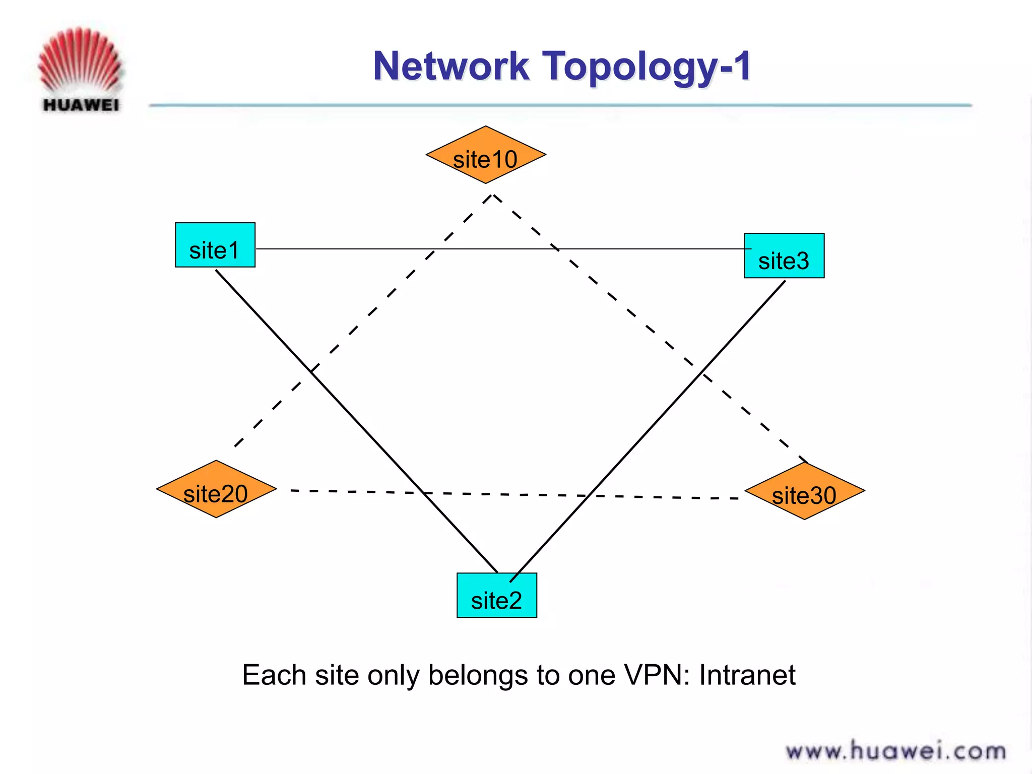
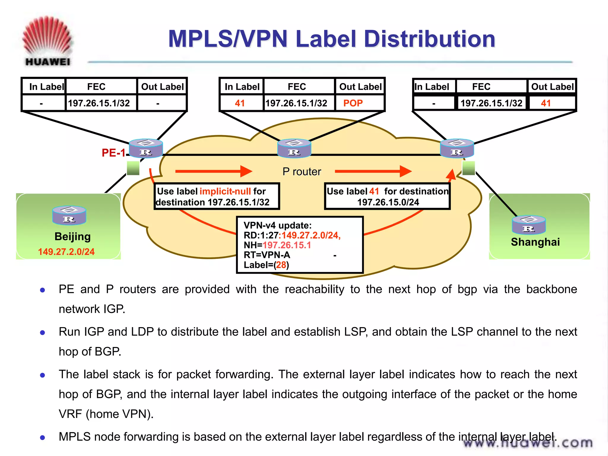
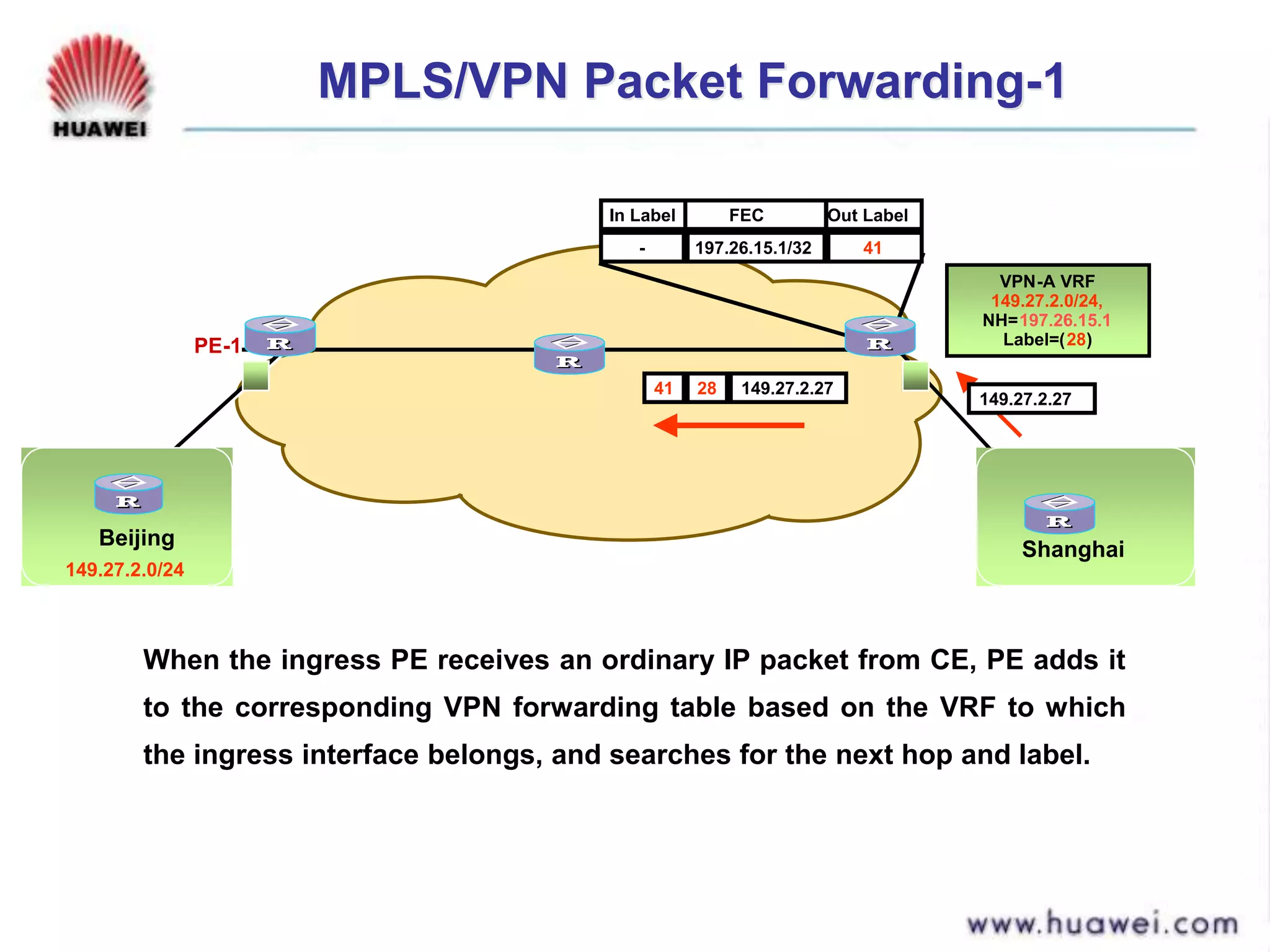
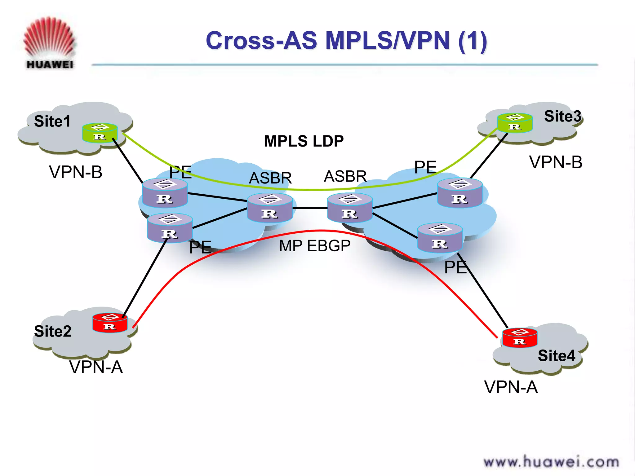
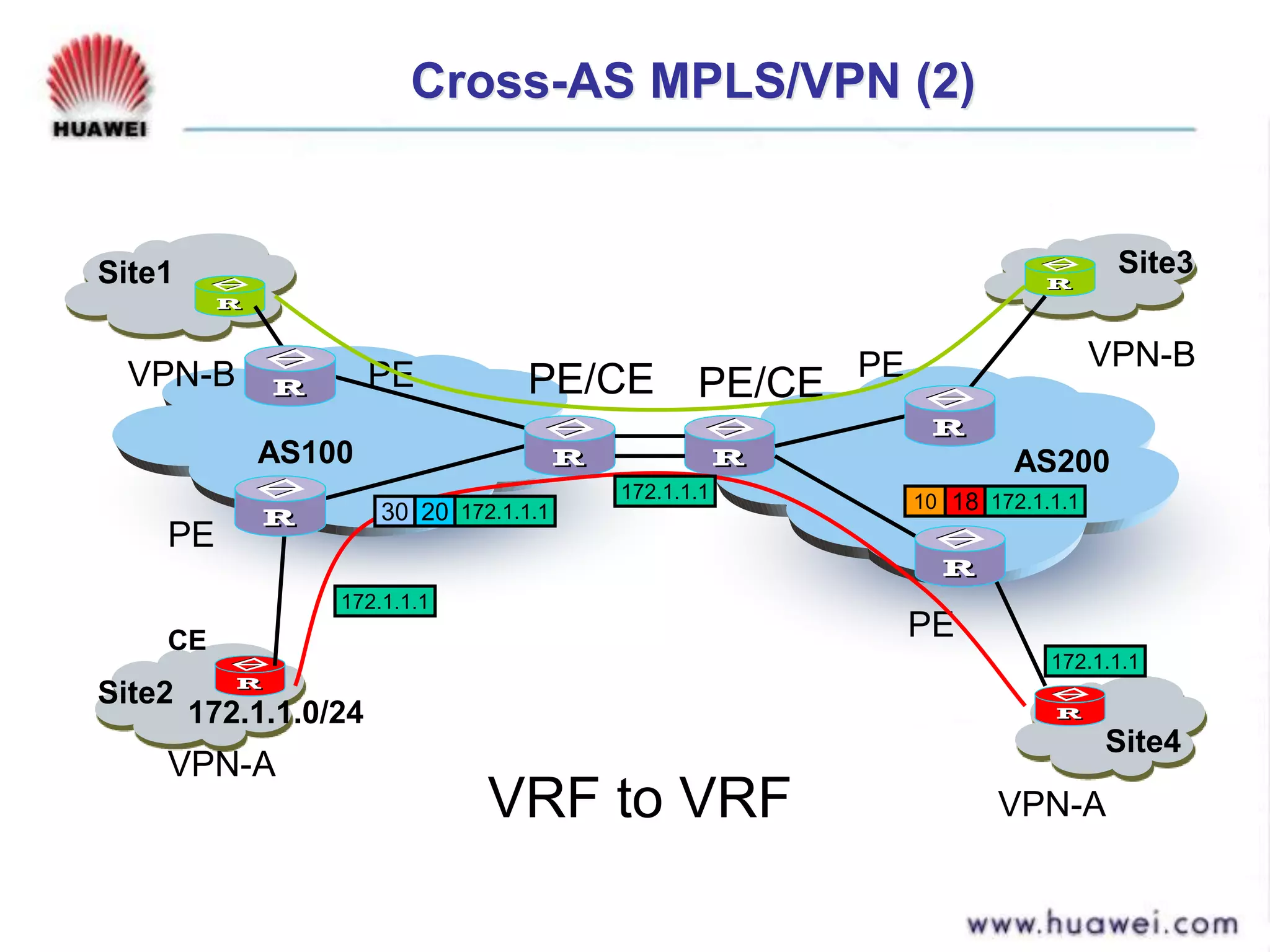
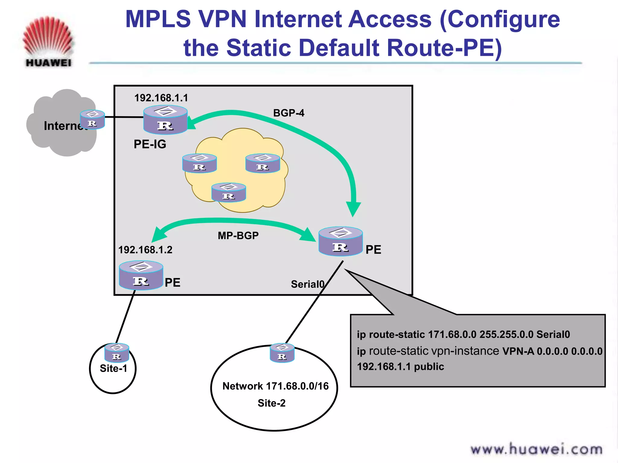
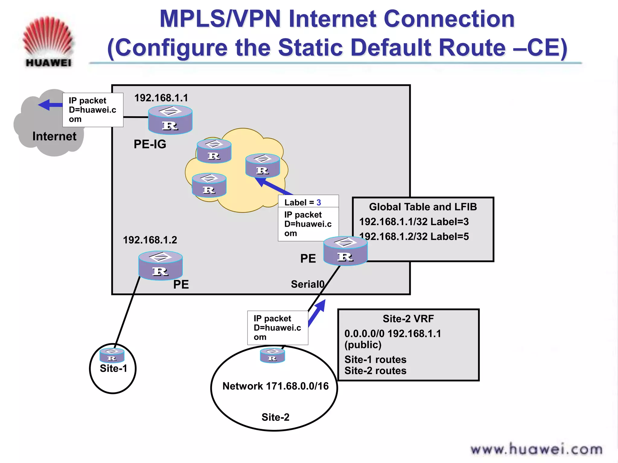
![Seller Deck - Presentation [Concert L2].PPTX](https://cdn.slidesharecdn.com/ss_thumbnails/sellerdeck-presentationconcertl2-251219171156-24982daf-thumbnail.jpg?width=640&height=640&fit=bounds)


