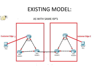
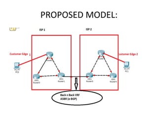
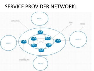
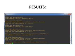
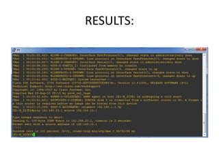
MPLS BASED VPN CONNECTIVITY
BETWEEN INTER PROVIDER ISP’S
BY,
S.PREM KUMAR
Email : prem081011@gmail.com
• VPN(VIRTUAL PRIVATE NETWORK)
• A VPN uses shared public telecom infrastructure
like internet to provide secure access to remote
offices.
• By implementing VPN we connect geographically
separated customer sites.
• Originally introduced point to point between
customer by packet switching.
• By using VPN, distinct regions customer connected
via ISP’s.
INTRODUCTION:
• VPN mainly depends on :-
 different geographical area.
 different service providers.
• For this, VPN information has to
mutually redistributed.
OBJECTIVE:
• Inter ISP’s. allow VPN information to
redistributed between adjacent MPLS.
• So client sites communicate with each
other across multiple ISP’s..
MPLS
• MPLS (MULTIPROTOCOL LABEL
SWITCHING)
• Data carrying technique for high
performance telecommunications
network.
• Based on shortest path LABELS
• Avoiding complex lookups in a routing
table.
DATA FORWARDING IN MPLS:
R4 TO R1
ARCHITECTURE BLOCKS
CONTROL PLANE
Layer 3 Protocol exchange and its related processes
examples: OSPF,BGP and Layer distribution protocols
DATA PLANE
Forwarding engine that forwards based on labels or destination IP addresses
MPLS ARCHITECTURE:
• CONTROL PLANE: IGP(OSPF),LDP
IGP: FIB(Forwarding information base) Routing
table.
LDP(Label distribution protocol):LIB(Label
information base)
• DATA PLANE: Performs functions relating to
forwarding data packets derived from control
plane.
IP ROUTING PROTOCOLS
(IGP,BGP)
IP ROUTING TABLE
LABEL INFORMATION BASE
(LIB)
IP FORWARDING TABLE-
FORWARDING
INFORMATION BASE
(FIB)
LABEL FORWARDING
INFORMATION BASE
(LFIB)
Incoming
IP packets
Outgoing IP
Packets
Incoming MPLS
packets
Outgoing
MPLS
packets
CONTROL PLANE
DATA PLANE
FORMAT OF MPLS:
• LABEL : 20 Bits (0 to19)
• COS : (Class of service)
 3 Bits (19 to 22)
 Classification of customer based on QoS.
LABEL COS BOS TTL
• BOS: (Bottom of stack)
1 Bit (22 to 23)….Multi label/One label
• TTL: Time to live ( 23 to 31)
Maximum count: 255 (2^8-1).
Incase of loop condition,the TTL will become
zero.
Maximum : 30 hops.
EXISTING MODEL:
PROPOSED MODEL:
ABR(AREA BORDER ROUTER):-
• ABR can simultaneously belong to two or
more areas, one of which must be the
backbone area.
• ABR is used to connect the backbone area and
non-backbone area.
• It could be a physical connection or a logical
connection between non-backbone area and
the backbone area.
ASBR:-
• AUTONOMUS SYSTEM BOUNDARY ROUTER.
• ASBR is a device to exchange routing
information with other AS.
• It may be a router in the region or ABR.
• If a single OSPF device imports external
routing information, it becomes an ASBR.
Method 1:BACK TO BACK VRF
• The border provider edge (PE) routers residing
in different autonomous systems function as
ASBRs.
• ASBRs are interconnected either via a single
link consisting of logical sub-interfaces or via
multiple physical links.
• VRFs are configured on the ASBRs to collect
VPN client routes.
• The single client VRF can run eBGP, RIPv2,
EIGRP, OSPF, or static routing to distribute the
VPN routes to its adjacent peer.
• eBGP : Offering better policy, scalability, and
security mechanisms
DLCI:-
• Data link connection identifier.
• Identify virtual circuits.
• Given by service provider.
• Local DLCI maps with remote IP address.
FRAME RELAY:
• Frame uses virtual interface instead of
physical interface.
• The biggest benefit of these virtual lines is
that we do not need equal physical interfaces
on router to connect them.
• We can connect multiple virtual lines with
single interface.
Method 2: ASBR TO ASBR
• In the second method, the ASBRs use MP-
eBGP to peer with each other to transport
VPN routes between autonomous systems.
• It alleviates the need to have per-VPN
configuration on the ASBRs as seen in the
back-to-back VRF method, and thus allows
VPN prefixes to be transported across multiple
providers.
• Created a scenario of 3 networks with each
configure (OSPF).
• Because internally OSPF should run inside the
network for transmission of the exterior gate
way protocol like e-BGP.
• BGP Share the information to other
autonomous system with the help of OSPF
only.
RESULTS:
SERVICE PROVIDER NETWORK:
NEED OF MPLS :
• CORE: Lakhs of entries.
• IP Lookup
• Packet are facing Latency(Delay) in the core
network.
• PE Router will look the IP routing table and
put the label and forward to core router.
• Core routers will check the L2.5 not L3.
MPLS TERMINOLOGY:
• Adding the label : PUSH operation
Router : Ingress router
• Remove the label: POP operation
Router : Egress router
• Remove and Add : SWAP operation (Core)
Router : Transit router/ LSR (Label switching
router
• CORE : Full mesh topology
VRF (VIRTUAL ROUTING AND
FORWARDING)
• VPN ADDRESS: 32 Bit IP Address + RD (64
Bit)=96 bit address (VPNv4)
• RD : Route Distinguisher ( unique for every
company given by ISP’s)
• Internally they create logical router AS:RN
eg: Autonomous system no. of BSNL :
9829:100 , 100 is for customer no.
• RT : Route target (64 bit ) which branches have
to communicate.
Back to Back VRF :
BACK TO BACK VRF :
• Service provider 1 uses the protocol BGP AS1
and service provider 2 uses protocol BGP AS2.
• Configuration of VRF is done on both ASBR
routers namely PE1-ASBR1-AS1 and PE2-
ASBR2-AS2
• Conventional routing is configured between
MPLS VPN sites to distribute IPv4 packet to its
peer.
RESULTS:
RESULTS:
ASBR to ASBR APPROACH:
ASBR TO ASBR APPROACH:
• By next hop-self-method
• ASBR1-AS1 Announces itself as next hop to
P1-AS1-RR
• Similarly ASBR2-AS2 announces itself as next
hop to P2-AS2-RR.
• New VPNv4 label has been generated
between two different AS of ASBR.
• eBGP were used between ASBR1-AS1 and
ASBR2-AS2 and assigns new VPNv4 label.
• ASBR2-AS2 receives the VPNv4 route on the
MP-eBGP session from ASBR1-AS1.
• The next hop is modified from ASBR1-AS1 to
ASBR2-AS2.
• When ASBR2-AS2 propagates these routes via
the MP-iBGP session to P1-AS2-RR the VPN
label also get modified.
• The LSP path between the PE2-AS2 to ASBR2-
AS2 were used which has modified VPN label.
RESULTS:
RESULTS:
THANK YOU

Mpls based vpn connectivity

  • 1.
    MPLS BASED VPNCONNECTIVITY BETWEEN INTER PROVIDER ISP’S BY, S.PREM KUMAR Email : prem081011@gmail.com
  • 2.
    • VPN(VIRTUAL PRIVATENETWORK) • A VPN uses shared public telecom infrastructure like internet to provide secure access to remote offices. • By implementing VPN we connect geographically separated customer sites. • Originally introduced point to point between customer by packet switching. • By using VPN, distinct regions customer connected via ISP’s. INTRODUCTION:
  • 3.
    • VPN mainlydepends on :-  different geographical area.  different service providers. • For this, VPN information has to mutually redistributed. OBJECTIVE:
  • 4.
    • Inter ISP’s.allow VPN information to redistributed between adjacent MPLS. • So client sites communicate with each other across multiple ISP’s..
  • 5.
    MPLS • MPLS (MULTIPROTOCOLLABEL SWITCHING) • Data carrying technique for high performance telecommunications network. • Based on shortest path LABELS • Avoiding complex lookups in a routing table.
  • 6.
    DATA FORWARDING INMPLS: R4 TO R1
  • 7.
    ARCHITECTURE BLOCKS CONTROL PLANE Layer3 Protocol exchange and its related processes examples: OSPF,BGP and Layer distribution protocols DATA PLANE Forwarding engine that forwards based on labels or destination IP addresses
  • 8.
    MPLS ARCHITECTURE: • CONTROLPLANE: IGP(OSPF),LDP IGP: FIB(Forwarding information base) Routing table. LDP(Label distribution protocol):LIB(Label information base) • DATA PLANE: Performs functions relating to forwarding data packets derived from control plane.
  • 9.
    IP ROUTING PROTOCOLS (IGP,BGP) IPROUTING TABLE LABEL INFORMATION BASE (LIB) IP FORWARDING TABLE- FORWARDING INFORMATION BASE (FIB) LABEL FORWARDING INFORMATION BASE (LFIB) Incoming IP packets Outgoing IP Packets Incoming MPLS packets Outgoing MPLS packets CONTROL PLANE DATA PLANE
  • 10.
    FORMAT OF MPLS: •LABEL : 20 Bits (0 to19) • COS : (Class of service)  3 Bits (19 to 22)  Classification of customer based on QoS. LABEL COS BOS TTL
  • 11.
    • BOS: (Bottomof stack) 1 Bit (22 to 23)….Multi label/One label • TTL: Time to live ( 23 to 31) Maximum count: 255 (2^8-1). Incase of loop condition,the TTL will become zero. Maximum : 30 hops.
  • 12.
  • 13.
  • 14.
    ABR(AREA BORDER ROUTER):- •ABR can simultaneously belong to two or more areas, one of which must be the backbone area. • ABR is used to connect the backbone area and non-backbone area. • It could be a physical connection or a logical connection between non-backbone area and the backbone area.
  • 15.
    ASBR:- • AUTONOMUS SYSTEMBOUNDARY ROUTER. • ASBR is a device to exchange routing information with other AS. • It may be a router in the region or ABR. • If a single OSPF device imports external routing information, it becomes an ASBR.
  • 16.
    Method 1:BACK TOBACK VRF • The border provider edge (PE) routers residing in different autonomous systems function as ASBRs. • ASBRs are interconnected either via a single link consisting of logical sub-interfaces or via multiple physical links. • VRFs are configured on the ASBRs to collect VPN client routes.
  • 17.
    • The singleclient VRF can run eBGP, RIPv2, EIGRP, OSPF, or static routing to distribute the VPN routes to its adjacent peer. • eBGP : Offering better policy, scalability, and security mechanisms
  • 19.
    DLCI:- • Data linkconnection identifier. • Identify virtual circuits. • Given by service provider. • Local DLCI maps with remote IP address.
  • 20.
    FRAME RELAY: • Frameuses virtual interface instead of physical interface. • The biggest benefit of these virtual lines is that we do not need equal physical interfaces on router to connect them. • We can connect multiple virtual lines with single interface.
  • 21.
    Method 2: ASBRTO ASBR • In the second method, the ASBRs use MP- eBGP to peer with each other to transport VPN routes between autonomous systems. • It alleviates the need to have per-VPN configuration on the ASBRs as seen in the back-to-back VRF method, and thus allows VPN prefixes to be transported across multiple providers.
  • 23.
    • Created ascenario of 3 networks with each configure (OSPF). • Because internally OSPF should run inside the network for transmission of the exterior gate way protocol like e-BGP. • BGP Share the information to other autonomous system with the help of OSPF only.
  • 24.
  • 25.
  • 26.
    NEED OF MPLS: • CORE: Lakhs of entries. • IP Lookup • Packet are facing Latency(Delay) in the core network. • PE Router will look the IP routing table and put the label and forward to core router. • Core routers will check the L2.5 not L3.
  • 27.
    MPLS TERMINOLOGY: • Addingthe label : PUSH operation Router : Ingress router • Remove the label: POP operation Router : Egress router • Remove and Add : SWAP operation (Core) Router : Transit router/ LSR (Label switching router • CORE : Full mesh topology
  • 28.
    VRF (VIRTUAL ROUTINGAND FORWARDING) • VPN ADDRESS: 32 Bit IP Address + RD (64 Bit)=96 bit address (VPNv4) • RD : Route Distinguisher ( unique for every company given by ISP’s) • Internally they create logical router AS:RN eg: Autonomous system no. of BSNL : 9829:100 , 100 is for customer no. • RT : Route target (64 bit ) which branches have to communicate.
  • 29.
  • 30.
    BACK TO BACKVRF : • Service provider 1 uses the protocol BGP AS1 and service provider 2 uses protocol BGP AS2. • Configuration of VRF is done on both ASBR routers namely PE1-ASBR1-AS1 and PE2- ASBR2-AS2 • Conventional routing is configured between MPLS VPN sites to distribute IPv4 packet to its peer.
  • 31.
  • 32.
  • 33.
    ASBR to ASBRAPPROACH:
  • 34.
    ASBR TO ASBRAPPROACH: • By next hop-self-method • ASBR1-AS1 Announces itself as next hop to P1-AS1-RR • Similarly ASBR2-AS2 announces itself as next hop to P2-AS2-RR. • New VPNv4 label has been generated between two different AS of ASBR. • eBGP were used between ASBR1-AS1 and ASBR2-AS2 and assigns new VPNv4 label.
  • 35.
    • ASBR2-AS2 receivesthe VPNv4 route on the MP-eBGP session from ASBR1-AS1. • The next hop is modified from ASBR1-AS1 to ASBR2-AS2. • When ASBR2-AS2 propagates these routes via the MP-iBGP session to P1-AS2-RR the VPN label also get modified. • The LSP path between the PE2-AS2 to ASBR2- AS2 were used which has modified VPN label.
  • 36.
  • 37.
  • 38.