SlideShare a Scribd company logo
ETTI. Lab: MPLS VPN (V2.2) Octavian Catrina, 2014
1
MPLS-based Layer 3 VPNs
Overall objective
The purpose of this lab is to study Layer 3 Virtual Private Networks (L3VPNs) created using MPLS and BGP.
A VPN is an extension of a private network that uses a public communication infrastructure (operated by a
network service provider) to interconnect a group of geographically distributed private sites. A Layer 3 VPN
provides IP connectivty between VPN sites.
The most common approach uses BGP to exchange VPN routes between provider edge routers and MPLS
label switched paths for data transport. This approach, described in RFC 4364, "BGP/MPLS IP Virtual
Private Networks" (2006), is studied in this lab.
Prerequisites
You should be familiar with the basic concepts and operation of MPLS and LDP (Label Distribution Protocol),
intra-domain and inter-domain routing using RIPv2 and BGP, as well as MPLS-based VPNs.
These topics are presented in the course material. Review them before the lab.
Case study
We consider the scenario shown in Figure 1. A network service provider (SP) operates an MPLS network
and offers VPN services. The current task is to set up VPNs for the customers A and B. The network of each
of these customers consists of two sites. The customers use private IP address space (partially overlapping).
In this example, the routers in the SP network run RIPv2 for intra-domain routing, MPLS for packet
forwarding, and LDP for label distribution. For the VPN service, the SP uses the approach based on MPLS
and BGP defined in RFC 4364 (summarized in the next section). Customer edge routers exchange VPN
routing information with the provider edge routers using RIPv2.
Figure 1. Network configuration for experiments with MPLS-based VPNs.
Summary of learning objectives
You will set up the network shown in Figure 1 and study the following topics:
 Configuration of MPLS, LDP and RIPv2 in the SP network.
 Configuration of MPLS-based L3VPNs using: VRFs (Virtual Routing and Forwarding), MP-BGP
(Multi-Protocol BGP), redistribution of VPN routes between MP-BGP and RIPv2 in VRFs, etc.
 Operation of the MPLS network and the VPNs.
During the experiments carried out in the lab, you will see how these protocols work and cooperate to
achieve the VPN service, by examining the status of the routers using Cisco IOS commands and by
inspecting the exchanged packets using a protocol analyzer.
ETTI. Lab: MPLS VPN (V2.2) Octavian Catrina, 2014
2
Overview of Layer-3 MPLS-based VPNs
Virtual Routing and Forwarding (VRF)
PE routers have to support multiple VPN customers and to provide logically separated routing for each VPN
in order to prevent acess to a VPN from other networks. The MPLS-based VPNs defined in RFC 4364
achieve this separation using a Virtual Routing/Forwarding (VRF) instance for each VPN customer.
Conceptually, VRFs are separate virtual router instances running on the same physical router (Figure 2).
Each VRF has its own:
 VPN-specific IP routing and forwarding table.
 Set of interfaces associated to the forwarding table.
 Set of rules that control the import/export of routes to/from the VPN-specific routing table.
 Set of routing protocol peers that populate with routes the VPN-specific routing table.
Moreover, VRFs also provide the means to deal with VPNs that use overlapping blocks of IP addresses. This
occurs frequently in practice, due to the widespread use of private IP address space in private networks. For
example, both private networks shown in Figure 1 use 172.16.0.0/30 and 172.16.0.4/30).
Figure 2. VRF instances in PE routers provide separation of VPN routing.
The VRFs use two mechanisms in order to handle overlapping addresses and route import/export policies:
 Route distinguisher (RD): 64-bit identifier assigned to a VPN in order to distinguish its routes in case
of overlapping address spaces.
 Route target (RT): 64-bit identifiers used to specify route import/export policies.
The RTs are exchanged as MP-BGP extended community attributes. The high order 16 bits contain the MP-
BGP extended community type and the remaining 48 bits are specified as a pair of values with the syntax
16-bit : 32-bit or 32-bit : 16-bit. We use the first variant, where the 16-bit value is the AS number, as shown in
the table below. We assume that the AS number of the SP network is ASN = 1. RD values are similar.
VRF/VPN RD Import RT Export RT
vpn_a 1:1 1:1 1:1
vpn_b 1:2 1:2 1:2
By combining a VPN RD and a VPN route prefix we obtain a unique route prefix that can be handled by the
MP-BGP routing protocol. We'll refer to this addressing scheme as the VPNv4 address family.
Control plane operation
Figure 3 is a high level view of the end-to-end propagation of VPN routes, taking as example the VPN routes
for destination VPN A, Site 1. Figure 4 provides more details about propagation of VPN routes as well as the
distribution of MPLS labels using LDP.
The propagation of the VPN routes is summarized below:
1. An IP route to a VPN site is first exchanged using an IGP between a CE router and the associated
VRF in a PE router. We use RIPv2. CE1A advertises to VRF vpn_a in PE1 a route to Site 1 of VPN
A, with prefix 172.16.1.0/24. This route is inserted in the routing table of VRF vpn_a.
2. The VRF adds the RD assigned to the VPN and then redistributes the resulting VPNv4 route into
MP-BGP (Multi-Protocol BGP), together with the VPN Label and the exported RT.
ETTI. Lab: MPLS VPN (V2.2) Octavian Catrina, 2014
3
3. MP-BGP is responsible for the exchange of VPN routes between the PE routers. PE1 advertises the
VPNv4 route to PE2 using MP-iBGP and Next-Hop itself. VPN-specific information is carried in MP-
BGP attributes (VPNv4 prefix, VPN label, RT).
4. VRF vpn_a at PE2 imports the route, since the local import RT matches the RT in the route. The
IPv4 route is inserted in its routing table, with PE1 as next hop. The VPN Label (LA) is also recorded.
5. VRF vpn_a at PE2 advertises the IPv4 route to router CE2A using an IGP (RIPv2). This completes
the distribution of the route to 172.16.1.0/24 (Site 1 of VPN A).
Figure 3. End-to-end route propagation.
Observe that the VPN routes are processed only by the PE routers. The other routers in the SP network
need not know anything about VPN addresses and routes. In particular, the IGP running within the SP
network is not involved in VPN route propagation (it supports the VPN only by providing internal routes
needed to set up LSPs between PE routers). We use RIPv2 in the SP network.
Figure 4. Control plane: Route and label propagation.
Data plane operation
Figure 5 shows the packet forwarding for VPN A, from Site 1 to Site 2, after the final configuration of the
MPLS-based VPNs. The MPLS packets carry a label stack consisting of two labels:
 The top label (L1, L2) corresponds to the LSP between PE1 and PE2 set up automatically by LDP.
 The bottom label (LA) is the VPN label assigned to the VPN by the egress router (in this example, the
label assigned to VPN A by PE2). This label allows the egress router to demultiplex the packet flow
received on the LSP, indentifying the packets belonging to each VPN.
Figure 5 shows that P1 pops the top label, instead of PE1. This procedure is called penultimate hop popping
(PHP), i.e., an LSP label is removed by the penultimate router, rather than the last router, and was requested
by PE1 during label distribution (Implicit-Null label). This avoids an unnecessary label lookup at PE1, and it is
the default behavior of Cisco routers.
ETTI. Lab: MPLS VPN (V2.2) Octavian Catrina, 2014
4
Figure 5. Packet forwarding in MPLS-based VPN.
1. Network setup
The experiments are carried out using the network shown in Figure 1. The SP network consists of the edge
routers PE1 and PE2 and the internal routers P1 and P2. The SP network interconnects two sites of
Customer A (edge routers CE1A and CE2A) and two sites of Customer B (edge routers CE1B and CE2B).
All routers run Cisco IOS and are configured with Fast Ethernet interfaces.
Your task is to set up for each customer a VPN that interconnects its two sites. The instructions given in the
following assume that the experiments are carried out using the network emulator GNS3.
1.1. Load the initial GNS project.
You start with a GNS project that contains the network shown in Figure 1. The IP addresses are already
configured, except for the VRF interfaces. Check the initial configuration of the routers.
1.2. Start the routers and check the CPU load.
Start a router using GNS (right-click on the router and select Start) and then check the CPU load (on
Windows, start the Task Manager and select the Performance tab). Wait until the router boots up.
If the CPU load does not decrease to a low level, adjust the Idle PC parameter (right-click on the router and
select Idle-PC); ask the instructor if necessary.
Then start the entire network and check that the CPU load falls to a low level once all the routers boot up.
1.3. Start router consoles.
Start consoles for all the routers using GNS (Console button in the toolbar). Each console should show the
Cisco CLI prompt router-name# for the privileged mode, which allows you to enter any command for
configuring the router or examining its status.
You have to carry out a quite lengthy, incremental configuration. To make this process faster and less error
prone, use the following procedure:
 At each step, edit using a text editor the batches of commands for all the routers you configure and
then copy each batch from the text editor to the router's console window (right-click).
 Before proceeding to the next step, verify if the router configuration and operation are correct, save
the configuration using the IOS command "copy run start" or "write" and then save the GNS project.
2. Configure interior routing in the SP network
We start by setting up our SP network, and afterwards we'll create the VPNs for our clients.
The IP addresses should already be configured now, so we can proceed to configure interior routing. We use
for this purpose RIPv2.
2.1. Configure RIPv2 for interior routing in the SP network (routers PE1, PE2, P1, and P2).
The configuration commands for PE1 are listed below (starting in global configuration mode). The
configuration of the other routers is similar.
ETTI. Lab: MPLS VPN (V2.2) Octavian Catrina, 2014
5
router rip
version 2
network 10.0.0.0
Begin RIP configuration (and start RIP).
Set RIP version 2.
Enable RIP on interfaces connected to 10.0.0.0/8.
2.2. Test and troubleshoot internal routing in the SP network.
- Examine the status of the SP routers using the commands show ip protocols and show ip route.
Does the router receive information from all its neighbors in the SP network? Do you see routes to all
destinations in the SP network (all links and the loopback interfaces)?
- Test the connectivity between PE1 and PE2 using ping.
2.3. Save the configuration of the routers and the GNS project.
3. Configure MPLS in the SP network
We're now going to configure MPLS in the SP network and examine using the protocol analyzer the packets
exchanged by LDP to set up adjacencies and distribute labels.
3.1. Capture the traffic on interface f2/0 of PE1 (link between PE1 and P1).
3.2. Configure MPLS and LDP in the SP network (routers PE1, PE2, P1, and P2).
Enable MPLS for all interfaces connected to the SP network (but not on the interfaces connected to the client
networks). You should also have CEF (Cisco Express Forwarding) enabled for each SP router. The
configuration commands for PE1 are listed below (similar for the others):
ip cef
mpls label protocol ldp
mpls ldp router-id Loopback0
interface f2/0
mpls ip
Enable CEF
Set LDP for MPLS label distribution.
Configure the LDP Router-ID
Activate MPLS on interface f0/0
3.3. Check if MPLS and LDP are working properly.
For the current (default) configuration, LDP works as follows:
 The router assigns labels to prefix-based FECs (destination prefixes found in the routing table),
using per-platform label space.
 Then the router sends its own label bindings to its LDP-enabled neighbors, using independent,
downstream unsolicited label distribution.
- Examine the status of the LDP sessions established by the router with its neighbors:
show mpls ldp neighbor
Has the router successfully established LDP sessions (Open state) with all its neighbors?
- Examine the router's Label Information Base (LIB):
show mpls ldp bindings
Note that Cisco IOS uses here the term "tag" instead of "label" (hence tsr = LSR, tib = LIB).
Compare the information in the LIB with the routing table. Do you see label bindings for all (applicable)
destinations? Do you see, for each destination, a local binding as well as remote bindings from all LDP
neighbors? What label retention policy is being used?
- Examine the router's MPLS forwarding table, also called Forwarding Information Base (FIB):
show mpls forwarding-table
ETTI. Lab: MPLS VPN (V2.2) Octavian Catrina, 2014
6
The FIB is built based on the routing table and the LIB, and is used for MPLS packet forwarding. LSPs are
(implicitly) defined by matching FIB entries along the path to a destination prefix. Figure out how the FIB is
built and used by comparing the information in the FIB entries with the routing table and the LIB.
- Test the connectivity between PE1 and PE2 using ping (try the addresses of the loopback interfaces).
3.4. Examine the exchanged messages using the protocol analyzer.
Start the Wireshark protocol analyzer (from GNS3) in order to examine the packets captured after enabling
MPLS and LDP.
- In Wireshark, set ldp as filter expression, in order to display the LDP messages. Examine the messages
exchanged by PE1 and P1 during the LDP session setup. Compare the label bindings in the LDP messages
with the information displayed by the command show mpls ldp bindings.
- In Wireshark, set icmp as filter expression, in order to display the ICMP messages exchanged during the
test. Do you see MPLS headers for all ICMP messages? If not, why? (Hint: The routers apply by default
Penultimate Hop Popping.)
3.5. Save the configuration of the routers and the GNS project.
4. Configure RIPv2 on the customer edge (CE) routers
We can now begin the configuration of the VPNs for our two customers.
We start by completing the configuration of the CE routers. The interfaces should already be configured, so
we can proceed to the configuration of RIPv2.
4.1. Configure and start RIPv2 on the routers CE1A, CE2A, CE1B, and CE2B.
The configuration commands for CE1A are listed below (similar for the others, don't forget 172.17.0.0).
router rip
version 2
network 172.16.0.0
no auto-summary
Begin RIP configuration.
Set RIP version 2.
Enable RIP on interfaces connected to 172.16.0.0/16.
Disable route summarization.
4.2. Check if RIPv2 is working properly.
Examine the current status using the commands show ip protocols and show ip route.
4.3. Save the configuration of the routers and the GNS project.
5. Create the VRFs and configure their interfaces
5.1. Create the VRFs associated to the VPNs on PE1 and PE2.
A VRF is identified by a name (unique within a physical router). We call vpn_a and vpn_b the VRFs for VPN
A and VPN B, respectively. The configuration commands for PE1 are listed below (similar for PE2).
ip vrf vpn_a
rd 1:1
route-target export 1:1
route-target import 1:1
ip vrf vpn_b
rd 1:2
route-target export 1:2
Configure the VRF vpn_a
Set the route distinguisher to 1:1.
Set the imported and exported route target to 1:1.
Configure the VRF vpn_b
Set the route distinguisher to 1:2.
Set the imported and exported route target to 1:2.
ETTI. Lab: MPLS VPN (V2.2) Octavian Catrina, 2014
7
route-target import 1:2
5.2. Configure the VRF interfaces on PE1 and PE2.
The configuration commands for PE1 are listed below (similar for PE2).
interface FastEthernet0/0
ip vrf forwarding vpn_a
ip address 172.16.0.1 255.255.255.252
no shutdown
interface FastEthernet1/0
ip vrf forwarding vpn_b
ip address 172.16.0.1 255.255.255.252
no shutdown
Configure the interface f0/0 .
Associate the interface with VRF vpn_a.
Assign the IP address and subnet mask to the interface.
Turn on the interface.
Configure the interface f1/0.
Associate the interface with VRF vpn_b.
Assign the IP address and subnet mask to the interface.
Turn on the interface.
5.3. Examine the initial VRF configuration and status on PE1 and PE2.
show ip vrf
show ip vrf detail
show ip vrf interfaces
show ip route
show ip route vrf vpn_a
show ip route vrf vpn_b
Status/configuration of the VRFs, summary
and details.
Status/configuration of the VRF interfaces.
Global routing table.
VRF routing table for VRF vpn_a.
VRF routing table for VRF vpn_b.
Is everything configured and working correctly?
5.4. Analysis of the address configuration.
According to the address assignment in Figure 1, at step 5.1 you configured the same address for the
interfaces f0/0 and f1/0 of router PE1. Can the network operate correctly with this configuration? Why?
Furthermore, Figure 1 shows that you have to configure the address 172.16.0.5 to the interfaces f0/0 and
f1/0 of router PE2. Could we have assigned the same addresses as for PE1? Why?
5.5. Save the configuration of the routers and the GNS project.
6. Configure RIPv2 on the VRFs
6.1. Configure RIPv2 to exchange routes between each CE router and the associated VRF instance.
The configuration commands for the PE1 VRFs are listed below (similar on PE2). To configure RIPv2 routing
for IPv4 on a VRF instance, you have to use the command address-family ipv4 vrf.
router rip
address-family ipv4 vrf vpn_a
network 172.16.0.0
no auto-summary
exit-address-family
address-family ipv4 vrf vpn_b
network 172.16.0.0
no auto-summary
exit-address-family
Begin (resume) RIPv2 configuration.
Run RIP for VRF vpn_a, on interfaces connected to the
(IPv4) prefix 172.16.0.0/16.
Run RIP for VRF vpn_b, on interfaces connected to the
(IPv4) prefix 172.16.0.0/16 (the address spaces used by
the two customers overlap).
6.2. Examine the current configuration and status of the VRFs on PE1 and PE2.
ETTI. Lab: MPLS VPN (V2.2) Octavian Catrina, 2014
8
show ip vrf
show ip vrf detail
show ip vrf interfaces
show ip route
show ip route vrf vpn_a
show ip route vrf vpn_b
Status/configuration of the VRFs, summary
and details.
Status/configuration of the VRF interfaces.
Global routing table.
VRF routing table for VRF vpn_a.
VRF routing table for VRF vpn_b.
Recall that on PE routers we have 3 separate routing tables (2 VRF tables and a global table).
Is everything working correctly? Do you see now all the routes?
6.3. Examine the current status of the CE routers.
Examine the routing tables of the CE routers (show ip route).
Test the connectivity between CE routers and PE routers using ping.
6.4. Save the configuration of the routers (PE1, PE2) and the GNS project.
7. Configure MP-BGP on PE routers
The VPN routes will be propagated between PE routers using MP-BGP. We'll configure this in several steps.
7.1. Configure and start BGP on PE1 and PE2.
Start BGP on PE1 and PE2 and establish a BGP connection between them. The AS number (ASN) of the SP
network is ASN = 1.
The configuration commands for PE1 (10.100.255.1) are listed below (symmetric configuration for PE2).
router bgp 1
network 10.100.255.1 mask 255.255.255.255
neighbor 10.100.255.4 remote-as 1
neighbor 10.100.255.4 update-source Loopback0
no synchronization
no auto-summary
Begin BGP configuration for the AS with ASN = 1.
Advertise BGP routes to the prefix 10.100.255.1/32.
Establish a BGP connection to 10.100.255.4 (PE1) in
AS 1 (iBGP), using as source address the address of
the interface Loopback0.
7.2. Configure MP-BGP for VPNs on PE1 and PE2.
The configuration commands for PE1 are listed below (symmetric configuration for PE2).
router bgp 1
address-family vpnv4
neighbor 10.100.255.4 activate
neighbor 10.100.255.4 send-community extended
neighbor 10.100.255.4 next-hop-self
Begin (resume) BGP configuration for AS 1.
Begin configuration for the address family vpnv4.
For the BGP connection to 10.100.255.4: advertise
vpnv4 routes; send Extended Community attributes
(for RT); set the Next-Hop attribute of the routes to
PE1's own address.
7.3. Examine the current BGP configuration and status.
sh ip bgp summary
sh ip bgp all
sh ip route
sh ip bgp neighbors
ETTI. Lab: MPLS VPN (V2.2) Octavian Catrina, 2014
9
Is there a BGP session between PE1 and PE2?
Do you see all the routes you expected in the routing tables?
Why is it necessary to ask MP-BGP to set the Next-Hop attribute of the advertised VPN routes to the
sender's own address (next-hop-self)? How will this affect VPN traffic forwarding in the SP network?
7.4. Save the configuration of the routers (PE1, PE2) and the GNS project.
8. Configure route redistribution between RIPv2 and MP-BGP
We need to redistribute the VPN routes between RIPv2 and BGP in the VRFs, in order to enable the
propagation of the VPN routes between the CE routers, via the PE routers.
8.1. Configure RIP to redistribute BGP routes, on PE1 and PE2.
The configuration commands for PE1 are listed below (similar for PE2):
router rip
address-family ipv4 vrf vpn_a
redistribute bgp 1 metric transparent
exit-address-family
address-family ipv4 vrf vpn_b
redistribute bgp 1 metric transparent
Begin (resume) RIPv2 configuration.
Begin configuration for address family ipv4 for VRF vpn_a.
Redistribute BGP routes (for AS 1) into RIP, preserving the
RIP metric.
Similar for VRF vpn_b.
8.2. Configure BGP to redistribute RIP routes, for the VRFs created in PE1 and PE2.
The configuration commands for PE1 are listed below (same commands for PE2):
router bgp 1
address-family ipv4 vrf vpn_a
redistribute rip
no auto-summary
no synchronization
exit-address-family
address-family ipv4 vrf vpn_b
redistribute rip
no auto-summary
no synchronization
Begin (resume) BGP configuration for AS 1.
Begin configuration for address family ipv4 for VRF vpn_a.
Redistribute RIP routes from VRF vpn_a into BGP.
Similar for VRF vpn_b.
8.3. Examine the current BGP configuration and status.
sh ip bgp summary
sh ip bgp all
sh ip route
sh ip route vrf vpn_a
sh ip route vrf vpn_b
You should find now all the VPN routes in the BGP routing tables of PE1 and PE2.
Do you also see all the VPN routes in the PE/VRF and CE routing tables?
8.4. Save the configuration of the routers (PE1, PE2) and the GNS project.
ETTI. Lab: MPLS VPN (V2.2) Octavian Catrina, 2014
10
9. VPN operation (data and control planes)
At this point, we completed the VPN configuration. The VPN routes should be present in the routing tables of
the VRFs and of the CE routers.
9.1. Test the connectivity between the two sites of the same VPN.
Use ping, e.g., from CE1A to CE2A:
ping 172.16.2.1 source 172.16.1.1 repeat 10
9.2. Examine the data plane operation using the protocol analyzer.
Capture the traffic at the interface f1/0 of P1 (link between P1 and P2) using GNS3. Generate data traffic
between the VPN sites using ping. Examine the exchanged packets using Wireshark (filter icmp).
Compare the MPLS headers with the contents of the Label Information Base (show mpls ldp bindings)
and Forwarding Information Base (show mpls forwarding-table) of P1 and P2.
9.3. Examine the control plane operation using the protocol analyzer.
Capture the traffic at the interface f1/0 of P1 (link between P1 and P2) using GNS3.
- Turn off the interface f0/0 of CE1A (shutdown).
Examine the exchanged BGP packets using Wireshark (filter bgp).
What is the effect of turning off this interface on the VPNs? How does BGP learn about this event? How
does BGP react to the event?
- Turn on the interface f0/0 of CE1A (no shutdown).
Examine the exchanged BGP packets using Wireshark (filter bgp).
Same questions as above.
10. Optional
10.1. Is it possible to transfer IP packets between a site of VPN A and a site of VPN B with the current
configuration? Why?
10.2. Modify the configuration of the routers PE1 and PE2 such that:
(a) Site 1 of VPN A can communicate with the other site of VPN A as well as with Site 1 of VPN B.
(b) Site 2 of VPN A can only communicate with Site 1 of VPN A.
(c) Site 2 of VPN B can only communicate with Site 1 of VPN B.

More Related Content

What's hot

MPLS L3 VPN Tutorial, by Nurul Islam Roman [APNIC 38]
MPLS L3 VPN Tutorial, by Nurul Islam Roman [APNIC 38]MPLS L3 VPN Tutorial, by Nurul Islam Roman [APNIC 38]
MPLS L3 VPN Tutorial, by Nurul Islam Roman [APNIC 38]
APNIC
 
Protocole OSPF
Protocole OSPFProtocole OSPF
Protocole OSPF
Thomas Moegli
 
MPLS + BGP Presentation
MPLS + BGP PresentationMPLS + BGP Presentation
MPLS + BGP Presentation
Gino McCarty
 
Troubleshooting BGP
Troubleshooting BGPTroubleshooting BGP
Troubleshooting BGP
APNIC
 
Junos vs ios Troubleshooting comands
Junos vs ios Troubleshooting comands Junos vs ios Troubleshooting comands
Junos vs ios Troubleshooting comands
sandeep kumar
 
MPLS Layer 3 VPN
MPLS Layer 3 VPN MPLS Layer 3 VPN
MPLS Layer 3 VPN
NetProtocol Xpert
 
Juniper mpls best practice part 2
Juniper mpls best practice   part 2Juniper mpls best practice   part 2
Juniper mpls best practice part 2
Febrian ‎
 
Mpls Traffic Engineering ppt
Mpls Traffic Engineering pptMpls Traffic Engineering ppt
Mpls Traffic Engineering pptNitin Gehlot
 
MPLS
MPLSMPLS
MPLS-VPN
MPLS-VPNMPLS-VPN
MPLS-VPN
Eric Maxime
 
Cisco Live! :: Carrier Ethernet 2.0 :: BRKSPG-2720 | Las Vegas July/2016
Cisco Live! :: Carrier Ethernet 2.0 :: BRKSPG-2720 | Las Vegas July/2016Cisco Live! :: Carrier Ethernet 2.0 :: BRKSPG-2720 | Las Vegas July/2016
Cisco Live! :: Carrier Ethernet 2.0 :: BRKSPG-2720 | Las Vegas July/2016
Bruno Teixeira
 
VRF (virtual routing and forwarding)
VRF (virtual routing and forwarding)VRF (virtual routing and forwarding)
VRF (virtual routing and forwarding)
Netwax Lab
 
Soutenance Finale
Soutenance FinaleSoutenance Finale
Soutenance Finale
Slim Bejaoui
 
Fabric Path PPT by NETWORKERS HOME
Fabric Path PPT by NETWORKERS HOMEFabric Path PPT by NETWORKERS HOME
Fabric Path PPT by NETWORKERS HOME
networkershome
 
MPLS on Router OS V7 - Part 2
MPLS on Router OS V7 - Part 2MPLS on Router OS V7 - Part 2
MPLS on Router OS V7 - Part 2
GLC Networks
 
MPLS Traffic Engineering
MPLS Traffic EngineeringMPLS Traffic Engineering
MPLS Traffic Engineering
APNIC
 
STP (spanning tree protocol)
STP (spanning tree protocol)STP (spanning tree protocol)
STP (spanning tree protocol)
Netwax Lab
 
Bgp tutorial for ISP
Bgp tutorial for ISPBgp tutorial for ISP
Bgp tutorial for ISP
Wahyu Nasution
 
Deploying IP/MPLS VPN - Cisco Networkers 2010
Deploying IP/MPLS VPN - Cisco Networkers 2010Deploying IP/MPLS VPN - Cisco Networkers 2010
Deploying IP/MPLS VPN - Cisco Networkers 2010Febrian ‎
 
VPLS Fundamental
VPLS FundamentalVPLS Fundamental
VPLS Fundamental
Reza Farahani
 

What's hot (20)

MPLS L3 VPN Tutorial, by Nurul Islam Roman [APNIC 38]
MPLS L3 VPN Tutorial, by Nurul Islam Roman [APNIC 38]MPLS L3 VPN Tutorial, by Nurul Islam Roman [APNIC 38]
MPLS L3 VPN Tutorial, by Nurul Islam Roman [APNIC 38]
 
Protocole OSPF
Protocole OSPFProtocole OSPF
Protocole OSPF
 
MPLS + BGP Presentation
MPLS + BGP PresentationMPLS + BGP Presentation
MPLS + BGP Presentation
 
Troubleshooting BGP
Troubleshooting BGPTroubleshooting BGP
Troubleshooting BGP
 
Junos vs ios Troubleshooting comands
Junos vs ios Troubleshooting comands Junos vs ios Troubleshooting comands
Junos vs ios Troubleshooting comands
 
MPLS Layer 3 VPN
MPLS Layer 3 VPN MPLS Layer 3 VPN
MPLS Layer 3 VPN
 
Juniper mpls best practice part 2
Juniper mpls best practice   part 2Juniper mpls best practice   part 2
Juniper mpls best practice part 2
 
Mpls Traffic Engineering ppt
Mpls Traffic Engineering pptMpls Traffic Engineering ppt
Mpls Traffic Engineering ppt
 
MPLS
MPLSMPLS
MPLS
 
MPLS-VPN
MPLS-VPNMPLS-VPN
MPLS-VPN
 
Cisco Live! :: Carrier Ethernet 2.0 :: BRKSPG-2720 | Las Vegas July/2016
Cisco Live! :: Carrier Ethernet 2.0 :: BRKSPG-2720 | Las Vegas July/2016Cisco Live! :: Carrier Ethernet 2.0 :: BRKSPG-2720 | Las Vegas July/2016
Cisco Live! :: Carrier Ethernet 2.0 :: BRKSPG-2720 | Las Vegas July/2016
 
VRF (virtual routing and forwarding)
VRF (virtual routing and forwarding)VRF (virtual routing and forwarding)
VRF (virtual routing and forwarding)
 
Soutenance Finale
Soutenance FinaleSoutenance Finale
Soutenance Finale
 
Fabric Path PPT by NETWORKERS HOME
Fabric Path PPT by NETWORKERS HOMEFabric Path PPT by NETWORKERS HOME
Fabric Path PPT by NETWORKERS HOME
 
MPLS on Router OS V7 - Part 2
MPLS on Router OS V7 - Part 2MPLS on Router OS V7 - Part 2
MPLS on Router OS V7 - Part 2
 
MPLS Traffic Engineering
MPLS Traffic EngineeringMPLS Traffic Engineering
MPLS Traffic Engineering
 
STP (spanning tree protocol)
STP (spanning tree protocol)STP (spanning tree protocol)
STP (spanning tree protocol)
 
Bgp tutorial for ISP
Bgp tutorial for ISPBgp tutorial for ISP
Bgp tutorial for ISP
 
Deploying IP/MPLS VPN - Cisco Networkers 2010
Deploying IP/MPLS VPN - Cisco Networkers 2010Deploying IP/MPLS VPN - Cisco Networkers 2010
Deploying IP/MPLS VPN - Cisco Networkers 2010
 
VPLS Fundamental
VPLS FundamentalVPLS Fundamental
VPLS Fundamental
 

Similar to MPLS-based Layer 3 VPNs.pdf

ODA000017 MPLS VPN(L3).ppt
ODA000017 MPLS VPN(L3).pptODA000017 MPLS VPN(L3).ppt
ODA000017 MPLS VPN(L3).ppt
marwan76
 
Mpls Services
Mpls ServicesMpls Services
Mpls Services
Kristof De Brouwer
 
IP Infusion Application Note for 4G LTE Fixed Wireless Access
IP Infusion Application Note for 4G LTE Fixed Wireless AccessIP Infusion Application Note for 4G LTE Fixed Wireless Access
IP Infusion Application Note for 4G LTE Fixed Wireless Access
Dhiman Chowdhury
 
Mpls vpn.rip
Mpls vpn.ripMpls vpn.rip
Mpls vpn.rip
farhanica
 
ISP core routing project
ISP core routing projectISP core routing project
ISP core routing project
vishal sharma
 
Nokia L3 VPN Configuration Guide
Nokia L3 VPN Configuration GuideNokia L3 VPN Configuration Guide
Nokia L3 VPN Configuration Guide
Abel Saduwa
 
Group 1
Group 1Group 1
Group 1
lifetobeart
 
Ccnav5.org ccna 3-v50_practice_final_exam_2014
Ccnav5.org ccna 3-v50_practice_final_exam_2014Ccnav5.org ccna 3-v50_practice_final_exam_2014
Ccnav5.org ccna 3-v50_practice_final_exam_2014Đồng Quốc Vương
 
E routing final exam ccna 2 46
E routing final exam ccna 2 46E routing final exam ccna 2 46
E routing final exam ccna 2 46lslsc
 
Multiprotocol label switching (mpls) - Networkshop44
Multiprotocol label switching (mpls)  - Networkshop44Multiprotocol label switching (mpls)  - Networkshop44
Multiprotocol label switching (mpls) - Networkshop44
Jisc
 
International Journal of Engineering Research and Development (IJERD)
International Journal of Engineering Research and Development (IJERD)International Journal of Engineering Research and Development (IJERD)
International Journal of Engineering Research and Development (IJERD)
IJERD Editor
 
OSPF (Open Shortest Path First) Case Study: Anil Nembang
OSPF (Open Shortest Path First) Case Study: Anil NembangOSPF (Open Shortest Path First) Case Study: Anil Nembang
OSPF (Open Shortest Path First) Case Study: Anil NembangAnil Nembang
 
Cube2012 high capacity service provider design using gpmls for ip next genera...
Cube2012 high capacity service provider design using gpmls for ip next genera...Cube2012 high capacity service provider design using gpmls for ip next genera...
Cube2012 high capacity service provider design using gpmls for ip next genera...Ashish Tanwer
 
MPLS Deployment Chapter 1 - Basic
MPLS Deployment Chapter 1 - BasicMPLS Deployment Chapter 1 - Basic
MPLS Deployment Chapter 1 - Basic
Ericsson
 
Performance Analysis of Routing Protocols RIP, OSPF and EIGRP
Performance Analysis of Routing Protocols RIP, OSPF and EIGRPPerformance Analysis of Routing Protocols RIP, OSPF and EIGRP
Performance Analysis of Routing Protocols RIP, OSPF and EIGRP
IRJET Journal
 
All in one q & ans
All in one q & ansAll in one q & ans
All in one q & ansRavi Kodoli
 
C0343015019
C0343015019C0343015019
C0343015019
ijceronline
 
RIP and OSPF
RIP and OSPFRIP and OSPF
RIP and OSPF
MusharratTabassum
 
ITNE2003 -  AssignmentLearning ObjectivesUpon completion of this.docx
ITNE2003 -  AssignmentLearning ObjectivesUpon completion of this.docxITNE2003 -  AssignmentLearning ObjectivesUpon completion of this.docx
ITNE2003 -  AssignmentLearning ObjectivesUpon completion of this.docx
sleeperfindley
 

Similar to MPLS-based Layer 3 VPNs.pdf (20)

ODA000017 MPLS VPN(L3).ppt
ODA000017 MPLS VPN(L3).pptODA000017 MPLS VPN(L3).ppt
ODA000017 MPLS VPN(L3).ppt
 
Mpls Services
Mpls ServicesMpls Services
Mpls Services
 
IP Infusion Application Note for 4G LTE Fixed Wireless Access
IP Infusion Application Note for 4G LTE Fixed Wireless AccessIP Infusion Application Note for 4G LTE Fixed Wireless Access
IP Infusion Application Note for 4G LTE Fixed Wireless Access
 
Mpls vpn.rip
Mpls vpn.ripMpls vpn.rip
Mpls vpn.rip
 
ISP core routing project
ISP core routing projectISP core routing project
ISP core routing project
 
Nokia L3 VPN Configuration Guide
Nokia L3 VPN Configuration GuideNokia L3 VPN Configuration Guide
Nokia L3 VPN Configuration Guide
 
Group 1
Group 1Group 1
Group 1
 
Ccnav5.org ccna 3-v50_practice_final_exam_2014
Ccnav5.org ccna 3-v50_practice_final_exam_2014Ccnav5.org ccna 3-v50_practice_final_exam_2014
Ccnav5.org ccna 3-v50_practice_final_exam_2014
 
E routing final exam ccna 2 46
E routing final exam ccna 2 46E routing final exam ccna 2 46
E routing final exam ccna 2 46
 
Multiprotocol label switching (mpls) - Networkshop44
Multiprotocol label switching (mpls)  - Networkshop44Multiprotocol label switching (mpls)  - Networkshop44
Multiprotocol label switching (mpls) - Networkshop44
 
International Journal of Engineering Research and Development (IJERD)
International Journal of Engineering Research and Development (IJERD)International Journal of Engineering Research and Development (IJERD)
International Journal of Engineering Research and Development (IJERD)
 
OSPF (Open Shortest Path First) Case Study: Anil Nembang
OSPF (Open Shortest Path First) Case Study: Anil NembangOSPF (Open Shortest Path First) Case Study: Anil Nembang
OSPF (Open Shortest Path First) Case Study: Anil Nembang
 
Cube2012 high capacity service provider design using gpmls for ip next genera...
Cube2012 high capacity service provider design using gpmls for ip next genera...Cube2012 high capacity service provider design using gpmls for ip next genera...
Cube2012 high capacity service provider design using gpmls for ip next genera...
 
MPLS Deployment Chapter 1 - Basic
MPLS Deployment Chapter 1 - BasicMPLS Deployment Chapter 1 - Basic
MPLS Deployment Chapter 1 - Basic
 
Performance Analysis of Routing Protocols RIP, OSPF and EIGRP
Performance Analysis of Routing Protocols RIP, OSPF and EIGRPPerformance Analysis of Routing Protocols RIP, OSPF and EIGRP
Performance Analysis of Routing Protocols RIP, OSPF and EIGRP
 
All in one q & ans
All in one q & ansAll in one q & ans
All in one q & ans
 
C0343015019
C0343015019C0343015019
C0343015019
 
RIP and OSPF
RIP and OSPFRIP and OSPF
RIP and OSPF
 
Arun project-Final
Arun project-FinalArun project-Final
Arun project-Final
 
ITNE2003 -  AssignmentLearning ObjectivesUpon completion of this.docx
ITNE2003 -  AssignmentLearning ObjectivesUpon completion of this.docxITNE2003 -  AssignmentLearning ObjectivesUpon completion of this.docx
ITNE2003 -  AssignmentLearning ObjectivesUpon completion of this.docx
 

More from Huynh MVT

MPLS Virtual Private Networks.pdf
MPLS Virtual Private Networks.pdfMPLS Virtual Private Networks.pdf
MPLS Virtual Private Networks.pdf
Huynh MVT
 
mplste-130112120119-phpapp02.pdf
mplste-130112120119-phpapp02.pdfmplste-130112120119-phpapp02.pdf
mplste-130112120119-phpapp02.pdf
Huynh MVT
 
MPLS-VPN-Technology.pdf
MPLS-VPN-Technology.pdfMPLS-VPN-Technology.pdf
MPLS-VPN-Technology.pdf
Huynh MVT
 
mpls.pdf
mpls.pdfmpls.pdf
mpls.pdf
Huynh MVT
 
TÀI LIỆU BỒI DƯỠNG ĐẢNG VIÊN MỚI.2021.pdf
TÀI LIỆU BỒI DƯỠNG ĐẢNG VIÊN MỚI.2021.pdfTÀI LIỆU BỒI DƯỠNG ĐẢNG VIÊN MỚI.2021.pdf
TÀI LIỆU BỒI DƯỠNG ĐẢNG VIÊN MỚI.2021.pdf
Huynh MVT
 
T-REC-G.984.3-200402-S!!PDF-E.pdf
T-REC-G.984.3-200402-S!!PDF-E.pdfT-REC-G.984.3-200402-S!!PDF-E.pdf
T-REC-G.984.3-200402-S!!PDF-E.pdf
Huynh MVT
 
WIMAX-THUYET-TRINH.pptx
WIMAX-THUYET-TRINH.pptxWIMAX-THUYET-TRINH.pptx
WIMAX-THUYET-TRINH.pptx
Huynh MVT
 
Nguyen dinh phu pic ccs
Nguyen dinh phu pic ccsNguyen dinh phu pic ccs
Nguyen dinh phu pic ccs
Huynh MVT
 
Mang va-truyen-so-lieu
Mang va-truyen-so-lieuMang va-truyen-so-lieu
Mang va-truyen-so-lieu
Huynh MVT
 
Ky thuat-chuyen-mach -ky-thuat-chuyen-mach-1
Ky thuat-chuyen-mach -ky-thuat-chuyen-mach-1Ky thuat-chuyen-mach -ky-thuat-chuyen-mach-1
Ky thuat-chuyen-mach -ky-thuat-chuyen-mach-1
Huynh MVT
 
Dien tu tuong tu ii
Dien tu tuong tu iiDien tu tuong tu ii
Dien tu tuong tu ii
Huynh MVT
 
Bài giảng-mạng-viễn-thông-2016
Bài giảng-mạng-viễn-thông-2016Bài giảng-mạng-viễn-thông-2016
Bài giảng-mạng-viễn-thông-2016
Huynh MVT
 
Kien truc-co-ban-cua-stm32-arm-cortex-m3
Kien truc-co-ban-cua-stm32-arm-cortex-m3Kien truc-co-ban-cua-stm32-arm-cortex-m3
Kien truc-co-ban-cua-stm32-arm-cortex-m3
Huynh MVT
 
Bài giảng môn học phương pháp nghiên cứu khoa học
Bài giảng môn học phương pháp nghiên cứu khoa họcBài giảng môn học phương pháp nghiên cứu khoa học
Bài giảng môn học phương pháp nghiên cứu khoa học
Huynh MVT
 
Vxl ch03-8051-3.1 3.2-v03
Vxl ch03-8051-3.1 3.2-v03Vxl ch03-8051-3.1 3.2-v03
Vxl ch03-8051-3.1 3.2-v03
Huynh MVT
 
Ngon ngu c theo chuan ansi
Ngon ngu c theo chuan ansiNgon ngu c theo chuan ansi
Ngon ngu c theo chuan ansi
Huynh MVT
 
Arduino cho người mới bắt đầu
Arduino cho người mới bắt đầuArduino cho người mới bắt đầu
Arduino cho người mới bắt đầu
Huynh MVT
 
Tổng quan về Intenet of Thing
Tổng quan về Intenet of ThingTổng quan về Intenet of Thing
Tổng quan về Intenet of Thing
Huynh MVT
 
Experimental Evaluation of Distortion in Amplitude Modulation Techniques for ...
Experimental Evaluation of Distortion in Amplitude Modulation Techniques for ...Experimental Evaluation of Distortion in Amplitude Modulation Techniques for ...
Experimental Evaluation of Distortion in Amplitude Modulation Techniques for ...
Huynh MVT
 
Amplitude Modulation Circuit Implementation for use in a Communication Course...
Amplitude Modulation Circuit Implementation for use in a Communication Course...Amplitude Modulation Circuit Implementation for use in a Communication Course...
Amplitude Modulation Circuit Implementation for use in a Communication Course...
Huynh MVT
 

More from Huynh MVT (20)

MPLS Virtual Private Networks.pdf
MPLS Virtual Private Networks.pdfMPLS Virtual Private Networks.pdf
MPLS Virtual Private Networks.pdf
 
mplste-130112120119-phpapp02.pdf
mplste-130112120119-phpapp02.pdfmplste-130112120119-phpapp02.pdf
mplste-130112120119-phpapp02.pdf
 
MPLS-VPN-Technology.pdf
MPLS-VPN-Technology.pdfMPLS-VPN-Technology.pdf
MPLS-VPN-Technology.pdf
 
mpls.pdf
mpls.pdfmpls.pdf
mpls.pdf
 
TÀI LIỆU BỒI DƯỠNG ĐẢNG VIÊN MỚI.2021.pdf
TÀI LIỆU BỒI DƯỠNG ĐẢNG VIÊN MỚI.2021.pdfTÀI LIỆU BỒI DƯỠNG ĐẢNG VIÊN MỚI.2021.pdf
TÀI LIỆU BỒI DƯỠNG ĐẢNG VIÊN MỚI.2021.pdf
 
T-REC-G.984.3-200402-S!!PDF-E.pdf
T-REC-G.984.3-200402-S!!PDF-E.pdfT-REC-G.984.3-200402-S!!PDF-E.pdf
T-REC-G.984.3-200402-S!!PDF-E.pdf
 
WIMAX-THUYET-TRINH.pptx
WIMAX-THUYET-TRINH.pptxWIMAX-THUYET-TRINH.pptx
WIMAX-THUYET-TRINH.pptx
 
Nguyen dinh phu pic ccs
Nguyen dinh phu pic ccsNguyen dinh phu pic ccs
Nguyen dinh phu pic ccs
 
Mang va-truyen-so-lieu
Mang va-truyen-so-lieuMang va-truyen-so-lieu
Mang va-truyen-so-lieu
 
Ky thuat-chuyen-mach -ky-thuat-chuyen-mach-1
Ky thuat-chuyen-mach -ky-thuat-chuyen-mach-1Ky thuat-chuyen-mach -ky-thuat-chuyen-mach-1
Ky thuat-chuyen-mach -ky-thuat-chuyen-mach-1
 
Dien tu tuong tu ii
Dien tu tuong tu iiDien tu tuong tu ii
Dien tu tuong tu ii
 
Bài giảng-mạng-viễn-thông-2016
Bài giảng-mạng-viễn-thông-2016Bài giảng-mạng-viễn-thông-2016
Bài giảng-mạng-viễn-thông-2016
 
Kien truc-co-ban-cua-stm32-arm-cortex-m3
Kien truc-co-ban-cua-stm32-arm-cortex-m3Kien truc-co-ban-cua-stm32-arm-cortex-m3
Kien truc-co-ban-cua-stm32-arm-cortex-m3
 
Bài giảng môn học phương pháp nghiên cứu khoa học
Bài giảng môn học phương pháp nghiên cứu khoa họcBài giảng môn học phương pháp nghiên cứu khoa học
Bài giảng môn học phương pháp nghiên cứu khoa học
 
Vxl ch03-8051-3.1 3.2-v03
Vxl ch03-8051-3.1 3.2-v03Vxl ch03-8051-3.1 3.2-v03
Vxl ch03-8051-3.1 3.2-v03
 
Ngon ngu c theo chuan ansi
Ngon ngu c theo chuan ansiNgon ngu c theo chuan ansi
Ngon ngu c theo chuan ansi
 
Arduino cho người mới bắt đầu
Arduino cho người mới bắt đầuArduino cho người mới bắt đầu
Arduino cho người mới bắt đầu
 
Tổng quan về Intenet of Thing
Tổng quan về Intenet of ThingTổng quan về Intenet of Thing
Tổng quan về Intenet of Thing
 
Experimental Evaluation of Distortion in Amplitude Modulation Techniques for ...
Experimental Evaluation of Distortion in Amplitude Modulation Techniques for ...Experimental Evaluation of Distortion in Amplitude Modulation Techniques for ...
Experimental Evaluation of Distortion in Amplitude Modulation Techniques for ...
 
Amplitude Modulation Circuit Implementation for use in a Communication Course...
Amplitude Modulation Circuit Implementation for use in a Communication Course...Amplitude Modulation Circuit Implementation for use in a Communication Course...
Amplitude Modulation Circuit Implementation for use in a Communication Course...
 

Recently uploaded

How world-class product teams are winning in the AI era by CEO and Founder, P...
How world-class product teams are winning in the AI era by CEO and Founder, P...How world-class product teams are winning in the AI era by CEO and Founder, P...
How world-class product teams are winning in the AI era by CEO and Founder, P...
Product School
 
Kubernetes & AI - Beauty and the Beast !?! @KCD Istanbul 2024
Kubernetes & AI - Beauty and the Beast !?! @KCD Istanbul 2024Kubernetes & AI - Beauty and the Beast !?! @KCD Istanbul 2024
Kubernetes & AI - Beauty and the Beast !?! @KCD Istanbul 2024
Tobias Schneck
 
The Future of Platform Engineering
The Future of Platform EngineeringThe Future of Platform Engineering
The Future of Platform Engineering
Jemma Hussein Allen
 
PCI PIN Basics Webinar from the Controlcase Team
PCI PIN Basics Webinar from the Controlcase TeamPCI PIN Basics Webinar from the Controlcase Team
PCI PIN Basics Webinar from the Controlcase Team
ControlCase
 
When stars align: studies in data quality, knowledge graphs, and machine lear...
When stars align: studies in data quality, knowledge graphs, and machine lear...When stars align: studies in data quality, knowledge graphs, and machine lear...
When stars align: studies in data quality, knowledge graphs, and machine lear...
Elena Simperl
 
Smart TV Buyer Insights Survey 2024 by 91mobiles.pdf
Smart TV Buyer Insights Survey 2024 by 91mobiles.pdfSmart TV Buyer Insights Survey 2024 by 91mobiles.pdf
Smart TV Buyer Insights Survey 2024 by 91mobiles.pdf
91mobiles
 
The Art of the Pitch: WordPress Relationships and Sales
The Art of the Pitch: WordPress Relationships and SalesThe Art of the Pitch: WordPress Relationships and Sales
The Art of the Pitch: WordPress Relationships and Sales
Laura Byrne
 
JMeter webinar - integration with InfluxDB and Grafana
JMeter webinar - integration with InfluxDB and GrafanaJMeter webinar - integration with InfluxDB and Grafana
JMeter webinar - integration with InfluxDB and Grafana
RTTS
 
UiPath Test Automation using UiPath Test Suite series, part 3
UiPath Test Automation using UiPath Test Suite series, part 3UiPath Test Automation using UiPath Test Suite series, part 3
UiPath Test Automation using UiPath Test Suite series, part 3
DianaGray10
 
To Graph or Not to Graph Knowledge Graph Architectures and LLMs
To Graph or Not to Graph Knowledge Graph Architectures and LLMsTo Graph or Not to Graph Knowledge Graph Architectures and LLMs
To Graph or Not to Graph Knowledge Graph Architectures and LLMs
Paul Groth
 
Connector Corner: Automate dynamic content and events by pushing a button
Connector Corner: Automate dynamic content and events by pushing a buttonConnector Corner: Automate dynamic content and events by pushing a button
Connector Corner: Automate dynamic content and events by pushing a button
DianaGray10
 
Encryption in Microsoft 365 - ExpertsLive Netherlands 2024
Encryption in Microsoft 365 - ExpertsLive Netherlands 2024Encryption in Microsoft 365 - ExpertsLive Netherlands 2024
Encryption in Microsoft 365 - ExpertsLive Netherlands 2024
Albert Hoitingh
 
Epistemic Interaction - tuning interfaces to provide information for AI support
Epistemic Interaction - tuning interfaces to provide information for AI supportEpistemic Interaction - tuning interfaces to provide information for AI support
Epistemic Interaction - tuning interfaces to provide information for AI support
Alan Dix
 
FIDO Alliance Osaka Seminar: Overview.pdf
FIDO Alliance Osaka Seminar: Overview.pdfFIDO Alliance Osaka Seminar: Overview.pdf
FIDO Alliance Osaka Seminar: Overview.pdf
FIDO Alliance
 
Bits & Pixels using AI for Good.........
Bits & Pixels using AI for Good.........Bits & Pixels using AI for Good.........
Bits & Pixels using AI for Good.........
Alison B. Lowndes
 
Neuro-symbolic is not enough, we need neuro-*semantic*
Neuro-symbolic is not enough, we need neuro-*semantic*Neuro-symbolic is not enough, we need neuro-*semantic*
Neuro-symbolic is not enough, we need neuro-*semantic*
Frank van Harmelen
 
FIDO Alliance Osaka Seminar: Passkeys and the Road Ahead.pdf
FIDO Alliance Osaka Seminar: Passkeys and the Road Ahead.pdfFIDO Alliance Osaka Seminar: Passkeys and the Road Ahead.pdf
FIDO Alliance Osaka Seminar: Passkeys and the Road Ahead.pdf
FIDO Alliance
 
Designing Great Products: The Power of Design and Leadership by Chief Designe...
Designing Great Products: The Power of Design and Leadership by Chief Designe...Designing Great Products: The Power of Design and Leadership by Chief Designe...
Designing Great Products: The Power of Design and Leadership by Chief Designe...
Product School
 
Software Delivery At the Speed of AI: Inflectra Invests In AI-Powered Quality
Software Delivery At the Speed of AI: Inflectra Invests In AI-Powered QualitySoftware Delivery At the Speed of AI: Inflectra Invests In AI-Powered Quality
Software Delivery At the Speed of AI: Inflectra Invests In AI-Powered Quality
Inflectra
 
Key Trends Shaping the Future of Infrastructure.pdf
Key Trends Shaping the Future of Infrastructure.pdfKey Trends Shaping the Future of Infrastructure.pdf
Key Trends Shaping the Future of Infrastructure.pdf
Cheryl Hung
 

Recently uploaded (20)

How world-class product teams are winning in the AI era by CEO and Founder, P...
How world-class product teams are winning in the AI era by CEO and Founder, P...How world-class product teams are winning in the AI era by CEO and Founder, P...
How world-class product teams are winning in the AI era by CEO and Founder, P...
 
Kubernetes & AI - Beauty and the Beast !?! @KCD Istanbul 2024
Kubernetes & AI - Beauty and the Beast !?! @KCD Istanbul 2024Kubernetes & AI - Beauty and the Beast !?! @KCD Istanbul 2024
Kubernetes & AI - Beauty and the Beast !?! @KCD Istanbul 2024
 
The Future of Platform Engineering
The Future of Platform EngineeringThe Future of Platform Engineering
The Future of Platform Engineering
 
PCI PIN Basics Webinar from the Controlcase Team
PCI PIN Basics Webinar from the Controlcase TeamPCI PIN Basics Webinar from the Controlcase Team
PCI PIN Basics Webinar from the Controlcase Team
 
When stars align: studies in data quality, knowledge graphs, and machine lear...
When stars align: studies in data quality, knowledge graphs, and machine lear...When stars align: studies in data quality, knowledge graphs, and machine lear...
When stars align: studies in data quality, knowledge graphs, and machine lear...
 
Smart TV Buyer Insights Survey 2024 by 91mobiles.pdf
Smart TV Buyer Insights Survey 2024 by 91mobiles.pdfSmart TV Buyer Insights Survey 2024 by 91mobiles.pdf
Smart TV Buyer Insights Survey 2024 by 91mobiles.pdf
 
The Art of the Pitch: WordPress Relationships and Sales
The Art of the Pitch: WordPress Relationships and SalesThe Art of the Pitch: WordPress Relationships and Sales
The Art of the Pitch: WordPress Relationships and Sales
 
JMeter webinar - integration with InfluxDB and Grafana
JMeter webinar - integration with InfluxDB and GrafanaJMeter webinar - integration with InfluxDB and Grafana
JMeter webinar - integration with InfluxDB and Grafana
 
UiPath Test Automation using UiPath Test Suite series, part 3
UiPath Test Automation using UiPath Test Suite series, part 3UiPath Test Automation using UiPath Test Suite series, part 3
UiPath Test Automation using UiPath Test Suite series, part 3
 
To Graph or Not to Graph Knowledge Graph Architectures and LLMs
To Graph or Not to Graph Knowledge Graph Architectures and LLMsTo Graph or Not to Graph Knowledge Graph Architectures and LLMs
To Graph or Not to Graph Knowledge Graph Architectures and LLMs
 
Connector Corner: Automate dynamic content and events by pushing a button
Connector Corner: Automate dynamic content and events by pushing a buttonConnector Corner: Automate dynamic content and events by pushing a button
Connector Corner: Automate dynamic content and events by pushing a button
 
Encryption in Microsoft 365 - ExpertsLive Netherlands 2024
Encryption in Microsoft 365 - ExpertsLive Netherlands 2024Encryption in Microsoft 365 - ExpertsLive Netherlands 2024
Encryption in Microsoft 365 - ExpertsLive Netherlands 2024
 
Epistemic Interaction - tuning interfaces to provide information for AI support
Epistemic Interaction - tuning interfaces to provide information for AI supportEpistemic Interaction - tuning interfaces to provide information for AI support
Epistemic Interaction - tuning interfaces to provide information for AI support
 
FIDO Alliance Osaka Seminar: Overview.pdf
FIDO Alliance Osaka Seminar: Overview.pdfFIDO Alliance Osaka Seminar: Overview.pdf
FIDO Alliance Osaka Seminar: Overview.pdf
 
Bits & Pixels using AI for Good.........
Bits & Pixels using AI for Good.........Bits & Pixels using AI for Good.........
Bits & Pixels using AI for Good.........
 
Neuro-symbolic is not enough, we need neuro-*semantic*
Neuro-symbolic is not enough, we need neuro-*semantic*Neuro-symbolic is not enough, we need neuro-*semantic*
Neuro-symbolic is not enough, we need neuro-*semantic*
 
FIDO Alliance Osaka Seminar: Passkeys and the Road Ahead.pdf
FIDO Alliance Osaka Seminar: Passkeys and the Road Ahead.pdfFIDO Alliance Osaka Seminar: Passkeys and the Road Ahead.pdf
FIDO Alliance Osaka Seminar: Passkeys and the Road Ahead.pdf
 
Designing Great Products: The Power of Design and Leadership by Chief Designe...
Designing Great Products: The Power of Design and Leadership by Chief Designe...Designing Great Products: The Power of Design and Leadership by Chief Designe...
Designing Great Products: The Power of Design and Leadership by Chief Designe...
 
Software Delivery At the Speed of AI: Inflectra Invests In AI-Powered Quality
Software Delivery At the Speed of AI: Inflectra Invests In AI-Powered QualitySoftware Delivery At the Speed of AI: Inflectra Invests In AI-Powered Quality
Software Delivery At the Speed of AI: Inflectra Invests In AI-Powered Quality
 
Key Trends Shaping the Future of Infrastructure.pdf
Key Trends Shaping the Future of Infrastructure.pdfKey Trends Shaping the Future of Infrastructure.pdf
Key Trends Shaping the Future of Infrastructure.pdf
 

MPLS-based Layer 3 VPNs.pdf

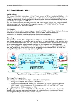
  • 1. ETTI. Lab: MPLS VPN (V2.2) Octavian Catrina, 2014 1 MPLS-based Layer 3 VPNs Overall objective The purpose of this lab is to study Layer 3 Virtual Private Networks (L3VPNs) created using MPLS and BGP. A VPN is an extension of a private network that uses a public communication infrastructure (operated by a network service provider) to interconnect a group of geographically distributed private sites. A Layer 3 VPN provides IP connectivty between VPN sites. The most common approach uses BGP to exchange VPN routes between provider edge routers and MPLS label switched paths for data transport. This approach, described in RFC 4364, "BGP/MPLS IP Virtual Private Networks" (2006), is studied in this lab. Prerequisites You should be familiar with the basic concepts and operation of MPLS and LDP (Label Distribution Protocol), intra-domain and inter-domain routing using RIPv2 and BGP, as well as MPLS-based VPNs. These topics are presented in the course material. Review them before the lab. Case study We consider the scenario shown in Figure 1. A network service provider (SP) operates an MPLS network and offers VPN services. The current task is to set up VPNs for the customers A and B. The network of each of these customers consists of two sites. The customers use private IP address space (partially overlapping). In this example, the routers in the SP network run RIPv2 for intra-domain routing, MPLS for packet forwarding, and LDP for label distribution. For the VPN service, the SP uses the approach based on MPLS and BGP defined in RFC 4364 (summarized in the next section). Customer edge routers exchange VPN routing information with the provider edge routers using RIPv2. Figure 1. Network configuration for experiments with MPLS-based VPNs. Summary of learning objectives You will set up the network shown in Figure 1 and study the following topics:  Configuration of MPLS, LDP and RIPv2 in the SP network.  Configuration of MPLS-based L3VPNs using: VRFs (Virtual Routing and Forwarding), MP-BGP (Multi-Protocol BGP), redistribution of VPN routes between MP-BGP and RIPv2 in VRFs, etc.  Operation of the MPLS network and the VPNs. During the experiments carried out in the lab, you will see how these protocols work and cooperate to achieve the VPN service, by examining the status of the routers using Cisco IOS commands and by inspecting the exchanged packets using a protocol analyzer.
  • 2. ETTI. Lab: MPLS VPN (V2.2) Octavian Catrina, 2014 2 Overview of Layer-3 MPLS-based VPNs Virtual Routing and Forwarding (VRF) PE routers have to support multiple VPN customers and to provide logically separated routing for each VPN in order to prevent acess to a VPN from other networks. The MPLS-based VPNs defined in RFC 4364 achieve this separation using a Virtual Routing/Forwarding (VRF) instance for each VPN customer. Conceptually, VRFs are separate virtual router instances running on the same physical router (Figure 2). Each VRF has its own:  VPN-specific IP routing and forwarding table.  Set of interfaces associated to the forwarding table.  Set of rules that control the import/export of routes to/from the VPN-specific routing table.  Set of routing protocol peers that populate with routes the VPN-specific routing table. Moreover, VRFs also provide the means to deal with VPNs that use overlapping blocks of IP addresses. This occurs frequently in practice, due to the widespread use of private IP address space in private networks. For example, both private networks shown in Figure 1 use 172.16.0.0/30 and 172.16.0.4/30). Figure 2. VRF instances in PE routers provide separation of VPN routing. The VRFs use two mechanisms in order to handle overlapping addresses and route import/export policies:  Route distinguisher (RD): 64-bit identifier assigned to a VPN in order to distinguish its routes in case of overlapping address spaces.  Route target (RT): 64-bit identifiers used to specify route import/export policies. The RTs are exchanged as MP-BGP extended community attributes. The high order 16 bits contain the MP- BGP extended community type and the remaining 48 bits are specified as a pair of values with the syntax 16-bit : 32-bit or 32-bit : 16-bit. We use the first variant, where the 16-bit value is the AS number, as shown in the table below. We assume that the AS number of the SP network is ASN = 1. RD values are similar. VRF/VPN RD Import RT Export RT vpn_a 1:1 1:1 1:1 vpn_b 1:2 1:2 1:2 By combining a VPN RD and a VPN route prefix we obtain a unique route prefix that can be handled by the MP-BGP routing protocol. We'll refer to this addressing scheme as the VPNv4 address family. Control plane operation Figure 3 is a high level view of the end-to-end propagation of VPN routes, taking as example the VPN routes for destination VPN A, Site 1. Figure 4 provides more details about propagation of VPN routes as well as the distribution of MPLS labels using LDP. The propagation of the VPN routes is summarized below: 1. An IP route to a VPN site is first exchanged using an IGP between a CE router and the associated VRF in a PE router. We use RIPv2. CE1A advertises to VRF vpn_a in PE1 a route to Site 1 of VPN A, with prefix 172.16.1.0/24. This route is inserted in the routing table of VRF vpn_a. 2. The VRF adds the RD assigned to the VPN and then redistributes the resulting VPNv4 route into MP-BGP (Multi-Protocol BGP), together with the VPN Label and the exported RT.
  • 3. ETTI. Lab: MPLS VPN (V2.2) Octavian Catrina, 2014 3 3. MP-BGP is responsible for the exchange of VPN routes between the PE routers. PE1 advertises the VPNv4 route to PE2 using MP-iBGP and Next-Hop itself. VPN-specific information is carried in MP- BGP attributes (VPNv4 prefix, VPN label, RT). 4. VRF vpn_a at PE2 imports the route, since the local import RT matches the RT in the route. The IPv4 route is inserted in its routing table, with PE1 as next hop. The VPN Label (LA) is also recorded. 5. VRF vpn_a at PE2 advertises the IPv4 route to router CE2A using an IGP (RIPv2). This completes the distribution of the route to 172.16.1.0/24 (Site 1 of VPN A). Figure 3. End-to-end route propagation. Observe that the VPN routes are processed only by the PE routers. The other routers in the SP network need not know anything about VPN addresses and routes. In particular, the IGP running within the SP network is not involved in VPN route propagation (it supports the VPN only by providing internal routes needed to set up LSPs between PE routers). We use RIPv2 in the SP network. Figure 4. Control plane: Route and label propagation. Data plane operation Figure 5 shows the packet forwarding for VPN A, from Site 1 to Site 2, after the final configuration of the MPLS-based VPNs. The MPLS packets carry a label stack consisting of two labels:  The top label (L1, L2) corresponds to the LSP between PE1 and PE2 set up automatically by LDP.  The bottom label (LA) is the VPN label assigned to the VPN by the egress router (in this example, the label assigned to VPN A by PE2). This label allows the egress router to demultiplex the packet flow received on the LSP, indentifying the packets belonging to each VPN. Figure 5 shows that P1 pops the top label, instead of PE1. This procedure is called penultimate hop popping (PHP), i.e., an LSP label is removed by the penultimate router, rather than the last router, and was requested by PE1 during label distribution (Implicit-Null label). This avoids an unnecessary label lookup at PE1, and it is the default behavior of Cisco routers.
  • 4. ETTI. Lab: MPLS VPN (V2.2) Octavian Catrina, 2014 4 Figure 5. Packet forwarding in MPLS-based VPN. 1. Network setup The experiments are carried out using the network shown in Figure 1. The SP network consists of the edge routers PE1 and PE2 and the internal routers P1 and P2. The SP network interconnects two sites of Customer A (edge routers CE1A and CE2A) and two sites of Customer B (edge routers CE1B and CE2B). All routers run Cisco IOS and are configured with Fast Ethernet interfaces. Your task is to set up for each customer a VPN that interconnects its two sites. The instructions given in the following assume that the experiments are carried out using the network emulator GNS3. 1.1. Load the initial GNS project. You start with a GNS project that contains the network shown in Figure 1. The IP addresses are already configured, except for the VRF interfaces. Check the initial configuration of the routers. 1.2. Start the routers and check the CPU load. Start a router using GNS (right-click on the router and select Start) and then check the CPU load (on Windows, start the Task Manager and select the Performance tab). Wait until the router boots up. If the CPU load does not decrease to a low level, adjust the Idle PC parameter (right-click on the router and select Idle-PC); ask the instructor if necessary. Then start the entire network and check that the CPU load falls to a low level once all the routers boot up. 1.3. Start router consoles. Start consoles for all the routers using GNS (Console button in the toolbar). Each console should show the Cisco CLI prompt router-name# for the privileged mode, which allows you to enter any command for configuring the router or examining its status. You have to carry out a quite lengthy, incremental configuration. To make this process faster and less error prone, use the following procedure:  At each step, edit using a text editor the batches of commands for all the routers you configure and then copy each batch from the text editor to the router's console window (right-click).  Before proceeding to the next step, verify if the router configuration and operation are correct, save the configuration using the IOS command "copy run start" or "write" and then save the GNS project. 2. Configure interior routing in the SP network We start by setting up our SP network, and afterwards we'll create the VPNs for our clients. The IP addresses should already be configured now, so we can proceed to configure interior routing. We use for this purpose RIPv2. 2.1. Configure RIPv2 for interior routing in the SP network (routers PE1, PE2, P1, and P2). The configuration commands for PE1 are listed below (starting in global configuration mode). The configuration of the other routers is similar.
  • 5. ETTI. Lab: MPLS VPN (V2.2) Octavian Catrina, 2014 5 router rip version 2 network 10.0.0.0 Begin RIP configuration (and start RIP). Set RIP version 2. Enable RIP on interfaces connected to 10.0.0.0/8. 2.2. Test and troubleshoot internal routing in the SP network. - Examine the status of the SP routers using the commands show ip protocols and show ip route. Does the router receive information from all its neighbors in the SP network? Do you see routes to all destinations in the SP network (all links and the loopback interfaces)? - Test the connectivity between PE1 and PE2 using ping. 2.3. Save the configuration of the routers and the GNS project. 3. Configure MPLS in the SP network We're now going to configure MPLS in the SP network and examine using the protocol analyzer the packets exchanged by LDP to set up adjacencies and distribute labels. 3.1. Capture the traffic on interface f2/0 of PE1 (link between PE1 and P1). 3.2. Configure MPLS and LDP in the SP network (routers PE1, PE2, P1, and P2). Enable MPLS for all interfaces connected to the SP network (but not on the interfaces connected to the client networks). You should also have CEF (Cisco Express Forwarding) enabled for each SP router. The configuration commands for PE1 are listed below (similar for the others): ip cef mpls label protocol ldp mpls ldp router-id Loopback0 interface f2/0 mpls ip Enable CEF Set LDP for MPLS label distribution. Configure the LDP Router-ID Activate MPLS on interface f0/0 3.3. Check if MPLS and LDP are working properly. For the current (default) configuration, LDP works as follows:  The router assigns labels to prefix-based FECs (destination prefixes found in the routing table), using per-platform label space.  Then the router sends its own label bindings to its LDP-enabled neighbors, using independent, downstream unsolicited label distribution. - Examine the status of the LDP sessions established by the router with its neighbors: show mpls ldp neighbor Has the router successfully established LDP sessions (Open state) with all its neighbors? - Examine the router's Label Information Base (LIB): show mpls ldp bindings Note that Cisco IOS uses here the term "tag" instead of "label" (hence tsr = LSR, tib = LIB). Compare the information in the LIB with the routing table. Do you see label bindings for all (applicable) destinations? Do you see, for each destination, a local binding as well as remote bindings from all LDP neighbors? What label retention policy is being used? - Examine the router's MPLS forwarding table, also called Forwarding Information Base (FIB): show mpls forwarding-table
  • 6. ETTI. Lab: MPLS VPN (V2.2) Octavian Catrina, 2014 6 The FIB is built based on the routing table and the LIB, and is used for MPLS packet forwarding. LSPs are (implicitly) defined by matching FIB entries along the path to a destination prefix. Figure out how the FIB is built and used by comparing the information in the FIB entries with the routing table and the LIB. - Test the connectivity between PE1 and PE2 using ping (try the addresses of the loopback interfaces). 3.4. Examine the exchanged messages using the protocol analyzer. Start the Wireshark protocol analyzer (from GNS3) in order to examine the packets captured after enabling MPLS and LDP. - In Wireshark, set ldp as filter expression, in order to display the LDP messages. Examine the messages exchanged by PE1 and P1 during the LDP session setup. Compare the label bindings in the LDP messages with the information displayed by the command show mpls ldp bindings. - In Wireshark, set icmp as filter expression, in order to display the ICMP messages exchanged during the test. Do you see MPLS headers for all ICMP messages? If not, why? (Hint: The routers apply by default Penultimate Hop Popping.) 3.5. Save the configuration of the routers and the GNS project. 4. Configure RIPv2 on the customer edge (CE) routers We can now begin the configuration of the VPNs for our two customers. We start by completing the configuration of the CE routers. The interfaces should already be configured, so we can proceed to the configuration of RIPv2. 4.1. Configure and start RIPv2 on the routers CE1A, CE2A, CE1B, and CE2B. The configuration commands for CE1A are listed below (similar for the others, don't forget 172.17.0.0). router rip version 2 network 172.16.0.0 no auto-summary Begin RIP configuration. Set RIP version 2. Enable RIP on interfaces connected to 172.16.0.0/16. Disable route summarization. 4.2. Check if RIPv2 is working properly. Examine the current status using the commands show ip protocols and show ip route. 4.3. Save the configuration of the routers and the GNS project. 5. Create the VRFs and configure their interfaces 5.1. Create the VRFs associated to the VPNs on PE1 and PE2. A VRF is identified by a name (unique within a physical router). We call vpn_a and vpn_b the VRFs for VPN A and VPN B, respectively. The configuration commands for PE1 are listed below (similar for PE2). ip vrf vpn_a rd 1:1 route-target export 1:1 route-target import 1:1 ip vrf vpn_b rd 1:2 route-target export 1:2 Configure the VRF vpn_a Set the route distinguisher to 1:1. Set the imported and exported route target to 1:1. Configure the VRF vpn_b Set the route distinguisher to 1:2. Set the imported and exported route target to 1:2.
  • 7. ETTI. Lab: MPLS VPN (V2.2) Octavian Catrina, 2014 7 route-target import 1:2 5.2. Configure the VRF interfaces on PE1 and PE2. The configuration commands for PE1 are listed below (similar for PE2). interface FastEthernet0/0 ip vrf forwarding vpn_a ip address 172.16.0.1 255.255.255.252 no shutdown interface FastEthernet1/0 ip vrf forwarding vpn_b ip address 172.16.0.1 255.255.255.252 no shutdown Configure the interface f0/0 . Associate the interface with VRF vpn_a. Assign the IP address and subnet mask to the interface. Turn on the interface. Configure the interface f1/0. Associate the interface with VRF vpn_b. Assign the IP address and subnet mask to the interface. Turn on the interface. 5.3. Examine the initial VRF configuration and status on PE1 and PE2. show ip vrf show ip vrf detail show ip vrf interfaces show ip route show ip route vrf vpn_a show ip route vrf vpn_b Status/configuration of the VRFs, summary and details. Status/configuration of the VRF interfaces. Global routing table. VRF routing table for VRF vpn_a. VRF routing table for VRF vpn_b. Is everything configured and working correctly? 5.4. Analysis of the address configuration. According to the address assignment in Figure 1, at step 5.1 you configured the same address for the interfaces f0/0 and f1/0 of router PE1. Can the network operate correctly with this configuration? Why? Furthermore, Figure 1 shows that you have to configure the address 172.16.0.5 to the interfaces f0/0 and f1/0 of router PE2. Could we have assigned the same addresses as for PE1? Why? 5.5. Save the configuration of the routers and the GNS project. 6. Configure RIPv2 on the VRFs 6.1. Configure RIPv2 to exchange routes between each CE router and the associated VRF instance. The configuration commands for the PE1 VRFs are listed below (similar on PE2). To configure RIPv2 routing for IPv4 on a VRF instance, you have to use the command address-family ipv4 vrf. router rip address-family ipv4 vrf vpn_a network 172.16.0.0 no auto-summary exit-address-family address-family ipv4 vrf vpn_b network 172.16.0.0 no auto-summary exit-address-family Begin (resume) RIPv2 configuration. Run RIP for VRF vpn_a, on interfaces connected to the (IPv4) prefix 172.16.0.0/16. Run RIP for VRF vpn_b, on interfaces connected to the (IPv4) prefix 172.16.0.0/16 (the address spaces used by the two customers overlap). 6.2. Examine the current configuration and status of the VRFs on PE1 and PE2.
  • 8. ETTI. Lab: MPLS VPN (V2.2) Octavian Catrina, 2014 8 show ip vrf show ip vrf detail show ip vrf interfaces show ip route show ip route vrf vpn_a show ip route vrf vpn_b Status/configuration of the VRFs, summary and details. Status/configuration of the VRF interfaces. Global routing table. VRF routing table for VRF vpn_a. VRF routing table for VRF vpn_b. Recall that on PE routers we have 3 separate routing tables (2 VRF tables and a global table). Is everything working correctly? Do you see now all the routes? 6.3. Examine the current status of the CE routers. Examine the routing tables of the CE routers (show ip route). Test the connectivity between CE routers and PE routers using ping. 6.4. Save the configuration of the routers (PE1, PE2) and the GNS project. 7. Configure MP-BGP on PE routers The VPN routes will be propagated between PE routers using MP-BGP. We'll configure this in several steps. 7.1. Configure and start BGP on PE1 and PE2. Start BGP on PE1 and PE2 and establish a BGP connection between them. The AS number (ASN) of the SP network is ASN = 1. The configuration commands for PE1 (10.100.255.1) are listed below (symmetric configuration for PE2). router bgp 1 network 10.100.255.1 mask 255.255.255.255 neighbor 10.100.255.4 remote-as 1 neighbor 10.100.255.4 update-source Loopback0 no synchronization no auto-summary Begin BGP configuration for the AS with ASN = 1. Advertise BGP routes to the prefix 10.100.255.1/32. Establish a BGP connection to 10.100.255.4 (PE1) in AS 1 (iBGP), using as source address the address of the interface Loopback0. 7.2. Configure MP-BGP for VPNs on PE1 and PE2. The configuration commands for PE1 are listed below (symmetric configuration for PE2). router bgp 1 address-family vpnv4 neighbor 10.100.255.4 activate neighbor 10.100.255.4 send-community extended neighbor 10.100.255.4 next-hop-self Begin (resume) BGP configuration for AS 1. Begin configuration for the address family vpnv4. For the BGP connection to 10.100.255.4: advertise vpnv4 routes; send Extended Community attributes (for RT); set the Next-Hop attribute of the routes to PE1's own address. 7.3. Examine the current BGP configuration and status. sh ip bgp summary sh ip bgp all sh ip route sh ip bgp neighbors
  • 9. ETTI. Lab: MPLS VPN (V2.2) Octavian Catrina, 2014 9 Is there a BGP session between PE1 and PE2? Do you see all the routes you expected in the routing tables? Why is it necessary to ask MP-BGP to set the Next-Hop attribute of the advertised VPN routes to the sender's own address (next-hop-self)? How will this affect VPN traffic forwarding in the SP network? 7.4. Save the configuration of the routers (PE1, PE2) and the GNS project. 8. Configure route redistribution between RIPv2 and MP-BGP We need to redistribute the VPN routes between RIPv2 and BGP in the VRFs, in order to enable the propagation of the VPN routes between the CE routers, via the PE routers. 8.1. Configure RIP to redistribute BGP routes, on PE1 and PE2. The configuration commands for PE1 are listed below (similar for PE2): router rip address-family ipv4 vrf vpn_a redistribute bgp 1 metric transparent exit-address-family address-family ipv4 vrf vpn_b redistribute bgp 1 metric transparent Begin (resume) RIPv2 configuration. Begin configuration for address family ipv4 for VRF vpn_a. Redistribute BGP routes (for AS 1) into RIP, preserving the RIP metric. Similar for VRF vpn_b. 8.2. Configure BGP to redistribute RIP routes, for the VRFs created in PE1 and PE2. The configuration commands for PE1 are listed below (same commands for PE2): router bgp 1 address-family ipv4 vrf vpn_a redistribute rip no auto-summary no synchronization exit-address-family address-family ipv4 vrf vpn_b redistribute rip no auto-summary no synchronization Begin (resume) BGP configuration for AS 1. Begin configuration for address family ipv4 for VRF vpn_a. Redistribute RIP routes from VRF vpn_a into BGP. Similar for VRF vpn_b. 8.3. Examine the current BGP configuration and status. sh ip bgp summary sh ip bgp all sh ip route sh ip route vrf vpn_a sh ip route vrf vpn_b You should find now all the VPN routes in the BGP routing tables of PE1 and PE2. Do you also see all the VPN routes in the PE/VRF and CE routing tables? 8.4. Save the configuration of the routers (PE1, PE2) and the GNS project.
  • 10. ETTI. Lab: MPLS VPN (V2.2) Octavian Catrina, 2014 10 9. VPN operation (data and control planes) At this point, we completed the VPN configuration. The VPN routes should be present in the routing tables of the VRFs and of the CE routers. 9.1. Test the connectivity between the two sites of the same VPN. Use ping, e.g., from CE1A to CE2A: ping 172.16.2.1 source 172.16.1.1 repeat 10 9.2. Examine the data plane operation using the protocol analyzer. Capture the traffic at the interface f1/0 of P1 (link between P1 and P2) using GNS3. Generate data traffic between the VPN sites using ping. Examine the exchanged packets using Wireshark (filter icmp). Compare the MPLS headers with the contents of the Label Information Base (show mpls ldp bindings) and Forwarding Information Base (show mpls forwarding-table) of P1 and P2. 9.3. Examine the control plane operation using the protocol analyzer. Capture the traffic at the interface f1/0 of P1 (link between P1 and P2) using GNS3. - Turn off the interface f0/0 of CE1A (shutdown). Examine the exchanged BGP packets using Wireshark (filter bgp). What is the effect of turning off this interface on the VPNs? How does BGP learn about this event? How does BGP react to the event? - Turn on the interface f0/0 of CE1A (no shutdown). Examine the exchanged BGP packets using Wireshark (filter bgp). Same questions as above. 10. Optional 10.1. Is it possible to transfer IP packets between a site of VPN A and a site of VPN B with the current configuration? Why? 10.2. Modify the configuration of the routers PE1 and PE2 such that: (a) Site 1 of VPN A can communicate with the other site of VPN A as well as with Site 1 of VPN B. (b) Site 2 of VPN A can only communicate with Site 1 of VPN A. (c) Site 2 of VPN B can only communicate with Site 1 of VPN B.