Downloaded 15 times

![Mode 1’s Operation
18
THx TLx
0 0 0 1 0 0 0 0 0 1 0 1 1 0 0 1
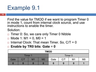
THx and TLx store start value
Timer operation always count-up (increase) on [THx, TLX] each machine cycle
SETB TRx instruction to start running timer
Over flow when Increase FFFF to 0000
Interval value = FFFF – [TH,TL]
FFFF give minimum interval time
0000 give maximum interval time
Example:
MOV TH0, #22H
MOV TL0, #00H
; Then interval is FFFF – 2200 = DDFF Machine Cycle.
Tips: Monitor TFx with instruction
“MonitorLable : JNB TFx, MonitorLable”](https://image.slidesharecdn.com/timers08-160523171853/85/Microprocessor-Week-9-Timer-and-Counter-18-320.jpg)
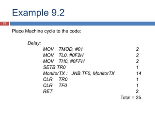
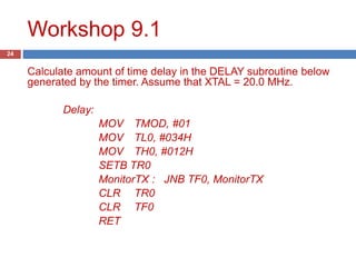
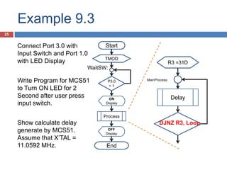
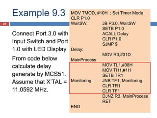
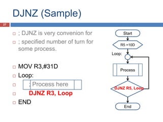
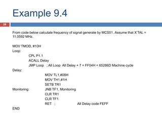
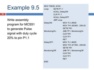
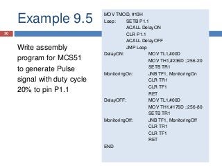

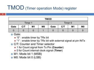
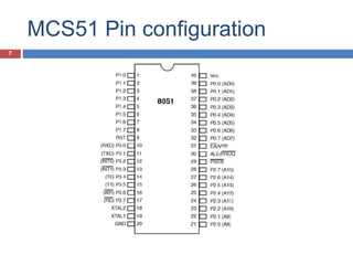
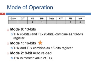
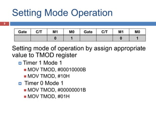
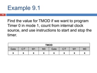
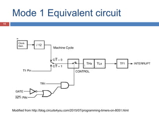
The document discusses timers and counters on the MCS-51 microcontroller. It describes the timer registers TMOD, TCON, THx and TLx. It explains the four modes of the timers and how to set the mode using the TMOD register. Examples are provided to calculate delays generated by timers based on settings of the THx and TLx registers. Programming techniques like DJNZ are also demonstrated for repeated timing loops.