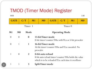
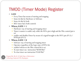
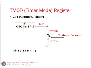
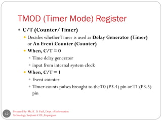
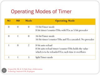
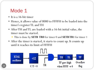
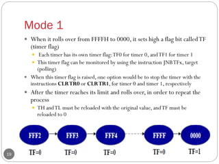
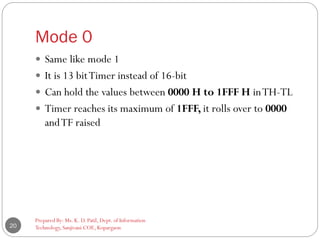
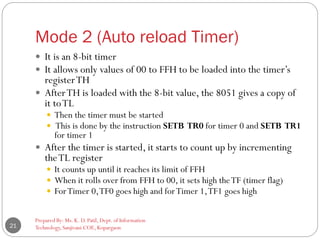
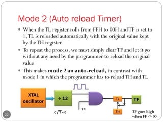
1
Unit 5: 8051 Timers/Counters Programming
(Part 1)
Subject: Processor Architecture & Interfacing
(SPPU, Pune 2015 Course of Information Technology)
Class: SEIT Semester: II
Prepared By,
Ms. K. D. Patil, Assistant Professor
Department of Information Technology
(NBA accredited)
Sanjivani College of Engineering, Kopargaon-423603.
Maharashtra, India.
(An Autonomous Institute, Affiliated with SPPU, Pune.)
NAAC ‘A’ Grade Accredited, ISO 9001:2015 certified
Contents
Prepared By: Ms. K. D. Patil, Dept. of Information
Technology, Sanjivani COE, Kopargaon2
 Part 1
 Introduction
 Special Function Registers
 Timer 0 Register
 Timer 1 Register
 TMOD Register
 TCON Register
 How to UseTimer
 Operating Modes ofTimer
 Part 2
 Timer Programming
 Mode 1 Programming
 Mode 2 Programming
 Introduction to Counters
 Counter Programming
Learning Outcomes
Prepared By: Ms. K. D. Patil, Dept. of Information
Technology, Sanjivani COE, Kopargaon3
 Student will be able to
 IntroduceTimers/Counters of 8051 microcontroller
 Operating modes of 8051Timers
 Special Function Registers and configurations of 8051
Timers/Counters
 Apply knowledge of 8051 assembly language to write a code for
8051Timer
Introduction to Timers
Prepared By: Ms. K. D. Patil, Dept. of Information
Technology, Sanjivani COE, Kopargaon4
 The 8051 has two timers/counters.
 Timer 0
 Timer 1
 They can be used
 as Timers to generate a time delay or
 as Event counters to count events happening outside the
microcontroller
 BothTimer 0 andTimer 1 are 16 bits wide
 Since 8051 has an 8-bit architecture, each 16-bits timer is
accessed as two separate registers of low byte and high byte
Special Function Registers of Timers
Prepared By: Ms. K. D. Patil, Dept. of Information
Technology, Sanjivani COE, Kopargaon5
 Timer 0 Register
 Timer 1 Register
 TMOD Register
 TCON Register
Timer 0 Register
6
 The 16 bit register ofTimer 0 is accessed as low byte and
high byte.
 Low byte register is called asTL0 (Timer 0 low Byte)
 High byte register is called asTH0 (Timer 0 High Byte)
 Can be assessed and read as any register
 Example:
MOVTL0,#4FH ; moves value 4F intoTL0
MOV R5,TH0 ; savesTH0 into R5
TH0 TL0
D15 D14 D13 D12 D11 D10 D9 D8 D7 D6 D5 D4 D3 D2 D1 D0
Timer 1 Register
Prepared By: Ms. K. D. Patil, Dept. of Information
Technology, Sanjivani COE, Kopargaon7
 The 16 bit register ofTimer 1 is accessed as low byte and
high byte.
 Low byte register is called asTL1 (Timer 1 low Byte)
 High byte register is called asTH1 (Timer 1 High Byte)
 Can be assessed and read as any register
TH1 TL1
D15 D14 D13 D12 D11 D10 D9 D8 D7 D6 D5 D4 D3 D2 D1 D0
TMOD (Timer Mode) Register
Prepared By: Ms. K. D. Patil, Dept. of Information
Technology, Sanjivani COE, Kopargaon8
 Byte addressable
 Both timers 0 and 1 use the same register, called
TMOD (timer mode) to set the various timer
operation modes
 It is a 8-bit register
 The lower 4 bits are forTimer 0
 The upper 4 bits are forTimer 1
 In each case,The lower 2 bits are used to set the timer mode
 The upper 2 bits to specify the operation
TMOD (Timer Mode) Register
Prepared By: Ms. K. D. Patil, Dept. of Information
Technology, Sanjivani COE, Kopargaon9
GATE C/T M1 M0 GATE C/T M1 M0
Timer 1 Timer 0
M1 M0 Mode Operating Mode
0 0 0 13-bitTimer mode
8-bit timer/counterTHx withTLx as 5-bit prescaler
0 1 1 16-bitTimer mode
16-bit timer/counterTHx andTLx cascaded. No
prescaler
1 0 2 8-bit auto reload
8-bit auto reload timer/counterTHx holds the value
which is to be reloadedTLx each time it overflows
1 1 3 SplitTimer mode
MSB LSB
TMOD (Timer Mode) Register
Prepared By: Ms. K. D. Patil, Dept. of Information
Technology, Sanjivani COE, Kopargaon10
 GATE
 EveryTimer has means of starting and stopping
 Some do this by Hardware or Software
 Some do this by both
 8051 timer have both controls
 When, GATE = 1
 Hardware way of starting and stopping timer
 Timer/counter is enable only while the INTx pin is high and theTRx control pin is
set
 enables and disablesTimer by means of a signal brought to the INT1 pin (P3.3) /
INT0 pin (P3.2)
 When, GATE = 0
 Software way of starting and stopping timer
 Operates regardless of the logic state of INTx bit
 enabled whenever theTRx control bit is set
 To start timer use instruction “SETBTRx”
 To clear timer use instruction “CLRTRx”
TMOD (Timer Mode) Register
Prepared By: Ms. K. D. Patil, Dept. of Information
Technology, Sanjivani COE, Kopargaon11
 C/T (Counter/Timer)
OSC 1/12
PinTx (P3.4/P3.5)
f f/12
C/T=0
C/T=1
To timer /counter
TMOD (Timer Mode) Register
Prepared By: Ms. K. D. Patil, Dept. of Information
Technology, Sanjivani COE, Kopargaon12
 C/T (Counter/Timer)
 Decides whetherTimer is used as Delay Generator (Timer)
or An Event Counter (Counter)
 When, C/T = 0
 Time delay generator
 input from internal system clock
 When, C/T = 1
 Event counter
 Timer counts pulses brought to theT0 (P3.4) pin orT1 (P3.5)
pin
TCON (Timer Control) Register
 Bit addressable
 8 - bit register
 Upper 4 bits are used to storeTF andTR bits of both timersTimer
0 andTimer 1
 The lower 4 bits are reserved for controlling the interrupts bits
Prepared By: Ms. K. D. Patil, Dept. of Information
Technology, Sanjivani COE, Kopargaon13
TF1 TR1 TF0 TR0 IE1 IT1 IE0 IT0
T1 T0 INT 1 INT 0
MSB LSB
TCON (Timer Control) Register
14
TCON Bit Function
TF1 TCON.7 Timer 1 Overflow Flag. set by hardware whenT/C 1 overflows.
Cleared by hardware
TR1 TCON.6 Timer 1 run control Bit. Set or cleared by software to turn
timer on/off
TF0 TCON.5 Timer 0 Overflow Flag. set by hardware whenT/C 0 overflows.
Cleared by hardware
TR0 TCON.4 Timer 0 run control Bit. Set or cleared by software to turn
timer on/off
IE1
IE0
TCON.3
TCON.1
Keep track of edge-triggered interrupt only
External Interrupt 1 edge flag bit (High to Low)
External Interrupt 0 edge flag bit (High to Low)
IT1
IT0
TCON.2
TCON.0
Set/cleared by software to specify falling edge/low level triggered
interrupt
Interrupt 1 type control bit (Low to High)
Interrupt 0 type control bit (Low to High)
Equivalent Instructions for TCON
15
ForTimer 0
SETB TR0 SETB TCON.4
CLR TR0 CLR TCON.4
SETB TF0 SETB TCON.5
CLR TF0 CLR TCON.5
ForTimer 1
SETB TR1 SETB TCON.6
CLR TR1 CLR TCON.6
SETB TF1 SETB TCON.7
CLR TF1 CLR TCON.7
How to Use Timer 0?
Prepared By: Ms. K. D. Patil, Dept. of Information
Technology, Sanjivani COE, Kopargaon16
Operating Modes of Timer
Prepared By: Ms. K. D. Patil, Dept. of Information
Technology, Sanjivani COE, Kopargaon17
M1 M0 Mode Operating Mode
0 0 0 13-bitTimer mode
8-bit timer/counterTHx withTLx as 5-bit prescaler
0 1 0 16-bitTimer mode
16-bit timer/counterTHx andTLx cascaded. No prescaler
1 0 2 8-bit auto reload
8-bit auto reload timer/counterTHx holds the value
which is to be reloadedTLx each time it overflows
1 1 3 SplitTimer mode
Mode 1
Prepared By: Ms. K. D. Patil, Dept. of Information
Technology, Sanjivani COE, Kopargaon18
 It is a 16-bit timer
 Hence, it allows value of 0000 to FFFFH to be loaded into the
timer’s registerTL andTH
 AfterTH andTL are loaded with a 16-bit initial value, the
timer must be started.
 This is done by SETB TR0 for timer 0 and SETBTR1 for timer 1
 After the timer is started, it starts to count up. It counts up
until it reaches its limit of FFFFH
Mode 1
Prepared By: Ms. K. D. Patil, Dept. of Information
Technology, Sanjivani COE, Kopargaon19
 When it rolls over from FFFFH to 0000, it sets high a flag bit calledTF
(timer flag)
 Each timer has its own timer flag:TF0 for timer 0, andTF1 for timer 1
 This timer flag can be monitored by using the instruction JNBTFx, target
(polling)
 When this timer flag is raised, one option would be to stop the timer with the
instructions CLRTR0 or CLRTR1, for timer 0 and timer 1, respectively
 After the timer reaches its limit and rolls over, in order to repeat the
process
 TH andTL must be reloaded with the original value, andTF must be
reloaded to 0
Mode 0
Prepared By: Ms. K. D. Patil, Dept. of Information
Technology, Sanjivani COE, Kopargaon20
 Same like mode 1
 It is 13 bitTimer instead of 16-bit
 Can hold the values between 0000 H to 1FFF H inTH-TL
 Timer reaches its maximum of 1FFF, it rolls over to 0000
andTF raised
Mode 2 (Auto reload Timer)
Prepared By: Ms. K. D. Patil, Dept. of Information
Technology, Sanjivani COE, Kopargaon21
 It is an 8-bit timer
 It allows only values of 00 to FFH to be loaded into the timer’s
registerTH
 AfterTH is loaded with the 8-bit value, the 8051 gives a copy of
it toTL
 Then the timer must be started
 This is done by the instruction SETB TR0 for timer 0 and SETB TR1
for timer 1
 After the timer is started, it starts to count up by incrementing
theTL register
 It counts up until it reaches its limit of FFH
 When it rolls over from FFH to 00, it sets high theTF (timer flag)
 ForTimer 0,TF0 goes high and forTimer 1,TF1 goes high
Mode 2 (Auto reload Timer)
Prepared By: Ms. K. D. Patil, Dept. of Information
Technology, Sanjivani COE, Kopargaon22
 When theTL register rolls from FFH to 00H andTF is set to
1,TL is reloaded automatically with the original value kept
by theTH register
 To repeat the process, we must simply clearTF and let it go
without any need by the programmer to reload the original
value
 This makes mode 2 an auto-reload, in contrast with
mode 1 in which the programmer has to reloadTH andTL
TF goes high
when FF -> 00
Reference
Prepared By: Ms. K. D. Patil, Dept. of Information
Technology, Sanjivani COE, Kopargaon23
 “The 8051 Microcontroller and Embedded Systems using
Assembly and C” , Muhammad Ali Mazidi, Janice Gillispie
Mazidi, Rolin D. McKinlay, Second Edition, Pearson
publication
Prepared By: Ms. K. D. Patil, Dept. of Information
Technology, Sanjivani COE, Kopargaon24

SE PAI Unit 5_Timer Programming in 8051 microcontroller_Part 1

  • 1.
    1 Unit 5: 8051Timers/Counters Programming (Part 1) Subject: Processor Architecture & Interfacing (SPPU, Pune 2015 Course of Information Technology) Class: SEIT Semester: II Prepared By, Ms. K. D. Patil, Assistant Professor Department of Information Technology (NBA accredited) Sanjivani College of Engineering, Kopargaon-423603. Maharashtra, India. (An Autonomous Institute, Affiliated with SPPU, Pune.) NAAC ‘A’ Grade Accredited, ISO 9001:2015 certified
  • 2.
    Contents Prepared By: Ms.K. D. Patil, Dept. of Information Technology, Sanjivani COE, Kopargaon2  Part 1  Introduction  Special Function Registers  Timer 0 Register  Timer 1 Register  TMOD Register  TCON Register  How to UseTimer  Operating Modes ofTimer  Part 2  Timer Programming  Mode 1 Programming  Mode 2 Programming  Introduction to Counters  Counter Programming
  • 3.
    Learning Outcomes Prepared By:Ms. K. D. Patil, Dept. of Information Technology, Sanjivani COE, Kopargaon3  Student will be able to  IntroduceTimers/Counters of 8051 microcontroller  Operating modes of 8051Timers  Special Function Registers and configurations of 8051 Timers/Counters  Apply knowledge of 8051 assembly language to write a code for 8051Timer
  • 4.
    Introduction to Timers PreparedBy: Ms. K. D. Patil, Dept. of Information Technology, Sanjivani COE, Kopargaon4  The 8051 has two timers/counters.  Timer 0  Timer 1  They can be used  as Timers to generate a time delay or  as Event counters to count events happening outside the microcontroller  BothTimer 0 andTimer 1 are 16 bits wide  Since 8051 has an 8-bit architecture, each 16-bits timer is accessed as two separate registers of low byte and high byte
  • 5.
    Special Function Registersof Timers Prepared By: Ms. K. D. Patil, Dept. of Information Technology, Sanjivani COE, Kopargaon5  Timer 0 Register  Timer 1 Register  TMOD Register  TCON Register
  • 6.
    Timer 0 Register 6 The 16 bit register ofTimer 0 is accessed as low byte and high byte.  Low byte register is called asTL0 (Timer 0 low Byte)  High byte register is called asTH0 (Timer 0 High Byte)  Can be assessed and read as any register  Example: MOVTL0,#4FH ; moves value 4F intoTL0 MOV R5,TH0 ; savesTH0 into R5 TH0 TL0 D15 D14 D13 D12 D11 D10 D9 D8 D7 D6 D5 D4 D3 D2 D1 D0
  • 7.
    Timer 1 Register PreparedBy: Ms. K. D. Patil, Dept. of Information Technology, Sanjivani COE, Kopargaon7  The 16 bit register ofTimer 1 is accessed as low byte and high byte.  Low byte register is called asTL1 (Timer 1 low Byte)  High byte register is called asTH1 (Timer 1 High Byte)  Can be assessed and read as any register TH1 TL1 D15 D14 D13 D12 D11 D10 D9 D8 D7 D6 D5 D4 D3 D2 D1 D0
  • 8.
    TMOD (Timer Mode)Register Prepared By: Ms. K. D. Patil, Dept. of Information Technology, Sanjivani COE, Kopargaon8  Byte addressable  Both timers 0 and 1 use the same register, called TMOD (timer mode) to set the various timer operation modes  It is a 8-bit register  The lower 4 bits are forTimer 0  The upper 4 bits are forTimer 1  In each case,The lower 2 bits are used to set the timer mode  The upper 2 bits to specify the operation
  • 9.
    TMOD (Timer Mode)Register Prepared By: Ms. K. D. Patil, Dept. of Information Technology, Sanjivani COE, Kopargaon9 GATE C/T M1 M0 GATE C/T M1 M0 Timer 1 Timer 0 M1 M0 Mode Operating Mode 0 0 0 13-bitTimer mode 8-bit timer/counterTHx withTLx as 5-bit prescaler 0 1 1 16-bitTimer mode 16-bit timer/counterTHx andTLx cascaded. No prescaler 1 0 2 8-bit auto reload 8-bit auto reload timer/counterTHx holds the value which is to be reloadedTLx each time it overflows 1 1 3 SplitTimer mode MSB LSB
  • 10.
    TMOD (Timer Mode)Register Prepared By: Ms. K. D. Patil, Dept. of Information Technology, Sanjivani COE, Kopargaon10  GATE  EveryTimer has means of starting and stopping  Some do this by Hardware or Software  Some do this by both  8051 timer have both controls  When, GATE = 1  Hardware way of starting and stopping timer  Timer/counter is enable only while the INTx pin is high and theTRx control pin is set  enables and disablesTimer by means of a signal brought to the INT1 pin (P3.3) / INT0 pin (P3.2)  When, GATE = 0  Software way of starting and stopping timer  Operates regardless of the logic state of INTx bit  enabled whenever theTRx control bit is set  To start timer use instruction “SETBTRx”  To clear timer use instruction “CLRTRx”
  • 11.
    TMOD (Timer Mode)Register Prepared By: Ms. K. D. Patil, Dept. of Information Technology, Sanjivani COE, Kopargaon11  C/T (Counter/Timer) OSC 1/12 PinTx (P3.4/P3.5) f f/12 C/T=0 C/T=1 To timer /counter
  • 12.
    TMOD (Timer Mode)Register Prepared By: Ms. K. D. Patil, Dept. of Information Technology, Sanjivani COE, Kopargaon12  C/T (Counter/Timer)  Decides whetherTimer is used as Delay Generator (Timer) or An Event Counter (Counter)  When, C/T = 0  Time delay generator  input from internal system clock  When, C/T = 1  Event counter  Timer counts pulses brought to theT0 (P3.4) pin orT1 (P3.5) pin
  • 13.
    TCON (Timer Control)Register  Bit addressable  8 - bit register  Upper 4 bits are used to storeTF andTR bits of both timersTimer 0 andTimer 1  The lower 4 bits are reserved for controlling the interrupts bits Prepared By: Ms. K. D. Patil, Dept. of Information Technology, Sanjivani COE, Kopargaon13 TF1 TR1 TF0 TR0 IE1 IT1 IE0 IT0 T1 T0 INT 1 INT 0 MSB LSB
  • 14.
    TCON (Timer Control)Register 14 TCON Bit Function TF1 TCON.7 Timer 1 Overflow Flag. set by hardware whenT/C 1 overflows. Cleared by hardware TR1 TCON.6 Timer 1 run control Bit. Set or cleared by software to turn timer on/off TF0 TCON.5 Timer 0 Overflow Flag. set by hardware whenT/C 0 overflows. Cleared by hardware TR0 TCON.4 Timer 0 run control Bit. Set or cleared by software to turn timer on/off IE1 IE0 TCON.3 TCON.1 Keep track of edge-triggered interrupt only External Interrupt 1 edge flag bit (High to Low) External Interrupt 0 edge flag bit (High to Low) IT1 IT0 TCON.2 TCON.0 Set/cleared by software to specify falling edge/low level triggered interrupt Interrupt 1 type control bit (Low to High) Interrupt 0 type control bit (Low to High)
  • 15.
    Equivalent Instructions forTCON 15 ForTimer 0 SETB TR0 SETB TCON.4 CLR TR0 CLR TCON.4 SETB TF0 SETB TCON.5 CLR TF0 CLR TCON.5 ForTimer 1 SETB TR1 SETB TCON.6 CLR TR1 CLR TCON.6 SETB TF1 SETB TCON.7 CLR TF1 CLR TCON.7
  • 16.
    How to UseTimer 0? Prepared By: Ms. K. D. Patil, Dept. of Information Technology, Sanjivani COE, Kopargaon16
  • 17.
    Operating Modes ofTimer Prepared By: Ms. K. D. Patil, Dept. of Information Technology, Sanjivani COE, Kopargaon17 M1 M0 Mode Operating Mode 0 0 0 13-bitTimer mode 8-bit timer/counterTHx withTLx as 5-bit prescaler 0 1 0 16-bitTimer mode 16-bit timer/counterTHx andTLx cascaded. No prescaler 1 0 2 8-bit auto reload 8-bit auto reload timer/counterTHx holds the value which is to be reloadedTLx each time it overflows 1 1 3 SplitTimer mode
  • 18.
    Mode 1 Prepared By:Ms. K. D. Patil, Dept. of Information Technology, Sanjivani COE, Kopargaon18  It is a 16-bit timer  Hence, it allows value of 0000 to FFFFH to be loaded into the timer’s registerTL andTH  AfterTH andTL are loaded with a 16-bit initial value, the timer must be started.  This is done by SETB TR0 for timer 0 and SETBTR1 for timer 1  After the timer is started, it starts to count up. It counts up until it reaches its limit of FFFFH
  • 19.
    Mode 1 Prepared By:Ms. K. D. Patil, Dept. of Information Technology, Sanjivani COE, Kopargaon19  When it rolls over from FFFFH to 0000, it sets high a flag bit calledTF (timer flag)  Each timer has its own timer flag:TF0 for timer 0, andTF1 for timer 1  This timer flag can be monitored by using the instruction JNBTFx, target (polling)  When this timer flag is raised, one option would be to stop the timer with the instructions CLRTR0 or CLRTR1, for timer 0 and timer 1, respectively  After the timer reaches its limit and rolls over, in order to repeat the process  TH andTL must be reloaded with the original value, andTF must be reloaded to 0
  • 20.
    Mode 0 Prepared By:Ms. K. D. Patil, Dept. of Information Technology, Sanjivani COE, Kopargaon20  Same like mode 1  It is 13 bitTimer instead of 16-bit  Can hold the values between 0000 H to 1FFF H inTH-TL  Timer reaches its maximum of 1FFF, it rolls over to 0000 andTF raised
  • 21.
    Mode 2 (Autoreload Timer) Prepared By: Ms. K. D. Patil, Dept. of Information Technology, Sanjivani COE, Kopargaon21  It is an 8-bit timer  It allows only values of 00 to FFH to be loaded into the timer’s registerTH  AfterTH is loaded with the 8-bit value, the 8051 gives a copy of it toTL  Then the timer must be started  This is done by the instruction SETB TR0 for timer 0 and SETB TR1 for timer 1  After the timer is started, it starts to count up by incrementing theTL register  It counts up until it reaches its limit of FFH  When it rolls over from FFH to 00, it sets high theTF (timer flag)  ForTimer 0,TF0 goes high and forTimer 1,TF1 goes high
  • 22.
    Mode 2 (Autoreload Timer) Prepared By: Ms. K. D. Patil, Dept. of Information Technology, Sanjivani COE, Kopargaon22  When theTL register rolls from FFH to 00H andTF is set to 1,TL is reloaded automatically with the original value kept by theTH register  To repeat the process, we must simply clearTF and let it go without any need by the programmer to reload the original value  This makes mode 2 an auto-reload, in contrast with mode 1 in which the programmer has to reloadTH andTL TF goes high when FF -> 00
  • 23.
    Reference Prepared By: Ms.K. D. Patil, Dept. of Information Technology, Sanjivani COE, Kopargaon23  “The 8051 Microcontroller and Embedded Systems using Assembly and C” , Muhammad Ali Mazidi, Janice Gillispie Mazidi, Rolin D. McKinlay, Second Edition, Pearson publication
  • 24.
    Prepared By: Ms.K. D. Patil, Dept. of Information Technology, Sanjivani COE, Kopargaon24