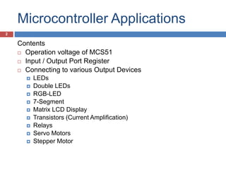
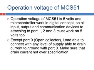
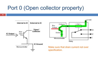
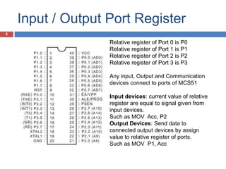
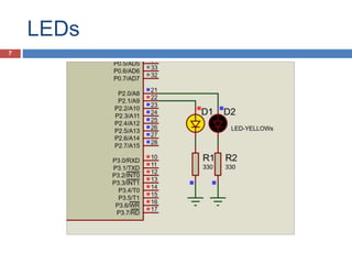
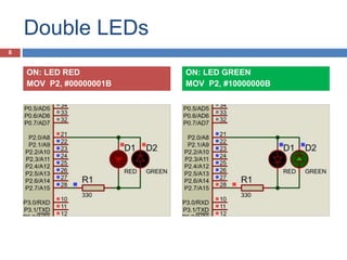
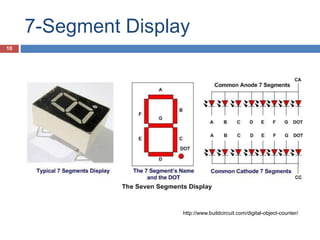
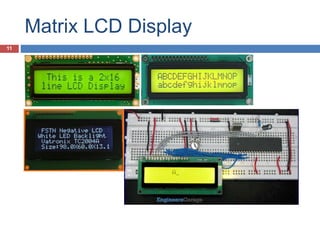
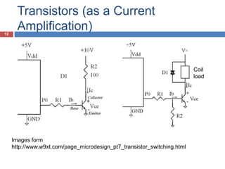
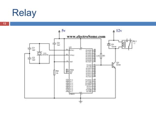
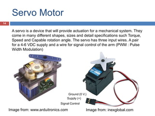
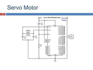
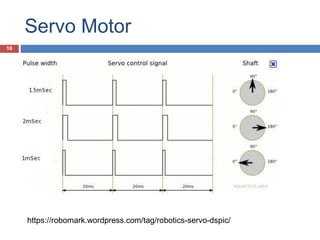
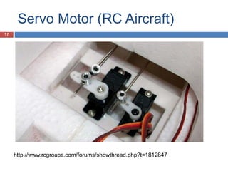
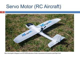
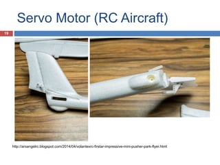
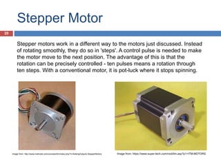
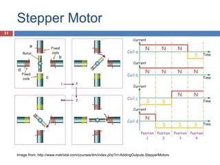
MICROCONTROLLER
MCS-51:
APPLICATIONS
Arkhom JODTANG
Civil Aviation Training Center
1
Microcontroller Applications
Contents
 Operation voltage of MCS51
 Input / Output Port Register
 Connecting to various Output Devices
 LEDs
 Double LEDs
 RGB-LED
 7-Segment
 Matrix LCD Display
 Transistors (Current Amplification)
 Relays
 Servo Motors
 Stepper Motor
2
Operation voltage of MCS51
 Operation voltage of MCS51 is 5 volts and
microcontroller work in digital concept, so all
input, output and communication devices to
attaching to port 1, 2 and 3 must work on 5
volts too.
 Except port 0 (Open collector), Load able to
connect with any level of supply able to drain
current to ground with port 0. Make sure that
drain current not over specification.
3
Port 0 (Open collector property)
Make sure that drain current not over
specification.
4
Microcontroller
Microcontroller
Relay
Input / Output Port Register
Relative register of Port 0 is P0
Relative register of Port 1 is P1
Relative register of Port 2 is P2
Relative register of Port 3 is P3
Any input, Output and Communication
devices connect to ports of MCS51
Input devices: current value of relative
register are equal to signal given from
input devices.
Such as MOV Acc, P2
Output Devices: Send data to
connected output devices by assign
value to relative register of ports.
Such as MOV P1, Acc
5
Output Devices6
LEDs
7
Double LEDs
ON: LED RED
MOV P2, #00000001B
ON: LED GREEN
MOV P2, #10000000B
8
RGB LEDs
Ground
P1.0
P1.1
P1.2
With PWM the LED is turned
on and off many times per
second. By adjusting duty
percentage, the brightness of
each color the LED can be
controlled.
Image from: en.wikipedia.org
Image from: www.protostack.com/blog/2011/06/atmega168a-pulse-width-modulation-pwm/
9
7-Segment Display
10
http://www.buildcircuit.com/digital-object-counter/
Matrix LCD Display
11
Transistors (as a Current
Amplification)
Images form
http://www.w9xt.com/page_microdesign_pt7_transistor_switching.html
Coil
load
12
Relay
13
Servo Motor
Image from: www.arduitronics.com Image from: inexglobal.com
A servo is a device that will provide actuation for a mechanical system. They
come in many different shapes, sizes and detail specifications such Torque,
Speed and Capable rotation angle. The servo has three input wires. A pair
for a 4-6 VDC supply and a wire for signal control of the arm (PWM : Pulse
Width Modulation)
Supply (+)
Ground (0 V.)
Signal Control
14
Servo Motor
15
Servo Motor
https://robomark.wordpress.com/tag/robotics-servo-dspic/
16
Servo Motor (RC Aircraft)
http://www.rcgroups.com/forums/showthread.php?t=1812847
17
Servo Motor (RC Aircraft)
http://arxangelrc.blogspot.com/2014/04/volantexrc-firstar-impressive-mini-pusher-park-flyer.html
18
Servo Motor (RC Aircraft)
http://arxangelrc.blogspot.com/2014/04/volantexrc-firstar-impressive-mini-pusher-park-flyer.html
19
Stepper Motor
Image from: http://www.matrixtsl.com/courses/itm/index.php?n=AddingOutputs.StepperMotors Image from: https://www.super-tech.com/root/itm.asp?p1=ITM-MOTORS
Stepper motors work in a different way to the motors just discussed. Instead
of rotating smoothly, they do so in 'steps'. A control pulse is needed to make
the motor move to the next position. The advantage of this is that the
rotation can be precisely controlled - ten pulses means a rotation through
ten steps. With a conventional motor, it is pot-luck where it stops spinning.
20
Stepper Motor
Image from: http://www.matrixtsl.com/courses/itm/index.php?n=AddingOutputs.StepperMotors
a
b
c
d
21
Such as
• Dual Motor Driver
Circuit Module22
Dual Motor Driver
THIS L293D DRIVER MODULE IS A MEDIUM POWER MOTOR DRIVER
PERFECT FOR DRIVING DC MOTORS AND STEPPER MOTORS. IT
USES THE POPULAR L293D MOTOR DRIVER IC. IT CAN DRIVE 4 DC
MOTORS IN ONE DIRECTION, OR DRIVE 2 DC MOTORS IN BOTH
THE DIRECTIONS.
23

Microprocessor Week 10: Applications

  • 1.
  • 2.
    Microcontroller Applications Contents  Operationvoltage of MCS51  Input / Output Port Register  Connecting to various Output Devices  LEDs  Double LEDs  RGB-LED  7-Segment  Matrix LCD Display  Transistors (Current Amplification)  Relays  Servo Motors  Stepper Motor 2
  • 3.
    Operation voltage ofMCS51  Operation voltage of MCS51 is 5 volts and microcontroller work in digital concept, so all input, output and communication devices to attaching to port 1, 2 and 3 must work on 5 volts too.  Except port 0 (Open collector), Load able to connect with any level of supply able to drain current to ground with port 0. Make sure that drain current not over specification. 3
  • 4.
    Port 0 (Opencollector property) Make sure that drain current not over specification. 4 Microcontroller Microcontroller Relay
  • 5.
    Input / OutputPort Register Relative register of Port 0 is P0 Relative register of Port 1 is P1 Relative register of Port 2 is P2 Relative register of Port 3 is P3 Any input, Output and Communication devices connect to ports of MCS51 Input devices: current value of relative register are equal to signal given from input devices. Such as MOV Acc, P2 Output Devices: Send data to connected output devices by assign value to relative register of ports. Such as MOV P1, Acc 5
  • 6.
  • 7.
  • 8.
    Double LEDs ON: LEDRED MOV P2, #00000001B ON: LED GREEN MOV P2, #10000000B 8
  • 9.
    RGB LEDs Ground P1.0 P1.1 P1.2 With PWMthe LED is turned on and off many times per second. By adjusting duty percentage, the brightness of each color the LED can be controlled. Image from: en.wikipedia.org Image from: www.protostack.com/blog/2011/06/atmega168a-pulse-width-modulation-pwm/ 9
  • 10.
  • 11.
  • 12.
    Transistors (as aCurrent Amplification) Images form http://www.w9xt.com/page_microdesign_pt7_transistor_switching.html Coil load 12
  • 13.
  • 14.
    Servo Motor Image from:www.arduitronics.com Image from: inexglobal.com A servo is a device that will provide actuation for a mechanical system. They come in many different shapes, sizes and detail specifications such Torque, Speed and Capable rotation angle. The servo has three input wires. A pair for a 4-6 VDC supply and a wire for signal control of the arm (PWM : Pulse Width Modulation) Supply (+) Ground (0 V.) Signal Control 14
  • 15.
  • 16.
  • 17.
    Servo Motor (RCAircraft) http://www.rcgroups.com/forums/showthread.php?t=1812847 17
  • 18.
    Servo Motor (RCAircraft) http://arxangelrc.blogspot.com/2014/04/volantexrc-firstar-impressive-mini-pusher-park-flyer.html 18
  • 19.
    Servo Motor (RCAircraft) http://arxangelrc.blogspot.com/2014/04/volantexrc-firstar-impressive-mini-pusher-park-flyer.html 19
  • 20.
    Stepper Motor Image from:http://www.matrixtsl.com/courses/itm/index.php?n=AddingOutputs.StepperMotors Image from: https://www.super-tech.com/root/itm.asp?p1=ITM-MOTORS Stepper motors work in a different way to the motors just discussed. Instead of rotating smoothly, they do so in 'steps'. A control pulse is needed to make the motor move to the next position. The advantage of this is that the rotation can be precisely controlled - ten pulses means a rotation through ten steps. With a conventional motor, it is pot-luck where it stops spinning. 20
  • 21.
    Stepper Motor Image from:http://www.matrixtsl.com/courses/itm/index.php?n=AddingOutputs.StepperMotors a b c d 21
  • 22.
    Such as • DualMotor Driver Circuit Module22
  • 23.
    Dual Motor Driver THISL293D DRIVER MODULE IS A MEDIUM POWER MOTOR DRIVER PERFECT FOR DRIVING DC MOTORS AND STEPPER MOTORS. IT USES THE POPULAR L293D MOTOR DRIVER IC. IT CAN DRIVE 4 DC MOTORS IN ONE DIRECTION, OR DRIVE 2 DC MOTORS IN BOTH THE DIRECTIONS. 23