Downloaded 783 times


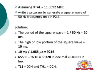


Here is the program to generate a 50 Hz square wave on P2.3: ``` MOV TMOD, #01H ; Timer 1, mode 1 MOV TH1, #DCH MOV TL1, #00H SETB TR1 ; Start timer 1 AGAIN: JNB TF1, AGAIN; Wait for overflow CPL P2.3 ; Toggle P2.3 CLR TF1 ; Clear overflow flag SJMP AGAIN ; Repeat ``` This program uses Timer 1 in mode 1 (16-bit auto-reload) with TH1=DC00h and TL1=00h to generate a 10 ms delay