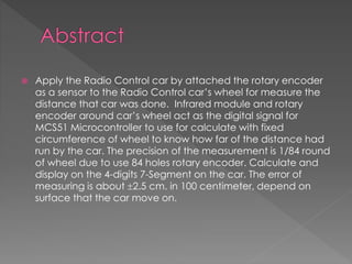
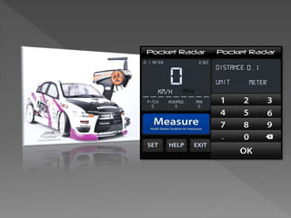
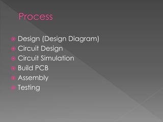
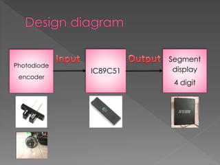
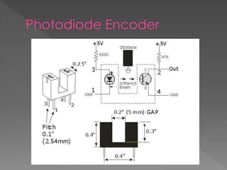
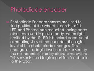
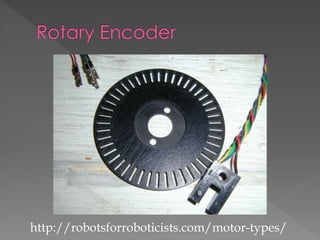
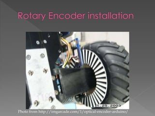
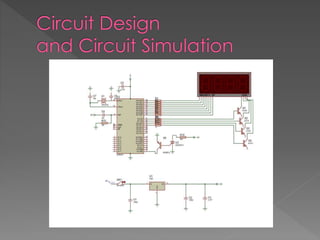
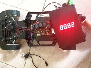
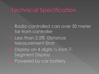
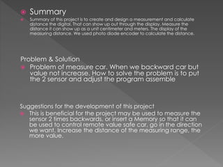
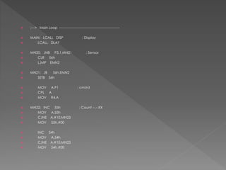
 Apply the Radio Control car by attached the rotary encoder
as a sensor to the Radio Control car’s wheel for measure the
distance that car was done. Infrared module and rotary
encoder around car’s wheel act as the digital signal for
MCS51 Microcontroller to use for calculate with fixed
circumference of wheel to know how far of the distance had
run by the car. The precision of the measurement is 1/84 round
of wheel due to use 84 holes rotary encoder. Calculate and
display on the 4-digits 7-Segment on the car. The error of
measuring is about 2.5 cm. in 100 centimeter, depend on
surface that the car move on.
 1. For study about measurement.
 2. For study about each electronics devices.
 3. For future generations to study.
 Design (Design Diagram)
 Circuit Design
 Circuit Simulation
 Build PCB
 Assembly
 Testing
Photodiode
encoder
IC89C51
Segment
display
4 digit
 Photodiode Encoder
 Rotary Encoder
 MCS51 Controller
 7-Segment LED Display
 Photodiode Encoder sensors are used to
find position of the wheel. It consists of IR
LED and Photodiode mounted facing each
other enclosed in plastic body. When light
emitted by the IR LED is blocked because of
alternating slots of the encoder disc logic
level of the photo diode changes. This
change in the logic level can be sensed by
the microcontroller or by discrete hardware.
This sensor is used to give position feedback
to the robot.
http://robotsforroboticists.com/motor-types/
Photo from http://imgarcade.com/1/optical-encoder-arduino/
 When distance measuring car
movement the photodiode encoder will
take input to IC then an IC will
processing by software (The firmware for
distance meter was written in c with IC
compiler). After that An IC will calculate,
memory and send to segment display.
1. Radio controlled cars over 50 meter
far from controller
2. Less than 2.5% Distance
Measurement Error
3. Display on 4 digits ½ inch 7-
Segment Display
4. Powered by car battery
 Summary
 Summary of this project is to create and design a measurement and calculate
distance the digital. That can show up out through the display. Measure the
distance it can show up as a unit centimeter and meters. The display of the
measuring distance. We used photo diode encoder to calculate the distance.
Problem & Solution
 Problem of measure car. When we backward car but
value not increase. How to solve the problem is to put
the 2 sensor and adjust the program assemble
Suggestions for the development of this project
 This is beneficial for the project may be used to measure the
sensor 2 times backwards, or insert a Memory so that it can
be used to control remote value safe car, go in the direction
we want. Increase the distance of the measuring range, the
more value.
 Assembly Code
 ORG 0000H
 LJMP INIT
 ORG 000BH
 LJMP TIME
 ORG 0030H
 INIT: MOV P0,#00
 MOV P2,#00
 MOV P1,#0FFH
 MOV P3,#0FFH
 MOV R0,#00 ; GP
 MOV R1,#00 ; GP
 MOV R2,#00 ;
 MOV R3,#00 ;
 MOV R4,#00 ;
 MOV R5,#00 ; Delay
 MOV R6,#00 ; Delay
 MOV R7,#00 ; Delay

 MOV 50h,#00
 MOV 51h,#00
 MOV 52h,#00
 MOV 53h,#00
 MOV 54h,#00
 MOV 55h,#00
 SETB 56h
 ;---> Main Loop -----------------------------------------------------
 MAIN: LCALL DISP ; Display
 LCALL DLAY
 MN20: JNB P3.1,MN21 ; Sensor
 CLR 56h
 LJMP EMN2
 MN21: JB 56h,EMN2
 SETB 56h
 MOV A,P1 ; cm/rd
 CPL A
 MOV R4,A
 MN22: INC 55h ; Count --.--XX
 MOV A,55h
 CJNE A,#10,MN23
 MOV 55h,#00
 INC 54h
 MOV A,54h
 CJNE A,#10,MN23
 MOV 54h,#00
 INC 53h ; Count
 MOV A,53h
 CJNE A,#10,MN23
 MOV 53h,#00
 INC 52h
 MOV A,52h
 CJNE A,#10,MN23
 MOV 52h,#00
 INC 51h
 MOV A,51h
 CJNE A,#10,MN23
 MOV 51h,#00
 INC 50h
 MOV A,50h
 CJNE A,#10,MN23
 MOV 50h,#00
 MN23: DJNZ R4,MN22
 EMN2: NOP
 LJMP MAIN
 ;---> Display -------------------------------------------------------
 DISP: SETB P2.0 ; Display
 SETB P2.1
 SETB P2.6
 SETB P2.7
 DS00: INC 60h
 MOV A,60h
 CJNE A,#04,DS10
 MOV 60h,#00
 MOV A,60h
 DS10: CJNE A,#00,DS20
 MOV DPTR,#TAB2
 MOV A,50h
 MOVC A,@A+DPTR
 MOV P0,A
 CLR P2.6
 LJMP EDSX
 DS20: CJNE A,#01,DS30
 MOV DPTR,#TAB1
 MOV A,51h
 MOVC A,@A+DPTR
 CLR ACC.4 ; Dot
 MOV P0,A
 CLR P2.1
 LJMP EDSX
 DS30: CJNE A,#02,DS40
 MOV DPTR,#TAB2
 MOV A,52h
 MOVC A,@A+DPTR
 MOV P0,A
 CLR P2.7
 LJMP EDSX
 DS40: CJNE A,#03,DS50
 MOV DPTR,#TAB1
 MOV A,53h
 MOVC A,@A+DPTR
 MOV P0,A
 CLR P2.0
 LJMP EDSX
 DS50: NOP
 EDSX: RET
 TAB1: DB 014H,0D7H,031H,091H,0D2H,098H,018H,0D5H,010H,090H
 DB 03BH
 ; EDC.BGAF
 TAB2: DB 088H,0BBH,0C2H,092H,0B1H,094H,084H,0BAH,080H,090H
 ; .CDEGBFA
 ;---> Timer 0 Interrupt ---------------------------------------------
 TIME: NOP
 ETIM: RETI
 DLAY: MOV R7,#00
 DJNZ R7,$
 RET
 HLAY: MOV R6,#00
 HL00: MOV R7,#00
 DJNZ R7,$
 LCALL DISP
 DJNZ R6,HL00
 RET
 HHLY: MOV R5,#06
 HH00: MOV R6,#00
 HH01: MOV R7,#00
 DJNZ R7,$
 DJNZ R6,HH01
 DJNZ R5,HH00
 RET
 END
Chairat Pipitagule 5411300040
Thanawin Surakit 5411300060
Krishnaphat Mingsamdang 5411300370
Prapoj Iemsanguan 5411301390
Panjapong Loysawai 5411301470
CM 50 Avionics division
Civil Aviation Training Center

Distance Measuring Car

  • 3.
     Apply theRadio Control car by attached the rotary encoder as a sensor to the Radio Control car’s wheel for measure the distance that car was done. Infrared module and rotary encoder around car’s wheel act as the digital signal for MCS51 Microcontroller to use for calculate with fixed circumference of wheel to know how far of the distance had run by the car. The precision of the measurement is 1/84 round of wheel due to use 84 holes rotary encoder. Calculate and display on the 4-digits 7-Segment on the car. The error of measuring is about 2.5 cm. in 100 centimeter, depend on surface that the car move on.
  • 5.
     1. Forstudy about measurement.  2. For study about each electronics devices.  3. For future generations to study.
  • 6.
     Design (DesignDiagram)  Circuit Design  Circuit Simulation  Build PCB  Assembly  Testing
  • 7.
  • 8.
     Photodiode Encoder Rotary Encoder  MCS51 Controller  7-Segment LED Display
  • 10.
     Photodiode Encodersensors are used to find position of the wheel. It consists of IR LED and Photodiode mounted facing each other enclosed in plastic body. When light emitted by the IR LED is blocked because of alternating slots of the encoder disc logic level of the photo diode changes. This change in the logic level can be sensed by the microcontroller or by discrete hardware. This sensor is used to give position feedback to the robot.
  • 11.
  • 12.
  • 14.
     When distancemeasuring car movement the photodiode encoder will take input to IC then an IC will processing by software (The firmware for distance meter was written in c with IC compiler). After that An IC will calculate, memory and send to segment display.
  • 18.
    1. Radio controlledcars over 50 meter far from controller 2. Less than 2.5% Distance Measurement Error 3. Display on 4 digits ½ inch 7- Segment Display 4. Powered by car battery
  • 19.
     Summary  Summaryof this project is to create and design a measurement and calculate distance the digital. That can show up out through the display. Measure the distance it can show up as a unit centimeter and meters. The display of the measuring distance. We used photo diode encoder to calculate the distance. Problem & Solution  Problem of measure car. When we backward car but value not increase. How to solve the problem is to put the 2 sensor and adjust the program assemble Suggestions for the development of this project  This is beneficial for the project may be used to measure the sensor 2 times backwards, or insert a Memory so that it can be used to control remote value safe car, go in the direction we want. Increase the distance of the measuring range, the more value.
  • 20.
     Assembly Code ORG 0000H  LJMP INIT  ORG 000BH  LJMP TIME  ORG 0030H  INIT: MOV P0,#00  MOV P2,#00  MOV P1,#0FFH  MOV P3,#0FFH  MOV R0,#00 ; GP  MOV R1,#00 ; GP  MOV R2,#00 ;  MOV R3,#00 ;  MOV R4,#00 ;  MOV R5,#00 ; Delay  MOV R6,#00 ; Delay  MOV R7,#00 ; Delay   MOV 50h,#00  MOV 51h,#00  MOV 52h,#00  MOV 53h,#00  MOV 54h,#00  MOV 55h,#00  SETB 56h
  • 21.
     ;---> MainLoop -----------------------------------------------------  MAIN: LCALL DISP ; Display  LCALL DLAY  MN20: JNB P3.1,MN21 ; Sensor  CLR 56h  LJMP EMN2  MN21: JB 56h,EMN2  SETB 56h  MOV A,P1 ; cm/rd  CPL A  MOV R4,A  MN22: INC 55h ; Count --.--XX  MOV A,55h  CJNE A,#10,MN23  MOV 55h,#00  INC 54h  MOV A,54h  CJNE A,#10,MN23  MOV 54h,#00
  • 22.
     INC 53h; Count  MOV A,53h  CJNE A,#10,MN23  MOV 53h,#00  INC 52h  MOV A,52h  CJNE A,#10,MN23  MOV 52h,#00  INC 51h  MOV A,51h  CJNE A,#10,MN23  MOV 51h,#00  INC 50h  MOV A,50h  CJNE A,#10,MN23  MOV 50h,#00  MN23: DJNZ R4,MN22  EMN2: NOP  LJMP MAIN
  • 23.
     ;---> Display-------------------------------------------------------  DISP: SETB P2.0 ; Display  SETB P2.1  SETB P2.6  SETB P2.7  DS00: INC 60h  MOV A,60h  CJNE A,#04,DS10  MOV 60h,#00  MOV A,60h  DS10: CJNE A,#00,DS20  MOV DPTR,#TAB2  MOV A,50h  MOVC A,@A+DPTR  MOV P0,A  CLR P2.6  LJMP EDSX
  • 24.
     DS20: CJNEA,#01,DS30  MOV DPTR,#TAB1  MOV A,51h  MOVC A,@A+DPTR  CLR ACC.4 ; Dot  MOV P0,A  CLR P2.1  LJMP EDSX  DS30: CJNE A,#02,DS40  MOV DPTR,#TAB2  MOV A,52h  MOVC A,@A+DPTR  MOV P0,A  CLR P2.7  LJMP EDSX  DS40: CJNE A,#03,DS50  MOV DPTR,#TAB1  MOV A,53h  MOVC A,@A+DPTR  MOV P0,A  CLR P2.0  LJMP EDSX  DS50: NOP  EDSX: RET  TAB1: DB 014H,0D7H,031H,091H,0D2H,098H,018H,0D5H,010H,090H  DB 03BH  ; EDC.BGAF  TAB2: DB 088H,0BBH,0C2H,092H,0B1H,094H,084H,0BAH,080H,090H  ; .CDEGBFA
  • 25.
     ;---> Timer0 Interrupt ---------------------------------------------  TIME: NOP  ETIM: RETI  DLAY: MOV R7,#00  DJNZ R7,$  RET  HLAY: MOV R6,#00  HL00: MOV R7,#00  DJNZ R7,$  LCALL DISP  DJNZ R6,HL00  RET  HHLY: MOV R5,#06  HH00: MOV R6,#00  HH01: MOV R7,#00  DJNZ R7,$  DJNZ R6,HH01  DJNZ R5,HH00  RET  END
  • 26.
    Chairat Pipitagule 5411300040 ThanawinSurakit 5411300060 Krishnaphat Mingsamdang 5411300370 Prapoj Iemsanguan 5411301390 Panjapong Loysawai 5411301470 CM 50 Avionics division Civil Aviation Training Center