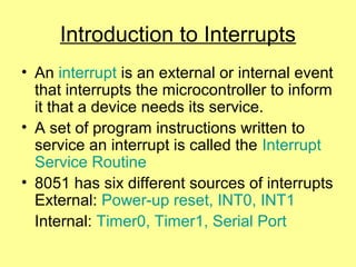
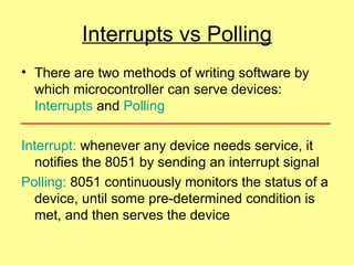
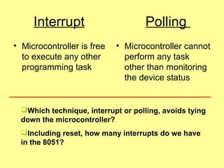
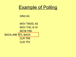
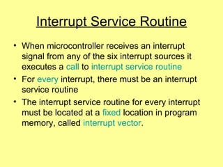
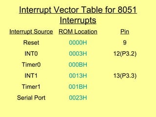
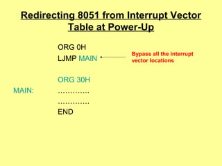
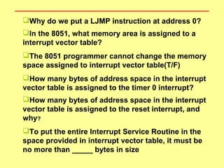
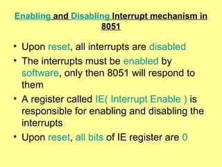
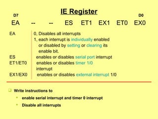
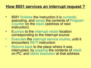
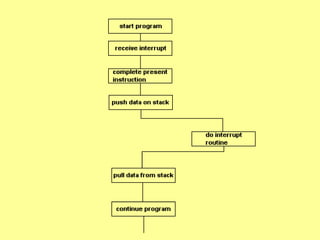
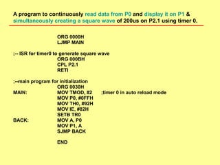
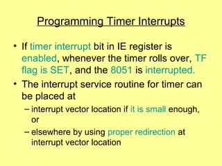
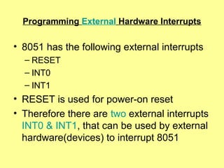
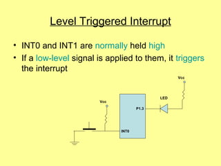
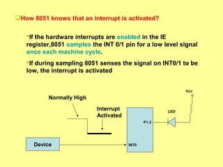
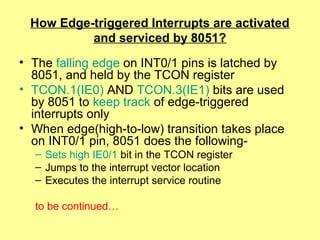
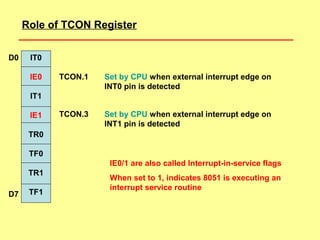
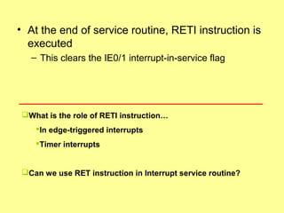
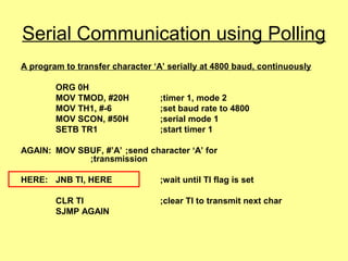
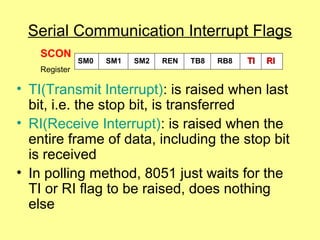
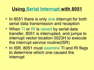
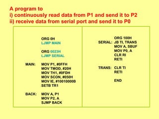
this ppt is related to the intrupts related to the 8051 microcontroller ..
topics are introduction to intrupts
intrerrupts vs pollings
difference between intrupts snd pollings
2. Introduction to Interrupts
• An interrupt is an external or internal event
that interrupts the microcontroller to inform
it that a device needs its service.
• A set of program instructions written to
service an interrupt is called the Interrupt
Service Routine
• 8051 has six different sources of interrupts
External: Power-up reset, INT0, INT1
Internal: Timer0, Timer1, Serial Port
3. Interrupts vs Polling
• There are two methods of writing software by
which microcontroller can serve devices:
Interrupts and Polling
Interrupt: whenever any device needs service, it
notifies the 8051 by sending an interrupt signal
Polling: 8051 continuously monitors the status of a
device, until some pre-determined condition is
met, and then serves the device
4. Interrupt Polling
• Microcontroller is free
to execute any other
programming task
• Microcontroller cannot
perform any task
other than monitoring
the device status
Which technique, interrupt or polling, avoids tying
down the microcontroller?
Including reset, how many interrupts do we have
in the 8051?
5. Example of Polling
ORG 0H
MOV TMOD, #2
MOV TH0, #-10
SETB TR0
BACK:JNB TF0, BACK
CLR TR0
CLR TF0
6. Interrupt Service Routine
• When microcontroller receives an interrupt
signal from any of the six interrupt sources it
executes a call to interrupt service routine
• For every interrupt, there must be an interrupt
service routine
• The interrupt service routine for every interrupt
must be located at a fixed location in program
memory, called interrupt vector.
7. Interrupt Vector Table for 8051
Interrupts
Interrupt Source ROM Location Pin
Reset 0000H 9
INT0 0003H 12(P3.2)
Timer0 000BH
INT1 0013H 13(P3.3)
Timer1 001BH
Serial Port 0023H
8. Redirecting 8051 from Interrupt Vector
Table at Power-Up
ORG 0H
LJMP MAIN
ORG 30H
MAIN: ………….
………….
END
Bypass all the interrupt
vector locations
9. Why do we put a LJMP instruction at address 0?
In the 8051, what memory area is assigned to a
interrupt vector table?
The 8051 programmer cannot change the memory
space assigned to interrupt vector table(T/F)
How many bytes of address space in the interrupt
vector table is assigned to the timer 0 interrupt?
How many bytes of address space in the interrupt
vector table is assigned to the reset interrupt, and
why?
To put the entire Interrupt Service Routine in the
space provided in interrupt vector table, it must be
no more than _____ bytes in size
10. Enabling and Disabling Interrupt mechanism in
8051
• Upon reset, all interrupts are disabled
• The interrupts must be enabled by
software, only then 8051 will respond to
them
• A register called IE( Interrupt Enable ) is
responsible for enabling and disabling the
interrupts
• Upon reset, all bits of IE register are 0
11. IE Register
EA 0, Disables all interrupts
1, each interrupt is individually enabled
or disabled by setting or clearing its
enable bit.
ES enables or disables serial port interrupt
ET1/ET0 enables or disables timer 1/0
interrupt
EX1/EX0 enables or disables external interrupt 1/0
EA -- -- ES ET1 EX1 ET0 EX0
D0D7
Write instructions to
enable serial interrupt and timer 0 interrupt
Disable all interrupts
12. How 8051 services an interrupt request ?
• 8051 finishes the instruction it is currently
executing, and saves the contents of Program
Counter on the stack (address of next
instruction)
• It jumps to the interrupt vector location
corresponding to the interrupt source
• Executes the interrupt service routine, until it
encounters RETI instruction
• Returns back to the place where it was
interrupted, by popping the contents of stack
on PC, and starts execution at that address
13.
14. ORG 0000H
LJMP MAIN
;-- ISR for timer0 to generate square wave
ORG 000BH
CPL P2.1
RETI
;--main program for initialization
ORG 0030H
MAIN: MOV TMOD, #2 ;timer 0 in auto reload mode
MOV P0, #0FFH
MOV TH0, #92H
MOV IE, #82H
SETB TR0
BACK: MOV A, P0
MOV P1, A
SJMP BACK
END
A program to continuously read data from P0 and display it on P1 &
simultaneously creating a square wave of 200us on P2.1 using timer 0.
15. Programming Timer Interrupts
• If timer interrupt bit in IE register is
enabled, whenever the timer rolls over, TF
flag is SET, and the 8051 is interrupted.
• The interrupt service routine for timer can
be placed at
– interrupt vector location if it is small enough,
or
– elsewhere by using proper redirection at
interrupt vector location
16. Programming External Hardware Interrupts
• 8051 has the following external interrupts
– RESET
– INT0
– INT1
• RESET is used for power-on reset
• Therefore there are two external interrupts
INT0 & INT1, that can be used by external
hardware(devices) to interrupt 8051
17. How interrupts are activated?
• There are two activation levels for the
external hardware interrupts
– Level triggered
– Edge triggered
• Level triggered interrupts is the default
mode upon RESET of the 8051
18. Level Triggered Interrupt
• INT0 and INT1 are normally held high
• If a low-level signal is applied to them, it triggers
the interrupt
Vcc
P1.3
Vcc
INT0
LED
19. P1.3
Vcc
INT0
LED
Device
Normally High
Interrupt
Activated
How 8051 knows that an interrupt is activated?
If the hardware interrupts are enabled in the IE
register,8051 samples the INT 0/1 pin for a low level signal
once each machine cycle.
If during sampling 8051 senses the signal on INT0/1 to be
low, the interrupt is activated
20. What is the minimum duration for which INT
0/1 pin must be held low for interrupt to be
activated?
The pin must be held low until the start of the
execution of Interrupt Service Routine
The minimum duration is 4 machine cycles.
How can we make sure that a single interrupt
is not interpreted as multiple interrupts?
The low-level on INT0/1 pin be brought back to high before
the execution of RETI instruction in Interrupt Service
Routine
21. Remember that…..
• There are two activation levels for the
external hardware interrupts
– Level triggered
– Edge triggered
• Level triggered interrupts is the default
mode upon RESET of the 8051
22. Edge Triggered Interrupts
• We must program the bits of TCON register to make
interrupts edge-triggered
• When a high-to-low signal is applied to INT0/1 pin, the
8051 will be interrupted
P1.3
Vcc
INT0
LED
Device
High-to-low
transition
23. IT0
IE0
IT1
IE1
TR0
TF0
TR1
TF1
D0
D7
TCON.0
TCON.2
0, INT0 becomes level-triggered interrupt
1, INT0 becomes edge-triggered interrupt
0, INT1 becomes level-triggered interrupt
1, INT1 becomes edge-triggered interrupt
To make INT0 edge-triggered the instruction
is SETB TCON.0
To make INT1 edge-triggered the instruction
is SETB TCON.2
Role of TCON Register
24. How Edge-triggered Interrupts are activated
and serviced by 8051?
• The falling edge on INT0/1 pins is latched by
8051, and held by the TCON register
• TCON.1(IE0) AND TCON.3(IE1) bits are used
by 8051 to keep track of edge-triggered
interrupts only
• When edge(high-to-low) transition takes place
on INT0/1 pin, 8051 does the following-
– Sets high IE0/1 bit in the TCON register
– Jumps to the interrupt vector location
– Executes the interrupt service routine
to be continued…
25. IT0
IE0
IT1
IE1
TR0
TF0
TR1
TF1
D0
D7
TCON.1
TCON.3
Set by CPU when external interrupt edge on
INT0 pin is detected
Role of TCON Register
Set by CPU when external interrupt edge on
INT1 pin is detected
IE0/1 are also called Interrupt-in-service flags
When set to 1, indicates 8051 is executing an
interrupt service routine
26. • At the end of service routine, RETI instruction is
executed
– This clears the IE0/1 interrupt-in-service flag
What is the role of RETI instruction…
In edge-triggered interrupts
Timer interrupts
Can we use RET instruction in Interrupt service routine?
28. Serial Communication using Polling
A program to transfer character ‘A’ serially at 4800 baud, continuously
ORG 0H
MOV TMOD, #20H ;timer 1, mode 2
MOV TH1, #-6 ;set baud rate to 4800
MOV SCON, #50H ;serial mode 1
SETB TR1 ;start timer 1
AGAIN: MOV SBUF, #’A’ ;send character ‘A’ for
;transmission
HERE: JNB TI, HERE ;wait until TI flag is set
CLR TI ;clear TI to transmit next char
SJMP AGAIN
29. Serial Communication Interrupt Flags
• TI(Transmit Interrupt): is raised when last
bit, i.e. the stop bit, is transferred
• RI(Receive Interrupt): is raised when the
entire frame of data, including the stop bit
is received
• In polling method, 8051 just waits for the
TI or RI flag to be raised, does nothing
else
SM0 SM1 SM2 REN TB8 RB8 TI RITI RI
SCON
Register
30. Using Serial Interrupt with 8051
• In 8051 there is only one interrupt for both
serial data transmission and reception
• When TI or RI is raised by serial data
transfer, 8051 is interrupted, and jumps to
interrupt vector location 0023H to execute
the interrupt service routine(ISR)
• In ISR, 8051 must examine TI and RI flags
to determine which one caused the
interrupt
31. A program to
i) continuously read data from P1 and send it to P2
ii) receive data from serial port and send it to P0
ORG 0H
LJMP MAIN
ORG 0023H
LJMP SERIAL
MAIN: MOV P1, #0FFH
MOV TMOD, #20H
MOV TH1, #0FDH
MOV SCON, #050H
MOV IE, #10010000B
SETB TR1
BACK: MOV A, P1
MOV P2, A
SJMP BACK
ORG 100H
SERIAL: JB TI, TRANS
MOV A, SBUF
MOV P0, A
CLR RI
RETI
TRANS: CLR TI
RETI
END
32. Interrupt Priority in 8051
What happens if two interrupts are
activated at the same time?
Which of these two interrupts is serviced
first?
– The interrupt which has the highest priority is
serviced first
– By default, 8051 assigns a priority level to all
interrupts upon RESET
33. 8051 Interrupt Priority upon RESET
Highest to Lowest Priority
External Interrupt 0 INT0
Timer Interrupt 0 TF0
External Interrupt 1 INT1
Timer Interrupt 1 TF1
Serial Communication RI + TI
34. • They are latched and kept internally by 8051
• Then 8051 polls all interrupts according to the
default priority levels
• If any interrupt is activated, it is serviced in that
sequence.
• Therefore IE0(INT0) is serviced first, then
TF0(timer0), and finally IE1(INT1)
What happens if interrupts INT0, TF0, INT1 are
activated at the same time? Assume default priority
levels and edge-triggered external interrupts.
35. Interrupt Priority Register
PS Serial Port Priority bit
PT1 Timer1 interrupt priority bit
PX1 External interrupt 1 priority bit
PT0 Timer0 interrupt priority bit
PX0 External interrupt 0 priority bit
-- -- PT2 PS PT1 PX1 PT0 PX0PX0
IP
Register
D0D7
Priority bit = 1, assigns high priority
0, assigns low priority
36. Assume that after RESET, the Interrupt priority
is set by the instruction
MOV IP, 00001100B
Discuss the sequence in which the interrupts are
serviced.
What happens if the 8051 is executing the ISR
of an interrupt and another higher priority
interrupt is activated?
Upon RESET all interrupts have the same
priority.(T/F)