The document details the programming and functionalities of timers and counters in the 8051 microcontroller, covering their register configurations, modes of operation, and example code for various timing applications. It emphasizes timer control registers and how to set up timers for generating delays or counting events through specific pin inputs. Additionally, it provides insights into calculating timer values for desired delays and demonstrates practical applications with sample C code.


![Program
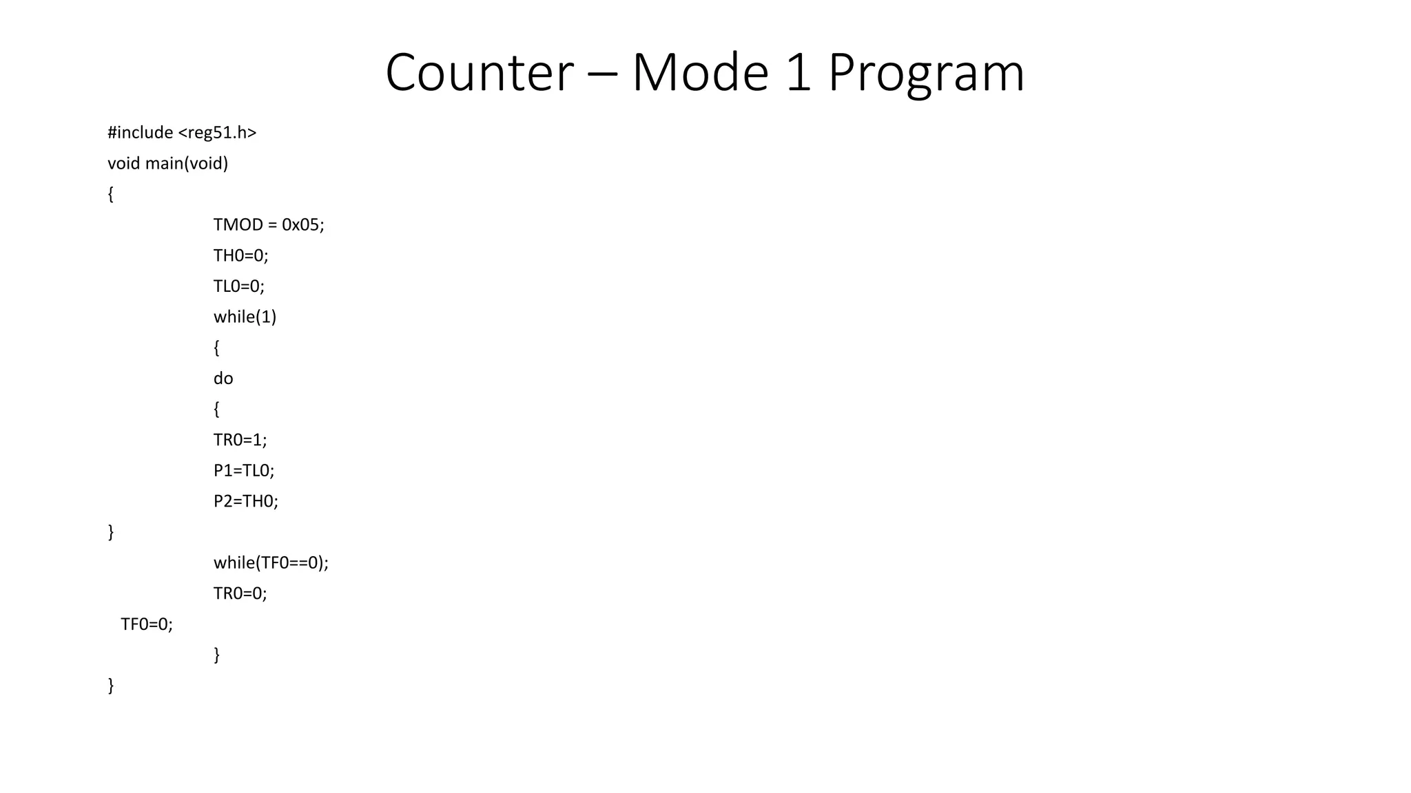
#include <reg51.h>
sbit MYSW=P2^0; //input switch
void main(void){
unsigned char z;
unsigned char Mess1[]=“Normal Speed”;
unsigned char Mess2[]=“High Speed”;
TMOD=0x20; //use Timer 1, mode 2
TH1=0xFF; //28800 for normal
SCON=0x50;
TR1=1; //start timer
if(MYSW==0) {
for (z=0;z<12;z++) {
SBUF=Mess1[z]; //place value in buffer
while(TI==0); //wait for transmit
TI=0;
}
}](https://image.slidesharecdn.com/6-interruptsprogramming-27-03-2024-240422120833-6fa27b2f/75/6-Interrupts-Programming-27-03-2024-pptx-60-2048.jpg)
![Program
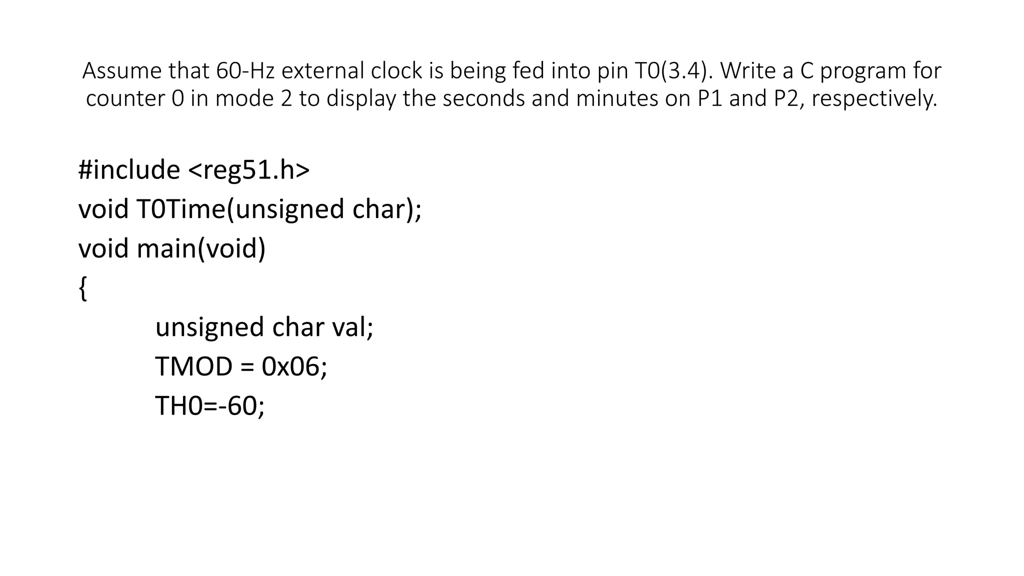
else
{
PCON=PCON|0x80; //for high speed of 56K
for (z=0;z<10;z++) {
SBUF=Mess2[z]; //place value in buffer
while(TI==0); //wait for transmit
TI=0;
}
}
}](https://image.slidesharecdn.com/6-interruptsprogramming-27-03-2024-240422120833-6fa27b2f/75/6-Interrupts-Programming-27-03-2024-pptx-61-2048.jpg)