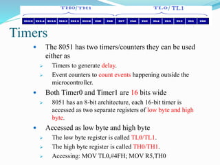
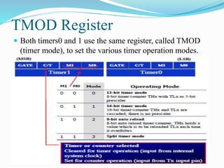
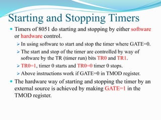
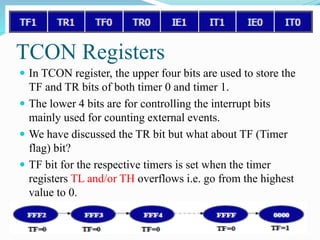
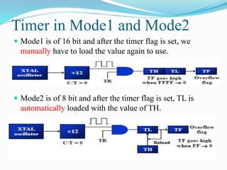
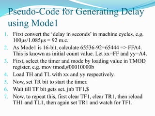
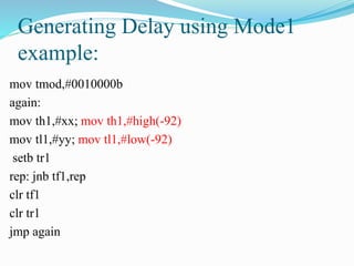
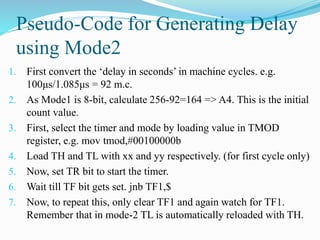
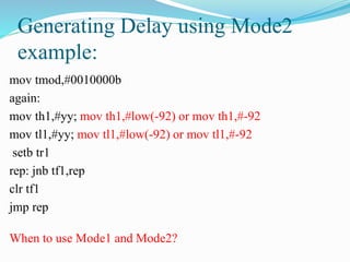
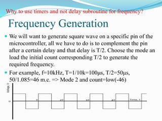
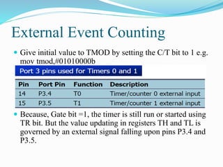
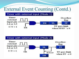
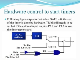
GENERATING SQUARE WAVES USING 8051 TIMES
Objectives of the Lab
 Learning about 8051 timers
 Registers governing timers
 Generating delays or certain frequencies using timers
Deciding Pins or Ports to use
Use with
caution
If EA high
*We only
need one pin
to generate sq
wave
Timers
 The 8051 has two timers/counters they can be used
either as
 Timers to generate delay.
 Event counters to count events happening outside the
microcontroller.
 Both Timer0 and Timer1 are 16 bits wide
 8051 has an 8-bit architecture, each 16-bit timer is
accessed as two separate registers of low byte and high
byte.
 Accessed as low byte and high byte
 The low byte register is called TL0/TL1.
 The high byte register is called TH0/TH1.
 Accessing: MOV TL0,#4FH; MOV R5,TH0
/ /
TMOD Register
 Both timers0 and 1 use the same register, called TMOD
(timer mode), to set the various timer operation modes.
Starting and Stopping Timers
 Timers of 8051 do starting and stopping by either software
or hardware control.
 In using software to start and stop the timer where GATE=0.
 The start and stop of the timer are controlled by way of
software by the TR (timer run) bits TR0 and TR1.
 TR0=1, timer 0 starts and TR0=0 timer 0 stops.
 Above instructions work if GATE=0 in TMOD register.
 The hardware way of starting and stopping the timer by an
external source is achieved by making GATE=1 in the
TMOD register.
TCON Registers
 In TCON register, the upper four bits are used to store the
TF and TR bits of both timer 0 and timer 1.
 The lower 4 bits are for controlling the interrupt bits
mainly used for counting external events.
 We have discussed the TR bit but what about TF (Timer
flag) bit?
 TF bit for the respective timers is set when the timer
registers TL and/or TH overflows i.e. go from the highest
value to 0.
Timer in Mode1 and Mode2
 Mode1 is of 16 bit and after the timer flag is set, we
manually have to load the value again to use.
 Mode2 is of 8 bit and after the timer flag is set, TL is
automatically loaded with the value of TH.
Pseudo-Code for Generating Delay
using Mode1
1. First convert the ‘delay in seconds’ in machine cycles. e.g.
100μs/1.085μs = 92 m.c.
2. As Mode1 is 16-bit, calculate 65536-92=65444 => FFA4.
This is known as initial count value. Let xx=FF and yy=A4.
3. First, select the timer and mode by loading value in TMOD
register, e.g. mov tmod,#00010000b
4. Load TH and TL with xx and yy respectively.
5. Now, set TR bit to start the timer.
6. Wait till TF bit gets set. jnb TF1,$
7. Now, to repeat this, first clear TF1, clear TR1, then reload
TH1 and TL1, then again set TR1 and watch for TF1.
Generating Delay using Mode1
example:
mov tmod,#0010000b
again:
mov th1,#xx; mov th1,#high(-92)
mov tl1,#yy; mov tl1,#low(-92)
setb tr1
rep: jnb tf1,rep
clr tf1
clr tr1
jmp again
Pseudo-Code for Generating Delay
using Mode2
1. First convert the ‘delay in seconds’ in machine cycles. e.g.
100μs/1.085μs = 92 m.c.
2. As Mode1 is 8-bit, calculate 256-92=164 => A4. This is the initial
count value.
3. First, select the timer and mode by loading value in TMOD
register, e.g. mov tmod,#00100000b
4. Load TH and TL with xx and yy respectively. (for first cycle only)
5. Now, set TR bit to start the timer.
6. Wait till TF bit gets set. jnb TF1,$
7. Now, to repeat this, only clear TF1 and again watch for TF1.
Remember that in mode-2 TL is automatically reloaded with TH.
Generating Delay using Mode2
example:
mov tmod,#0010000b
again:
mov th1,#yy; mov th1,#low(-92) or mov th1,#-92
mov tl1,#yy; mov tl1,#low(-92) or mov tl1,#-92
setb tr1
rep: jnb tf1,rep
clr tf1
jmp rep
When to use Mode1 and Mode2?
Frequency Generation
 We will want to generate square wave on a specific pin of the
microcontroller, all we have to do is to complement the pin
after a certain delay and that delay is T/2. Choose the mode an
load the initial count corresponding T/2 to generate the
required frequency.
 For example, f=10kHz, T=1/10k=100μs, T/2=50μs,
50/1.085=46 m.c. => Mode 2 and count=low(-46)
Why to use timers and not delay subroutine for frequency?
PWM Generation
 This is a square wave with fixed frequency but variable high
and low time.
 We have to make two different delays for when the pin is high
and the pin is low.
External Event Counting
 Give initial value to TMOD by setting the C/T bit to 1 e.g.
mov tmod,#01010000b
 Because, Gate bit =1, the timer is still run or started using
TR bit. But the value updating in registers TH and TL is
governed by an external signal falling upon pins P3.4 and
P3.5.
External Event Counting (Contd.)
Hardware control to start timers
 Following figure explains that when GATE = 0, the start
of the timer is done by hardware. TR bit still needs to be
set but if the external input on pins P3.2 and P3.3 is low,
the timer never starts.
Proteus Devices needed in this Lab
1. AT89c51
2. Oscilloscope
Lab Tasks
 Generate frequency of Workstation number in kHz.
 Quiz Next Week of LCD.
 Last Week Schedule: Project Checking, Vivas from
Project and Lab, Lab Manual Submission (in lab
experiment groups)

Micro c lab7(timers)

  • 1.
    GENERATING SQUARE WAVESUSING 8051 TIMES
  • 2.
    Objectives of theLab  Learning about 8051 timers  Registers governing timers  Generating delays or certain frequencies using timers
  • 3.
    Deciding Pins orPorts to use Use with caution If EA high *We only need one pin to generate sq wave
  • 4.
    Timers  The 8051has two timers/counters they can be used either as  Timers to generate delay.  Event counters to count events happening outside the microcontroller.  Both Timer0 and Timer1 are 16 bits wide  8051 has an 8-bit architecture, each 16-bit timer is accessed as two separate registers of low byte and high byte.  Accessed as low byte and high byte  The low byte register is called TL0/TL1.  The high byte register is called TH0/TH1.  Accessing: MOV TL0,#4FH; MOV R5,TH0 / /
  • 5.
    TMOD Register  Bothtimers0 and 1 use the same register, called TMOD (timer mode), to set the various timer operation modes.
  • 6.
    Starting and StoppingTimers  Timers of 8051 do starting and stopping by either software or hardware control.  In using software to start and stop the timer where GATE=0.  The start and stop of the timer are controlled by way of software by the TR (timer run) bits TR0 and TR1.  TR0=1, timer 0 starts and TR0=0 timer 0 stops.  Above instructions work if GATE=0 in TMOD register.  The hardware way of starting and stopping the timer by an external source is achieved by making GATE=1 in the TMOD register.
  • 7.
    TCON Registers  InTCON register, the upper four bits are used to store the TF and TR bits of both timer 0 and timer 1.  The lower 4 bits are for controlling the interrupt bits mainly used for counting external events.  We have discussed the TR bit but what about TF (Timer flag) bit?  TF bit for the respective timers is set when the timer registers TL and/or TH overflows i.e. go from the highest value to 0.
  • 8.
    Timer in Mode1and Mode2  Mode1 is of 16 bit and after the timer flag is set, we manually have to load the value again to use.  Mode2 is of 8 bit and after the timer flag is set, TL is automatically loaded with the value of TH.
  • 9.
    Pseudo-Code for GeneratingDelay using Mode1 1. First convert the ‘delay in seconds’ in machine cycles. e.g. 100μs/1.085μs = 92 m.c. 2. As Mode1 is 16-bit, calculate 65536-92=65444 => FFA4. This is known as initial count value. Let xx=FF and yy=A4. 3. First, select the timer and mode by loading value in TMOD register, e.g. mov tmod,#00010000b 4. Load TH and TL with xx and yy respectively. 5. Now, set TR bit to start the timer. 6. Wait till TF bit gets set. jnb TF1,$ 7. Now, to repeat this, first clear TF1, clear TR1, then reload TH1 and TL1, then again set TR1 and watch for TF1.
  • 10.
    Generating Delay usingMode1 example: mov tmod,#0010000b again: mov th1,#xx; mov th1,#high(-92) mov tl1,#yy; mov tl1,#low(-92) setb tr1 rep: jnb tf1,rep clr tf1 clr tr1 jmp again
  • 11.
    Pseudo-Code for GeneratingDelay using Mode2 1. First convert the ‘delay in seconds’ in machine cycles. e.g. 100μs/1.085μs = 92 m.c. 2. As Mode1 is 8-bit, calculate 256-92=164 => A4. This is the initial count value. 3. First, select the timer and mode by loading value in TMOD register, e.g. mov tmod,#00100000b 4. Load TH and TL with xx and yy respectively. (for first cycle only) 5. Now, set TR bit to start the timer. 6. Wait till TF bit gets set. jnb TF1,$ 7. Now, to repeat this, only clear TF1 and again watch for TF1. Remember that in mode-2 TL is automatically reloaded with TH.
  • 12.
    Generating Delay usingMode2 example: mov tmod,#0010000b again: mov th1,#yy; mov th1,#low(-92) or mov th1,#-92 mov tl1,#yy; mov tl1,#low(-92) or mov tl1,#-92 setb tr1 rep: jnb tf1,rep clr tf1 jmp rep When to use Mode1 and Mode2?
  • 13.
    Frequency Generation  Wewill want to generate square wave on a specific pin of the microcontroller, all we have to do is to complement the pin after a certain delay and that delay is T/2. Choose the mode an load the initial count corresponding T/2 to generate the required frequency.  For example, f=10kHz, T=1/10k=100μs, T/2=50μs, 50/1.085=46 m.c. => Mode 2 and count=low(-46) Why to use timers and not delay subroutine for frequency?
  • 14.
    PWM Generation  Thisis a square wave with fixed frequency but variable high and low time.  We have to make two different delays for when the pin is high and the pin is low.
  • 15.
    External Event Counting Give initial value to TMOD by setting the C/T bit to 1 e.g. mov tmod,#01010000b  Because, Gate bit =1, the timer is still run or started using TR bit. But the value updating in registers TH and TL is governed by an external signal falling upon pins P3.4 and P3.5.
  • 16.
  • 17.
    Hardware control tostart timers  Following figure explains that when GATE = 0, the start of the timer is done by hardware. TR bit still needs to be set but if the external input on pins P3.2 and P3.3 is low, the timer never starts.
  • 18.
    Proteus Devices neededin this Lab 1. AT89c51 2. Oscilloscope
  • 19.
    Lab Tasks  Generatefrequency of Workstation number in kHz.  Quiz Next Week of LCD.  Last Week Schedule: Project Checking, Vivas from Project and Lab, Lab Manual Submission (in lab experiment groups)